Open Device Partnership documentation guide
The purpose of this document is to guide you through an understanding of ODP regardless of where you are starting from or where your interest may lie.
The overall ODP umbrella is quite large and encompassing, and can be tricky to navigate through, so we will try to simplify that journey a little as well as giving direction on which path along the journey might best fit your interest or involvmement.
This document will briefly review the value proposition of ODP and why it is the right technology for the future of firmware development, at the right time.
Then the different 'tracks' of ODP will be explained. Here, you may find you are interested in only one of these tracks, or you may find you want to learn more about all of them.
Then, what is inside ODP and where to find it is detailed further - this is a good resource for those simply wishing to navigate the maze of contributed repositories that are available and which ones fit together for a given task.
Finally, for developers wishing to know more about how all of this comes together, a series of example implementation exercises are detailed. These can be explored in themselves or toward the end of the example's goal to create a complete virtual laptop that integrates the product of each of the individual exercises into a practical working end result.
You are in control of how you navigate through this guide, whether you proceed through it all one step at a time, or jump into the paths you find most compelling to your interest is entirely up to you.
Why ODP?
Modern computing devices are ubiquitous in our lives. They are integral to multiple aspects of our lives, from our workplace, to our finances, our creative endeavors, and our personal lifestyles.
Computer technology seemingly lept from its cradle a half century ago and never slowed its pace. It is easy to take much of it for granted.
We marvel as the new applications show us increasingly amazing opportunities. We also recognize and guard against the threats these applications pose to ourselves and society.
And in this heady environment, it is sometimes easy to forget that the "hidden parts" of these computers we use -- the lower-level hardware and firmware -- is often built upon languages and processes that, although having evolved to meet the demands of the time, are reaching the end of their practical sustainability for keeping up with the accelerating pace of the world around us.
What was originally just a "boot layer" and a few K of code for key hardware interfacing is now shouldering the responsibility of securing personal information and behavior patterns that a malicious intruder could use for nefarious purposes.
High-value proprietary algorithms and Artificial Intelligence models are now built into the firmware and must be locked down. An increasing number of "always ready" peripherals, such as the battery and charger, biometric identification mechanisms, network connections, and other concerns are being increasingly handled by independent MCUs that must coordinate with one another and with the host system in a responsive, increasingly complex, yet highly secure manner.
Trying to manage all of this with what has been the status-quo for these concerns in past decades, without memory-safe languages and with a loosely-federated collection of standards and patterns agreed upon by an ad-hoc consortium of vendors is increasingly dangerous and costly.
| Legacy Approach | ODP Approach |
|---|---|
| 🐜 Many vendor-specific changesets ❌ | 🧩 Cross-platform modularity 🔒 |
| ❄️ Weak component isolation 🩸 | 🔐 Secure runtime services 🤖 |
| 🔩 Proprietary tool building ⚔️ | 🛠️ Rust-based build tools, Stuart 🧑🔧 |
The firmware we once almost ignored is now the front line of platform security
The Open Device Partnership offers an alternative and a way forward to a more sustainable future that, while still built upon the proven paradigms of the past, boldly rejects the patterns that are known to be costly and ineffective in favor of future-ready, portable, sustainable, and expandable alternatives.
Key to this is the adoption of the programming language Rust as the successor to C. This immediately brings greater confidence that the code will not be susceptible to programming-error related vulnerabilities that may lead to either costly performance behaviors or be maliciously exploited by opportunistic bad actors. Code may be marked unsafe to allow certain difficult-to-static-analyze behaviors that can be asserted to be risk-free, so potentially dangerous area must be carefully justified. Furthermore, the patterns adopted by ODP provides the confidence that code from outside of one's immediate provenance of control may be audited and trusted and ready to join into a firmware construction built upon industry standards.
In the pages ahead, we'll look a little more closely at the advantages of ODP one at a time.
Security
Reduce firmware attack surface significantly, and meet modern security expectations using proven tools and patterns.
Security and Trustworthiness from the Ground Up
“If the foundation is weak, nothing built on top can be trusted.”
Rust is a modern, memory-safe language that mitigates entire classes of vulnerabilities endemic to C memory management, buffer overflows, use-after-free, and so forth by detecting and addressing these issues at compile time -- so there are few, if any, unpleasant surprises at runtime.
ODP is foundationally centered around Rust and not only embraces these philosophies, it defines patterns that further enhance the memory-safe paradigm, by preventing unauthorized access between ownership domains and guarding against possible malicious intrusions while implementing proven industry-standard patterns.
flowchart LR
  Start[Power On] --> ROM
  ROM --> FirmwareCheck[Validate Firmware Signature]
  FirmwareCheck --> DXECore[Load DXE Core]
  DXECore --> OSLoader[Invoke Bootloader]
  OSLoader --> OSVerify[Validate OS Signature]
  OSVerify --> OSBoot[Launch OS]
  OSBoot --> Ready[Platform Ready]
Adoption of standards and patterns of DICE and EL2 Hypervisor supported architectures -- from a Rust-driven baseline - enables a hardware-rooted chain of trust across boot phases, aligning with NIST and platform security goals and requirements.
ODP makes component modularity and portability with a transparent provenance a practical and safe proposition by making it feasiable to audit and verify firmware behavior in specifically constrained ways.
Modular and Composable Firmware Architecture
ODP offers Modularity and Agility not normally found in the firmware domain.
The buzz and the headlines generated by advances in the computer world typically belong to those who have created magic at the application layer. As such, this portion of the development community has seen exponential advances in the tooling and languages at their disposal. This has provided a high level of modularity and with it, agility, that has become synonymous with the market responsiveness we see in the evolution of our favorite applications.
Firmware development, on the other hand, has generally been mired in the processes of the past, and has not enjoyed this same level of modularity and agility.
“Systems scale better when their parts can evolve independently.”
Composable and portable component modules
ODP changes that paradigm and raises the tide. It is inspired by modern software engineering practices: composability, dependency injection, testability.
Components (e.g., battery service, serial logging, boot policies) are decoupled and swappable, enabling faster iteration and better maintainability.
graph LR
  PowerPolicy --> BatteryService
  PowerPolicy --> ChargerService
  PowerPolicy --> ThermalService
  BatteryService --> MockBattery
  ChargerService --> SMbusDriver
Because Rust enforces its memory and safety management guarantees at compile time, tooling such as that found in ODP Patina for example will build a DXE Core monolithically, without the need for an RTOS, and supports a composed modularity paradigm by design, streamlining certification and troubleshooting.
Cross-Domain Coherence
ODP is not just a patch atop of old layers. It is explicitly aligning system layers to reduce duplication, ambiguity, and failure points.
ODP is not just a firmware stack, but a vision that unites the embedded controller, main firmware, and even secure services under a coherent design and tooling approach.
Common patterns with clearly defined lanes
“Secure systems require secure interfaces — everywhere.”
Shared services and conventions allow clear division of responsibility between firmware, EC, and OS—while promoting reuse and coordination.
graph LR
    Host[Host Domain] --> HostServiceA
  Host --> HostServiceB

  HostServiceA --> HostDriverA
  HostServiceB --> HostDriverB

  EC[Embedded Controller Domain] --> ECServiceA
  EC --> ECServiceB

  subgraph Shared Interface
    HostServiceA <---> ECServiceA
    HostServiceB <---> ECServiceB
  end
Improved Developer Experience
ODP reduces developer friction and increases confidence, thus shortening the time to value for the development effort.
"Firmware development shouldn’t feel like archaeology."
Developers can build and test components in isolation (e.g., battery, GPIO, boot timer), aided by QEMU emulation, mocks, and test harnesses.

ODP can improve developer engagement and productivity by:
- 🚀 Reducing developer friction
- 🛠️ Supporting tooling that’s approachable and efficient
- 🧪 Enabling fast iteration and confident change
- 💬 Reinforcing that firmware development is not arcane magic, just solid coding.
The Rust ecosystem brings built-in unit testing, logging, dependency control (Cargo), and static analysis.
timeline
  title Developer Workflow Evolution
  2000 : Edit ASM/C, guess BIOS behavior
  2010 : Use UEFI drivers, painful debug cycle
  2023 : Rust-based firmware prototypes emerge
  2024 : ODP introduces modular build + Stuart tools
  2025 : Fully testable DXE + EC code in Rust with shared tooling
flowchart LR
  Idea["💡 Idea"] --> Dev["🧩 Create Service Component"]
  Dev --> Test["🧪 Unit & Desktop Test"]
  Test --> Build["🔧 Cross-target Build<br/>(host & EC)"]
flowchart LR
  Build --> Sim["🖥️ Simulate with Mock Devices"]
  Sim --> Flash["🚀 Build & Flash"]
  Flash --> Log["📄 Review Logs / Debug"]
  Log --> Iterate["🔁 Iterate with Confidence"]
Sustainability and Long-Term Cost Reduction
ODP can help cut tech debt at its root by investing in sustainable design by enabling leaner teams and cleaner codebases.
“Technical debt is financial debt — just hidden in your firmware.”
Build right and reuse
Replacing legacy code with safer, testable, and reusable modules means lower maintenance costs over time.
flowchart LR
  Legacy["Legacy Stack"] --> Duplication["💥 Code Duplication"]
  Legacy --> Debugging["🐛 Opaque Bugs"]
  Legacy --> Porting["🔧 Costly Platform Bring-up"]
  Legacy --> Compliance["⚖️ Expensive Security Reviews"]
  Legacy --> Waste["🗑️ Rewrite Instead of Reuse"]
HAL separation
The ability to reuse and recompose across product lines (via ODP libraries) reduces the need to "reinvent the wheel" for each board/platform, as Hardware Abstraction Layers can be cleanly isolated from the business logic of a component design, and easily expanded upon for new features.
More than HAL
This component philosophy extends much further than replaceable HAL layers -- it permeates throughout the component and service structure patterns ODP exposes. This allows agile modularity, greater reuseability, and shorter development cycles.
sequenceDiagram
  participant Dev as Developer
  participant Repo as Shared Component Repo
  participant DeviceA as Platform A
  participant DeviceB as Platform B

  Dev->>Repo: Build & Test Component
  DeviceA->>Repo: Pull Component A
  DeviceB->>Repo: Pull Component A
  Dev->>DeviceA: Customize Config
  Dev->>DeviceB: Customize Config
  Note right of Dev: One codebase, many targets
Alignment with Industry Trends and Standards
ODP is forward-facing from its original concept, and embodied in its design. Adoption of ODP positions you at the forefront of secure, future-facing firmware innovation.
“ODP doesn’t rewrite the rules — it implements them with confidence.”
Perfectly Timed
ODP taps into the growing ecosystem momentum around Rust and embedded standards. Rust adoption at Microsoft, Google, and the Linux kernel reflects a broader industry shift.
Open Source and Collaborative
ODP Encourages upstream contributions and compliance with modern firmware interfaces (UEFI, ACPI, DICE).
An open collaboration model invites cross-vendor reuse and innovation while building upon existing standards known to the industry.
graph TD
  A1[UEFI Spec] --> B1[DXE Core]
  A2[ACPI] --> B2[Runtime Services]
  A3[DICE] --> B3[Secure Boot]
  A4[SPDM] --> B3
  A5[DMTF] --> B4[Mgmt Layer]

  B1 --> C[ODP Framework]
  B2 --> C
  B3 --> C
  B4 --> C
Getting Started
Welcome! If you're new to the Open Device Partnership, this is the right place to begin.
If you're also new to the world of Embedded Controllers and the software that drives them, don't worry—you're still in the right place.
 | The Open Device Partnership introduces concepts that are game-changing when it comes to enabling reuse and interchangeability of Embedded Controller components—especially those found in modern laptops. Just as importantly, it brings a revolutionary focus on security and code safety from the ground up. |
![]()
To support this, ODP is designed to use Rust as the implementation language.
If you're coming from a C or assembly background, you may feel some initial resistance to learning a new language and unfamiliar patterns. That’s understandable.
But let’s face it: while it's certainly possible to write memory-safe and secure code in C, it's also very easy to make mistakes. With Rust, you'd have to work pretty hard to write unsafe code that even compiles.
As new standards—and potentially even government regulations—begin to push for memory-safe languages in critical systems, the Open Device Partnership aims to be ahead of the curve by bringing that future into the present.
Let's start by familiarizing ourselves with Rust (if you are not already), then we will get a high-level understanding of ODP Concepts in the Concepts section, which explains how the various pieces fit together.
Once you've familiarized yourself with the fundamentals of Rust and the concepts and scope of ODP, you are ready to explore the ODP tracks and the repositories that support each track or to dive deep into practical examples in building your own firmware components that you can later use to build your own laptop.
Continue on to learn the concepts, or jump ahead to choose which ODP track you will follow next.
Concepts
The core firmware of a modern computing device is much more sophisticated than it was a couple of decades ago. What started out on early computers as the Basic Input-Output System (BIOS) firmware that allowed keyboard input, clock support, and maybe serial terminal output designed to give the most rudimentary of control to a system before it has the opportunity to load the operating system, as well as the initial bootstrap loader to bring that onboard, has grown into an orchestration of individual microcontroller-driven subsystems that manage a variety of input devices, cryptography subsystems, basic networking, power management, and even proprietary AI models.
Beyond handling the boot-time tasks, some of this lower-level firmware is meant to run autonomously in the background to monitor and adjust to operating conditions. For example, a thermal control subsystem will take measures to cool the computer if the CPU temperature exceeds optimal levels, or a battery charging subsystem must correctly detect when the power cord has been plugged in or removed and execute the steps necessary to charge the system. Such tasks are generally controlled by one or more Embedded Controllers, oftentimes found as a single System-on-Chip (SOC) construction.
Embedded Controllers are the unsung heroes of the modern laptop, quietly handling power management, thermal control, battery charging, lid sensors, keyboard scan matrices, and sometimes even security functions. There's a surprising amount of complexity tucked away in that little chip.
The drivers and handlers responsible for managing these subsystems must be secure, reliable, and easy to adopt with confidence. This calls for a standardized, community-moderated approach—one that still leaves room for innovation and platform-specific differentiation.
There are many proven standards that define and govern the development of this firmware. For example, UEFI (Unified Extensible Firmware Interface) defines a standard for boot-level firmware in a series of layers, and DICE (Device Identity Composition Engine) defines a standard for cryptographic verification of firmware components for a security layer.
Hardware components issue events or respond to signals transmitted over data buses such as eSPI,UART, I2C/I3C. These signals are monitored or driven by firmware, forming the basis for orchestrating and governing hardware behavior
Historically, much of this firmware has been vendor-supplied and tightly coupled to specific EC or boot hardware. It's often written in C or even assembly, and may be vulnerable to memory-unsafe operations or unintended behavior introduced by seemingly harmless changes.
The Open Device Partnership doesn't replace the former standards, but it defines a pattern for implementing this architecture in Rust.
As computing devices grow more complex and user data becomes increasingly sensitive, the need for provable safety and security becomes critical.
Rust offers a compelling alternative. As a systems programming language with memory safety at its core, Rust enables secure, low-level code without the tradeoffs typically associated with manual memory management. It’s a natural fit for Embedded Controller development—today and into the future.
Abstraction and normalization are key goals. OEMs often integrate components from multiple vendors and must adapt quickly when supply chains change. Rewriting integration logic for each vendor’s firmware is costly and error-prone.
By adopting ODP’s patterns, only the HAL layer typically needs to be updated when switching hardware components. The higher-level logic—what the system does with the component—remains unchanged
Instead, if the ODP patterns have been adopted, all that really needs to change is the HAL mapping layers that describe how the hardware action and data signals are defined and the higher-level business logic of handling that component can remain the same.
ODP is independent of any runtime or RTOS dependency. Asynchronous support is provided by packages such as the Embassy framework for embedded systems. Embassy provides key building blocks like Hardware Abstraction Layers (HALs), consistent timing models, and support for both asynchronous and blocking execution modes.
So how does this work?
A Rust crate defines the component behavior by implementing hardware pin traits provided by the target microcontroller's HAL (possibly via Embassy or a compatible interface). These traits are optionally normalized to ACPI (Advanced Configuration and Power Interface) and ASL (ACPI Source Language) standards to align with common host-side expectations.
From there, the system moves into a familiar abstraction pattern. The HAL exposes actions on those pins (such as read() or write()), and the service logic builds higher-level operations (like read_temperature() or set_fan_speed(x)) using those primitives.
flowchart LR
Controller(Controller) --> PinTrait(Pin Traits) --> ASL(ASL) --> HAL(HAL interface) --> Fun(Functional Interface) --> Code(Code action)
style Controller fill:#8C8
style PinTrait fill:#8C8
In the case of a controller being switched out, assuming both controllers perform the same basic functionality (e.g. read temperature, set fan speed) only the pin traits specific to the controller likely need to be changed to implement with similar behavior.
A quick look at Rust
If you are new to Rust, the venerable "Rust Book" is probably your best bet: The Rust Programming Language
and a great sandbox to play in while learning can be found at The Rust Playground
But before you run off to do that...
Let's look a little at what Rust has to offer first.
The basics are very important to learn because Rust builds on itself and the advanced features are made possible by leveraging the advantages of the basic ones. Most of these have to do with the type and memory safety models that are fundamental to the Rust proposition.
There are several parts to the rust toolchain that you should be aware of to start.
cargo
Cargo is an all-around utility player for the rust environment. It is many things:
- a build manager
- a package manager
- a linter / static analyzer
- a documentation engine
- a test runner
- an extensible system driven by installed modules
rustup
While Cargo is your go-to player for building with a toolchain, rustup is used to setup and modify the toolchain for different needs.
Among its other uses, you may want to familiarize yourself with rustup doc which will open a locally-sourced web book for Rust documentation that can be used offline.
rustc
Rust is a highly optimized compiled language. It's compiler is called rustc.
Typically rustc is not invoked directly; it is usually invoked with cargo build
The compiler is thorough and strict by design. Clean code is required on your part. Unused variables or mis-assigned variable types will result in compile errors.
- The compiler controls and understands memory allocation and deallocation
- It tracks borrows/references (borrow checking)
- Expands macros
Although some might accuse the Rust compiler of being deliberately unforgiving and opinionated, it is not heartless. It will tell you when you've done something wrong, and it will ask for additional information if it can't figure it out on its own (type, lifetime of borrowed values, etc)
Statements and Expressions
- Like many languages, Rust is primarily an expression-based language, where an expression produces a result or an effect.
- Multiple expression types:
    - Literal
    - Path
    - Block
    - Operator
    - Struct
    - Tuple
    - Method
    - Closure
    - etc
- Expressions may be nested and obey an evaluation ordering

```
let y = 5;
let y = { let x = 5; x + 6; };
```
Variable binding and ownership
In other languages, a "let" statement specifies an assignment. In Rust, a "let" statement creates a variable binding. At first glance, this may seem the same, but there are important differences. A variable binding includes:
- Name of the binding
- Whether or not the value is mutable (default is false)
- The type of the value (based on type annotations, inferred by the compiler or default associated with literal expression)
- A value or backing resource (memory allocated on stack or heap)
- Whether or not this binding "owns" the value.
Binding examples (Primitive types)
fn main() {
// name: x, mutable: false, type: i32, value: 5 (stack), owner: true
let _x = 5;
// same result except with explicit type annotation of i32
let _x: i32 = 5;
// now with unsigned integer
let _x: u32 = 5;
//now mutable
let mut _x: u32 = 5;
// creates 2 immutable variable bindings for x and y
// using a tuple expression with integer literal expressions 1 and 2
let (_x, _y) = (1, 2);
// now x & y are mutable
let (mut _x, mut _y) = (1, 2);
}
Copy semantics and Move semantics
Consider this code:
fn copy_semantics() {
let x = 5;
let y = x;
}
This binds the value 5 to 'x' and then binds the value of 'x' to 'y'. So, in the end x == 5 and y == 5. No surprise there, but it should be understood that this is true because the primitive types for this implement the "Copy" trait that allows this.
Now let's look at another bit of code
fn move_semantics() {
// String does not implement the copy trait...
let message = String::from("hello Rustaceans");
let mut _hello = message;
println!("{}", message);
}
If your run this code in the Rust Playground you will see the following output:
Exited with status 101

error[E0382]: borrow of moved value: `message`
 --> src/main.rs:8:20
  |
4 |     let message = String::from("hello Rustaceans");
  |         ------- move occurs because `message` has type `String`, which does not implement the `Copy` trait
5 |     let mut _hello = message;
  |                      ------- value moved here
...
8 |     println!("{}", message);
  |                    ^^^^^^^ value borrowed here after move
  |
  = note: this error originates in the macro `$crate::format_args_nl` which comes from the expansion of the macro `println` (in Nightly builds, run with -Z macro-backtrace for more info)
help: consider cloning the value if the performance cost is acceptable
  |
5 |     let mut _hello = message.clone();
  |                             ++++++++

For more information about this error, try `rustc --explain E0382`.
error: could not compile `playground` (bin "playground") due to 1 previous error
Types that implement the Copy trait (like integers and booleans) are duplicated on assignment. For other types, ownership is transferred.
Simple primitive types implement the Copy trait — a marker trait indicating that values of a type can be duplicated with a simple bitwise copy
So you can see, the rust compiler, despite being picky, is very helpful. It explains exactly what is happening here:
String does not implement the "Copy" trait, so an assignent 'moves' the value from 'message' to '_hello' so that when we try to reference 'message' later in the print macro, we see the value is no longer there. It even suggests some possible alternatives we might try.
Allocating, Deallocating, and scope
- Memory is allocated when the result of an expression is assigned to a variable binding
- Memory is deallocated when the variable binding that is the owner of the value goes out of scope
- For non-primitive types (on the heap), you may call the
dropfunction (trait) for resources that you control the lifetime scope for. - The drop trait should be custom implemented for resource types that have specific destructor needs.
- Rust calls drop() automatically when a value goes out of scope, but you can override it via the Drop trait if your type needs custom cleanup logic (e.g. closing a file or freeing a resource).
Rust ownership rules
- Each value in rust has an owner (from a variable binding)
- There can only be one owner at a time
- When an owner goes out of scope, the value will be dropped.
Borrowing
Borrowing is the term used for a copy-by-reference. For example:
fn borrowing() {
let mut x: String = String::from("asdf");
// Borrow is a verb… Borrowing a value from the owner
// The result of a borrow is a reference; below an immutable reference
let _y: &String = &x;
// name: y, mutable: false, type: String, value: -> x, owner: false; an immutable reference
// Mutable borrow... the variable binding you are borrowing must be mutable
let _z: &mut String = &mut x;
// name: z, mutable: true, type: String, value: -> x, owner: false; a mutable reference
// You can borrow values stored on the heap or on the stack
let n: i32 = 5;
let _z: &i32 = &n; //is valid… same rules apply as for complex types
}
Borrowing rules
- Only 1 mutable borrow/reference at a time
- As many immutable borrows as you like
- If you have 1 or more immutable borrows and 1 mutable borrow, attempting to use any of the immutable borrows after the value has changed will result in a compile error
Rust uses lifetimes to ensure that borrowed references don’t outlive the data they point to. While often inferred by the compiler, they become important in more advanced usage.
Functions
Rust functions look much like function definitions from other languages. Here's some examples:
// A function that takes no parameters returns no useable result (unit type)
fn do_something() -> () {}
// equivalent to above… more typical
fn do_something() {}
// this returns an i32 with value 3…
// remember return statement is not needed… just leave off the semi-colon
fn get_three()-> i32 {
3
}
- The function starts with
fn. - Rust style conventions prefer "snake case" (underscore separated lowercase words) style for the function name.
- Functions take parameters which are listed within parenthesis following the function name.
- Functions that return a type denote their return type with ->
<type>after the parameter list. - The function body is within { } brackets.
- The result of the last expression executed becomes the return value if no 'return' keyword is encountered.
- The return type () is called the unit type — it’s like void in C/C++, representing ‘no meaningful value’.
Function parameters
- parameters must have a type annotation
- all parameters will be copied, moved, or borrowed from their origins and delivered into the scope of the function (the parameter definition should indicate if they expect a borrow/reference, or an actual value).
fn do_some_things(x: i32, y: String, z: &String, a: &mut String) {}
- x will be a copied value (from i32 primitive)
- y will be a moved value (from the string)
- z will be an immutable borrowed reference
- a will be a mutable borrowed reference
Tuples
- Tuples are primitive types that contain a finite sequence
- Tuples are heterogenous, the sequence does not need to be of the same type
- Tuples are a convenient way of returning multiple results from a function
- Tuples are often used with enums to associate one or more values with an enum variant
example:
let x: (&str,i32, char) = ("hello", 42, 'c')
In the example we define a tuple consisting of three element types: A string reference, a 32-bit integer, and a character. Then we assign literal values for this tuple definition to the binding variable 'x'.
Struct
A Struct (structure) in Rust is much like a structure definition in several other languages.
For example:
struct Example
{
    foo: String,
    bar: i32,
    baz: bool
}
There is also the concept of a 'tuple struct' which is a convenient way to give a name to a tuple that can be treated like a structure, such as the Tuple example we visited above:
struct MyTupleStruct(&String, i32, char)
Remember, tuples can have any number of elements in the sequence.
Enum, Option, and Result
An enum is a way of saying that a value is one from a set of possible values. Most languages have some form of enum, but Rust has an particularly robust level of support around this construct.
Consider this example from the "Rust Book":
enum Message {
    Quit,
    Move { x: i32, y: i32 },
    Write(String),
    ChangeColor(i32, i32, i32),
}
One can imagine "Message" being used to direct some operation to do one of the four listed things. But note that each of these "directives" has annotations to describe the associated data type that accompany it. "Quit" needs no parameters, "Move" comes with structured data for x and y, "Write" is passed a String, and "ChangeColor" gets a Tuple.
Option
Option is a way to handle Null values in a way a little different from some other languages. An Option is basically a way to say that something has a value or it has no value (Some or None). Option is an enum that is part of the standard Rust library.
Since Option<T> is not the same type as T, the compiler will not allow an evaluation of a possible Null value.
You can also use the is_some() and is_none() functions of an option to determine if it has a value.
Result
Where Option is the state of "Some or None" Result is the state of "Ok or Err".
Option<T> is used when a value may or may not be present. Result<T, E> is used when a function may succeed (Ok) or fail (Err). Both are enums and must be handled explicitly.
Any operation or function that is executed may potentially fail, and Rust does not employ any sort of try/catch or "on_error" redirections found in other languages. Error conditions are a fact of life and as such are part of the result of doing something. Getting used to evaluating the return value of a function operation may seem annoying at first, but it is actually pretty liberating because it generally simplifies error handling.
Let's consider this function:
fn do_something() -> Result<String, std::io::Error> {
    let x:String = "hooray".to_string();
    return Ok(x);
}
We can see this function returns the "Ok" result (we don't create an error case in this example). Of course, unless we explicitly documented it, the caller has no idea there will not be an error, so it handles it like so:
fn main() {

    let x = do_something();
    let y = match x {
        Ok(s) => s,
        Err(_e) => panic!("Oh noes!")
    };
    println!("{}", y);
}
The error case never occurs, but if it did, it would probably be inadvisable to simply call panic! as a result. Of course, sometimes there are no good choices, but especially in firmware driver code, casually throwing panic! exceptions is not a good idea.
On that note, you will encounter a lot of sample code from the web and elsewhere that simply advise calling .unwrap() on an option or a result. While often used in examples or quick scripts, relying on .unwrap() in production firmware is discouraged. Define errors explicitly and handle them deliberately.
Functions and methods for user defined types
User define types include enums, structs, and union
impl Student {
fn new_with_username_email(username: String, email: String) -> Self {
Student {
active_enrollment: true,
username,
email
}
}
//method – with methods you add special parameter…
//a variable binding to “self”. This binding can be mutable or //immutable\
fn get_username(&self) -> String { self.username }
fn get_student(email: &str) -> Student { //query db, return student }
}
impl blocks let you associate methods with a type. Methods that take &self or &mut self operate on an instance, while functions without self are typically constructors or associated functions.
Common construction / initialization patterns
- "new" function
- Default trait
impl Default for Student {
fn default() -> Self {
Student {
active_enrollment: true,
username: String::default(),
email: String::new()
}
}
}
Summary
This introduction to key concepts of Rust just touches the surface of the Rust language itself, not to mention the extended ecosystem and community that surrounds it.
The goal of this introduction has been to introduce the fundamental safety and ownership guarantees Rust builds into its core design to alleviate some of the shortcomings that other languages often suffer from. These fundamentals are keystones to understanding the logic behind the rest of the language.
Don't stop here:
- visit Learn Rust - Rust Programming Language and learn the language!
- check out crates.io for a taste of the many thousand 3rd-party packages (crates) that you can import for your project
- Use the playground to experiment as you learn.
- for fun extended learning, visit Rustlings, where you get hands-on exercises to break in your muscle memory for writing solid Rust code.
- Since you are here, you undoubtedly have an interest in using Rust to write firmware, so you should visit Rust Embedded Book for a relevant introduction to using Rust in an Embedded Development Environment.
Patina Background
Overview
Firmware and UEFI firmware in particular has long been written in C. Firmware operates in a unique environment compared to other system software. It is written to bootstrap a system often at the host CPU reset vector and as part of a chain of trust established by a hardware rooted immutable root of trust. Modern PC and server firmware is extraordinarily complex with little room for error.
We call the effort to evolve and modernize UEFI firmware in the Open Device Partnership (ODP) project "Patina". The remainder of this document will discuss the motivation for this effort, a high-level overview of the current state of Patina, and the current state of Rust in UEFI firmware.
Firmware Evolution
From a functional perspective, firmware must initialize the operating environment of a device. To do so involves integrating vendor code for dedicated microcontrollers, security engines, individual peripherals, System-on-Chip (SOC) initialization, and so on. Individual firmware blobs may be located on a number of non-volatile media with very limited capacity. The firmware must perform its functional tasks successfully or risk difficult to diagnose errors in higher levels of the software stack that may impede overall device usability and debuggability.
These properties have led to slow but incremental expansion of host firmware advancements over time.
Firmware Security
From a security perspective, firmware is an important component in the overall system Trusted Computing Base (TCB). Fundamental security features taken for granted in later system software such as kernels and hypervisors are often based on secure establishment in a lower layer of firmware. At the root is a concept of "trust".
While operating systems are attractive targets due to their ubiquity across devices and scale, attackers are beginning to shift more focus to firmware as an attack surface in response to increasingly effective security measures being applied in modern operating systems. While significant research has been devoted across the entire boot process, UEFI firmware on the host CPU presents a unique opportunity to gain more visibility into early code execution details and intercept the boot process before essential activities take place such as application of important security register locks, cache/memory/DMA protections, isolated memory regions, etc. The result is code executed in this timeframe must carry forward proper verification and measurement of future code while also ensuring it does not introduce a vulnerability in its own execution.
Performant and Reliable
From a performance perspective, firmware code is often expected to execute exceedingly fast. The ultimate goal is for an end user to not even be aware such code is present. In a consumer device scenario, a user expects to press a power button and immediately receive confirmation their system is working properly. At a minimum, a logo is often shown to assure the user something happened and they will be able to interact with the system soon. In a server scenario, fleet uptime is paramount. Poorly written firmware can lead to long boot times that impact virtual machine responsiveness and workload scaling or, even worse, Denial of Service if the system fails to boot entirely. In an embedded scenario, government regulations may require firmware to execute fast enough to show a backup camera within a fixed amount of time.
All of this is to illustrate that firmware must perform important work in a diverse set of hardware states with code that is as small as possible and do so quickly and securely. In order to transition implementation spanning millions of lines of code written in a language developed over 50 years ago requires a unique and compelling alternative.
Rust and Firmware
As previously stated, modern systems necessitate a powerful language that can support low-level programming with maximum performance, reliability, and safety. While C has provided the flexibility needed to implement relatively efficient firmware code, it has failed to prevent recurring problems around memory safety.
Stringent Safety
Common pitfalls in C such as null pointer dereferences, buffer and stack overflows, and pointer mismanagement continue to be at the root of high impact firmware vulnerabilities. These issues are especially impactful if they compromise the system TCB. Rust is compelling for UEFI firmware development because it is designed around strong memory safety without the usual overhead of a garbage collector. In addition, it enforces stringent type safety and concurrency rules that prevent the types of issues that often lead to subtle bugs in low-level software development.
Languages aside, UEFI firmware has greatly fallen behind other system software in its adoption of basic memory vulnerability mitigation techniques. For example, data execution protection, heap and stack guards, stack cookies, and null pointer dereference detection is not present in the vast majority of UEFI firmware today. More advanced (but long time) techniques such as Address Space Layout Randomization (ASLR), forward-edge control flow integrity technologies such as x86 Control Flow Enforcement (CET) Indirect Branch Tracking (IBT) or Arm Branch Target Identification (BTI) instructions, structured exception handling, and similar technologies are completely absent in most UEFI firmware today. This of course exacerbates errors commonly made as a result of poor language safety.
Given firmware code also runs in contexts with high privilege level such as System Management Mode (SMM) in x86, implementation errors can be elevated by attackers to gain further control over the system and subvert other protections.
Developer Productivity
The Rust ecosystem brings more than just safety. As a modern language firmware development can now participate in concepts and communities typically closed to firmware developers. For example:
-
Higher level multi-paradigm programming concepts such as those borrowed from functional programming in addition to productive polymorphism features such as generics and traits.
-
Safety guarantees that prevent errors and reduce the need for a myriad of static analysis tools with flexibility to still work around restrictions when needed in an organized and well understood way (unsafe code).
Modern Tooling
Rust includes a modern toolchain that is well integrated with the language and ecosystem. This standardizes tooling fragmented across vendors today and lends more time to firmware development. Examples of tools and community support:
-
An official package management system with useful tools such as first-class formatters and linters that reduce project-specific implementations and focus discussion on functional code changes.
-
High quality reusable bundles of code in the form of crates that increase development velocity and engagement with other domain experts.
-
Useful compilation messages and excellent documentation that can assist during code development.
-
A modern testing framework that allows for unit, integration, and on-platform tests to be written in a consistent way. Code coverage tools that are readily available and integrate seamlessly with modern IDEs.
Rust's interoperability with C code is also useful. This enables a phased adoption pathway where codebases can start incorporating Rust while still relying upon its extensive pre-existing code. At the same time, Rust has been conscious of low-level needs and can precisely structure data for C compatibility.
Patina in ODP
The Patina team in ODP plans to participate within the open Rust development community by:
- Engaging with the broader Rust community to learn best practices and share low-level system programming knowledge.
- Leveraging and contributing back to popular crates and publishing new crates that may be useful to other projects.
- A general design strategy is to solve common problems in a generic crate that can be shared and then integrate it back into firmware.
- Collaborating with other firmware vendors and the UEFI Forum to share knowledge and best practices and incorporate elements of memory safety languages like Rust into industry standard specifications where appropriate. Some specifications have interfaces defined around concepts and practices common in unsafe languages that could be improved for safety and reliability.
Looking forward, we're continuing to expand the coverage of our firmware code written in Rust. We are excited to continue learning more about Rust in collaboration with the community and our partners.
Embedded Controller
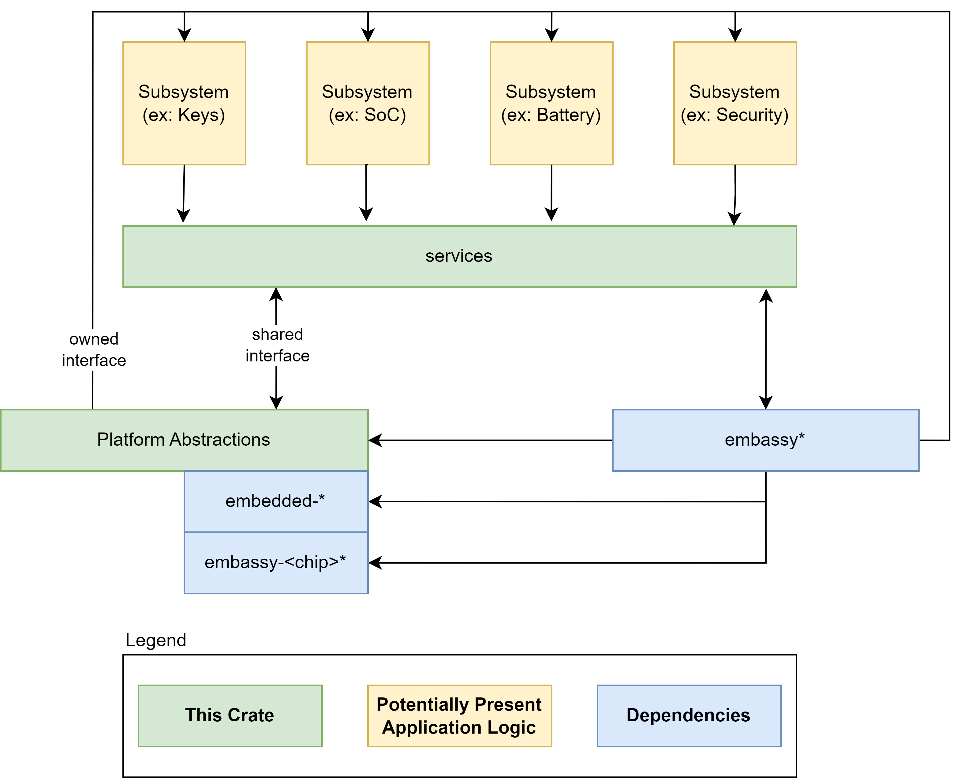
An Embedded Controller is typically a single SOC (System on Chip) design capable of managing a number of low-level tasks.
These individual tasked components of the SOC are represented by the gold boxes in the diagram. The ODP Support for Embedded Controller development is represented in the diagram in the green boxes, whereas third party support libraries are depicted in blue.
Component modularity
A Component can be thought of as a stack of functionality defined by traits (A trait in Rust is analogous to an interface in other common languages).
For the functionality defined by the trait definition to interact with the hardware, there must be a HAL (hardware abstraction layer) defined that implements key actions required by the hardware to conduct these tasks. These HAL actions are then controlled by the functional interface of the component definition.
The component definition is part of a Subsystem of functionality that belongs to a Service.
For example, a Power Policy Service may host several related Subsystems for Battery, Charger, etc. Each of these Subsystems have Controllers to interact with their corresponding components. These Controllers are commanded by the Service their Subsystem belongs to, so for example, the power policy service may interrogate the current charge state of the battery. It does so by interrogating the Subsystem Controller which in turn relies upon the interface defined by the component Trait, which finally calls upon the hardware HAL to retrieve the necessary data from the hardware. This chain of stacked concerns forms a common pattern that allows for agile modularity and flexible portability of components between target contexts.
flowchart TD
    A[e.g. Power Policy Service<br><i>Service initiates query</i>]
    B[Subsystem Controller<br><i>Orchestrates component behavior</i>]
    C[Component Trait Interface<br><i>Defines the functional contract</i>]
    D[HAL Implementation<br><i>Implements trait using hardware-specific logic</i>]
    E[EC / Hardware Access<br><i>Performs actual I/O operations</i>]

    A --> B
    B --> C
    C --> D
    D --> E

    subgraph Service Layer
        A
    end

    subgraph Subsystem Layer
        B
    end

    subgraph Component Layer
        C
        D
    end

    subgraph Hardware Layer
        E
    end
Secure vs Non-Secure
Communication between Subsystems may be considered to be either a "Secure" channel for data communication or a "Non-Secure" channel. An implementation may use more than one transport for different controller and controller service needs.
Data communication with the embedded controller can be considered an owned interface because it is implemented within the EC architecture itself. It may also tie into an external communication bus such as SPI or I2C for data exhanges between other MCUs or the host, but for purposes of communicating between its own subsystems, it is an internally implemented construct.
A "Secure" transport is one that can validate and trust the data from the channel, using cryptographic signatures and hypervisor isolation to insure the integrity of the data exchanged between subsystems. Not all such channels must necessarily be secure, and indeed in some cases depending upon the components used it may not even be possible to secure a channel. The ODP approach is agnostic to these decisions, and can support either or both patterns of implementation.
Depending upon the hardware architecture and available supporting features, a secure channel may incorporate strong isolation between individual component subsystems through memory access and paging mechanisms and/or hypervisor control.
Two similar sounding, but different models become known here. One is SMM, or "System Management Mode". SMM is a high-privilege CPU mode for x86 microcontrollers that EC services can utilize to gain access. To facilitate this, the SMM itself must be secured. This is done as part of the boot time validation and attestation of SMM access policies. With this in place, EC Services may be accessed by employing a SMM interrupt.
For A deeper dive into what SMM is, see How SMM isolation hardens the platform
Another term seen about will be "SMC", or "Secure Memory Control", which is a technology often found in ARM-based architectures. In this scheme, memory is divided into secure and non-secure areas that are mutally exclusive of each other, as well as a narrow section known as "Non-Secure Callable" which is able to call into the "Secure" area from the "Non-Secure" side.
Secure Memory Control concepts are discussed in detail with this document: TrustZone Technology for Armv8-M Architecture
SMM or SMC adoption has design ramifications for EC Services exchanges, but also affects the decisions made around boot firmware, and we'll see these terms again when we look at ODP Patina implementations.
Hypervisor context multiplexing
Another component of a Secure EC design is the use of a hypervisor to constrain the scope of any given component service to a walled-off virtualization context. One such discussion of such use is detailed in this article
The Open Device Partnership defines:
- An "owned interface" that communicates with the underlying hardware via the available data transport .
- We can think of this transport as being a channel that is considered either "Secure" or "Non-Secure".
- This interface supports business logic for operational abstractions and concrete implementations to manipulate or interrogate the connected hardware component.
- The business logic code may rely upon other crates to perform its functions. There are several excellent crates available in the Rust community that may be leveraged, such as Embassy.
- Synchronous and asynchronous patterns are supported.
- No runtime or RTOS dependencies.
An implementation may look a little like this:

EC Services
Embedded controller services are available for the operating system to call for various higher-level purposes dictated by specification. The Windows Operating system defines some of these standard services for its platform.
These service interfaces include those for:
- debug services
- firmware management services
- input management services
- oem services
- power services
- time services
Services may be available for operating systems other than Windows.
OEMs may wish to implement their own services as part of their product differentiation.
EC Service communication protocols
With a communication channel protocol established between OS and EC, operating system agents and applications are able to monitor and operate peripheral controllers from application space.
This scope comes with some obvious security ramifications that must be recognized.
Implementations of ODP may be architected for both Secure and Non-Secure system firmware designs, as previously discussed.

In the diagram above, the dark blue sections are those elements that are part of normal (non-secure) memory space and may be called from a service interface directly. As we can see on the Non-Secure side, the ACPI transport channel has access to the EC component implementations either directly or through the FF-A (Firmware Framework Memory Management Protocol).
FF-A
The Firmware Framework Memory Management Protocol (Spec) describes the relationship of a hypervisor controlling a set of secure memory partitions with configurable access and ownership attributes and the protocol for exchanging information between these virtualized contexts.
FF-A is available for Arm devices only. A common solution for x64 is still in development. For x64 implementations, use of SMM is employed to orchestrate hypervisor access using the [Hafnium] Rust product.
In a Non-Secure implementation without a hyperviser, the ACPI connected components can potentially change the state within any accessible memory space. An implementation with a hypervisor cannot. It may still be considered a "Non-Secure" implementation, however, as the ACPI data itself is unable to be verified for trust.
In a fully "Secure" implementation, controller code is validated at boot time to insure the trust of the data it provides. Additionally, for certain types of data, digital signing and/or encryption may be used on the data exchanged to provide an additional level of trust.
Sample System Implementation
This is short sample implementing a thermal control service interface. This sample assumes one thermal sensor and one thermal control device accessible via ACPI. For an ARM implementation, FF-A and Hafnium is assumed. For x86/x64, an eSPI transport is assumed and direct (Non-Secure) access is made from there.
FFA Device Definition
#![allow(unused)]
fn main() {
Device(\\_SB_.FFA0) {
  Name(_HID, "MSFT000C")
  OperationRegion(AFFH, FFixedHw, 4, 144)
  Field(AFFH, BufferAcc, NoLock, Preserve) { AccessAs(BufferAcc, 0x1), FFAC, 1152 }

  // Other components check this to make sure FFA is available
  Method(AVAL, 0, Serialized) {
    Return(One)
  }

  // Register notification events from FFA
  Method(_RNY, 0, Serialized) {
    Return( Package() {
      Package(0x2) { // Events for Management Service
        ToUUID("330c1273-fde5-4757-9819-5b6539037502"),
        Buffer() {0x1,0x0} // Register event 0x1
      },
      Package(0x2) { // Events for Thermal service
        ToUUID("31f56da7-593c-4d72-a4b3-8fc7171ac073"),
        Buffer() {0x1,0x0,0x2,0x0,0x3,0x0} // Register events 0x1, 0x2, 0x3
      },
      Package(0x2) { // Events for input device
        ToUUID("e3168a99-4a57-4a2b-8c5e-11bcfec73406"),
        Buffer() {0x1,0x0} // Register event 0x1 for LID
      }
    } )
  }

  Method(_NFY, 2, Serialized) {
    // Arg0 == UUID
    // Arg1 == Notify ID
    // Management Service Events

    If(LEqual(ToUUID("330c1273-fde5-4757-9819-5b6539037502"),Arg0)) {
      Switch(Arg1) {
        Case(1) { // Test Notification Event
          Notify(\\_SB.ECT0,0x20)
        }
      }
    }

    // Thermal service events
    If(LEqual(ToUUID("31f56da7-593c-4d72-a4b3-8fc7171ac073"),Arg0)) {
      Switch(Arg1) {
        Case(1) { // Temp crossed low threshold
          Notify(\\_SB.SKIN,0x80)
        }
        Case(2) { // Temp crossed high threshold
          Notify(\\_SB.SKIN,0x81)
        }
        Case(3) { // Critical temperature event
          Notify(\\_SB.SKIN,0x82)
        }
      }
    }

    // Input Device Events
    If(LEqual(ToUUID("e3168a99-4a57-4a2b-8c5e-11bcfec73406"),Arg0)) {
      Switch(Arg1) {
        Case(1) { // LID event
          Notify(\\_SB._LID,0x80)
        }
      }
    }
  }
}
}
Memory Mapped Interface via FFA for UCSI
Note for this implementation of memory mapped interface to work the memory must be marked as reserved by UEFI and not used by the OS and direct access also given to the corresponding service in secure world.
#![allow(unused)]
fn main() {
Device(USBC) {
  Name(_HID,EISAID(“USBC000”))
  Name(_CID,EISAID(“PNP0CA0”))
  Name(_UID,1)
  Name(_DDN, “USB Type-C”)
  Name(_ADR,0x0)
  OperationRegion(USBC, SystemMemory, UCSI_PHYS_MEM, 0x30)
  Field(USBC,AnyAcc,Lock,Preserve)
  {
    // USB C Mailbox Interface
    VERS,16, // PPM-\>OPM Version
    RES, 16, // Reservied
    CCI, 32, // PPM-\>OPM CCI Indicator
    CTRL,64, // OPM-\>PPM Control Messages
    MSGI,128, // OPM-\>PPM Message In
    MSGO,128, // PPM-\>OPM Message Out
  }

  Method(_DSM,4,Serialized,0,UnknownObj, {BuffObj, IntObj,IntObj,PkgObj})
  {

    // Compare passed in UUID to Supported UUID
    If(LEqual(Arg0,ToUUID(“6f8398c2-7ca4-11e4-ad36-631042b5008f”)))
    {
      // Use FFA to send Notification event down to copy data to EC
      If(LEqual(\\_SB.FFA0.AVAL,One)) {
        Name(BUFF, Buffer(144){}) // Create buffer for send/recv data
        CreateByteField(BUFF,0,STAT) // Out – Status for req/rsp
        CreateByteField(BUFF,1,LENG) // In/Out – Bytes in req, updates bytes returned
        CreateField(BUFF,16,128,UUID) // UUID of service
        CreateByteField(BUFF,18, CMDD) // In – First byte of command
        CreateField(BUFF,144,1024,FIFD) // Out – Msg data

        // Create Doorbell Event
        Store(20, LENG)
        Store(0x0, CMDD) // UCSI set doorbell
        Store(ToUUID("daffd814-6eba-4d8c-8a91-bc9bbf4aa301"), UUID)
        Store(Store(BUFF, \_SB_.FFA0.FFAC), BUFF)
      } // End AVAL
    } // End UUID
  } // End DSM
}
}
Thermal ACPI Interface for FFA
This sample code shows one Microsoft Thermal zone for SKIN and then a thermal device THRM for implementing customized IO.
#![allow(unused)]
fn main() {
// Sample Definition of FAN ACPI
Device(SKIN) {
  Name(_HID, "MSFT000A")

  Method(_TMP, 0x0, Serialized) {
    If(LEqual(\\_SB.FFA0.AVAL,One)) {
      Name(BUFF, Buffer(30){})
      CreateByteField(BUFF,0,STAT) // Out – Status for req/rsp
      CreateByteField(BUFF,1,LENG) // In/Out – Bytes in req, updates bytes returned
      CreateField(BUFF,16,128,UUID) // UUID of service
      CreateByteField(BUFF,18,CMDD) // Command register
      CreateByteField(BUFF,19,TZID) // Temp Sensor ID
      CreateDWordField(BUFF,26,RTMP) // Output Data

      Store(20, LENG)
      Store(0x1, CMDD) // EC_THM_GET_TMP
      Store(0x2, TZID) // Temp zone ID for SKIIN
      Store(ToUUID("31f56da7-593c-4d72-a4b3-8fc7171ac073"), UUID)
      Store(Store(BUFF, \\_SB_.FFA0.FFAC), BUFF)

      If(LEqual(STAT,0x0) ) // Check FF-A successful?
      {
        Return (RTMP)
      }
    }
    Return (Ones)
  }

  // Arg0 Temp sensor ID
  // Arg1 Package with Low and High set points
  Method(THRS,0x2, Serialized) {
    If(LEqual(\\_SB.FFA0.AVAL,One)) {
      Name(BUFF, Buffer(32){})
      CreateByteField(BUFF,0,STAT) // Out – Status for req/rsp
      CreateByteField(BUFF,1,LENG) // In/Out – Bytes in req, updates bytes returned
      CreateField(BUFF,16,128,UUID) // UUID of service
      CreateByteField(BUFF,18,CMDD) // Command register
      CreateByteField(BUFF,19,TZID) // Temp Sensor ID
      CreateDwordField(BUFF,20,VTIM) // Timeout
      CreateDwordField(BUFF,24,VLO) // Low Threshold
      CreateDwordField(BUFF,28,VHI) // High Threshold
      CreateDWordField(BUFF,18,TSTS) // Output Data

      Store(ToUUID("31f56da7-593c-4d72-a4b3-8fc7171ac073"), UUID)
      Store(32, LENG)
      Store(0x2, CMDD) // EC_THM_SET_THRS
      Store(Arg0, TZID)
      Store(DeRefOf(Index(Arg1,0)),VTIM)
      Store(DeRefOf(Index(Arg1,1)),VLO)
      Store(DeRefOf(Index(Arg1,2)),VHI)
      Store(Store(BUFF, \\_SB_.FFA0.FFAC), BUFF)

      If(LEqual(STAT,0x0) ) // Check FF-A successful?
      {
        Return (TSTS)
      }
    }
    Return (0x3) // Hardware failure
  }

  // Arg0 GUID 1f0849fc-a845-4fcf-865c-4101bf8e8d79
  // Arg1 Revision
  // Arg2 Function Index
  // Arg3 Function dependent
  Method(_DSM, 0x4, Serialized) {
    If(LEqual(ToUuid("1f0849fc-a845-4fcf-865c-4101bf8e8d79"),Arg0)) {
      Switch(Arg2) {
        Case (0) {
          Return(0x3) // Support Function 0 and Function 1
        }
        Case (1) {
          Return( THRS(0x2, Arg3) ) // Call to function to set threshold
        }
      }
    }
    Return(0x3)
  }
}

Device(THRM) {
  Name(_HID, "MSFT000B")

  // Arg0 Instance ID
  // Arg1 UUID of variable
  // Return (Status,Value)
  Method(GVAR,2,Serialized) {
    If(LEqual(\\_SB.FFA0.AVAL,One)) {
      Name(BUFF, Buffer(38){})
      CreateByteField(BUFF,0,STAT) // Out – Status for req/rsp
      CreateByteField(BUFF,1,LENG) // In/Out – Bytes in req, updates bytes returned
      CreateField(BUFF,16,128,UUID) // UUID of service
      CreateByteField(BUFF,18,CMDD) // Command register
      CreateByteField(BUFF,19,INST) // Instance ID
      CreateWordField(BUFF,20,VLEN) // 16-bit variable length
      CreateField(BUFF,176,128,VUID) // UUID of variable to read
      CreateField(BUFF,208,64,RVAL) // Output Data

      Store(ToUUID("31f56da7-593c-4d72-a4b3-8fc7171ac073"), UUID)
      Store(38, LENG)
      Store(0x5, CMDD) // EC_THM_GET_VAR
      Store(Arg0,INST) // Save instance ID
      Store(4,VLEN) // Variable is always DWORD here
      Store(Arg1, VUID)
      Store(Store(BUFF, \\_SB_.FFA0.FFAC), BUFF)

      If(LEqual(STAT,0x0) ) // Check FF-A successful?
      {
        Return (RVAL)
      }
    }
    Return (0x3)
  }

  // Arg0 Instance ID
  // Arg1 UUID of variable
  // Return (Status,Value)
  Method(SVAR,3,Serialized) {
    If(LEqual(\\_SB.FFA0.AVAL,One)) {
      Name(BUFF, Buffer(42){})
      CreateByteField(BUFF,0,STAT) // Out – Status for req/rsp
      CreateByteField(BUFF,1,LENG) // In/Out – Bytes in req, updates bytes returned
      CreateField(BUFF,16,128,UUID) // UUID of service
      CreateByteField(BUFF,18,CMDD) // Command register
      CreateByteField(BUFF,19,INST) // Instance ID
      CreateWordField(BUFF,20,VLEN) // 16-bit variable length
      CreateField(BUFF,176,128,VUID) // UUID of variable to read
      CreateDwordField(BUFF,38,DVAL) // Data value
      CreateField(BUFF,208,32,RVAL) // Ouput Data

      Store(ToUUID("31f56da7-593c-4d72-a4b3-8fc7171ac073"), UUID)
      Store(42, LENG)
      Store(0x6, CMDD) // EC_THM_SET_VAR
      Store(Arg0,INST) // Save instance ID
      Store(4,VLEN) // Variable is always DWORD here
      Store(Arg1, VUID)
      Store(Arg2,DVAL)
      Store(Store(BUFF, \\_SB_.FFA0.FFAC), BUFF)

      If(LEqual(STAT,0x0) ) // Check FF-A successful?
      {
      Return (RVAL)
      }
    }
    Return (0x3)
  }

  // Arg0 GUID
  // 07ff6382-e29a-47c9-ac87-e79dad71dd82 - Input
  // d9b9b7f3-2a3e-4064-8841-cb13d317669e - Output
  // Arg1 Revision
  // Arg2 Function Index
  // Arg3 Function dependent
  Method(_DSM, 0x4, Serialized) {
    // Input Variable
    If(LEqual(ToUuid("07ff6382-e29a-47c9-ac87-e79dad71dd82"),Arg0)) {
      Switch(Arg2) {
        Case(0) {
          // We support function 0-3
          Return(0xf)
        }
        Case(1) {
          Return(GVAR(1,ToUuid("ba17b567-c368-48d5-bc6f-a312a41583c1"))) // OnTemp
        }
        Case(2) {
          Return(GVAR(1,ToUuid("3a62688c-d95b-4d2d-bacc-90d7a5816bcd"))) // RampTemp
        }
        Case(3) {
          Return(GVAR(1,ToUuid("dcb758b1-f0fd-4ec7-b2c0-ef1e2a547b76"))) // MaxTemp
        }
      }
      Return(0x1)
    }

    // Output Variable
    If(LEqual(ToUuid("d9b9b7f3-2a3e-4064-8841-cb13d317669e"),Arg0)) {
      Switch(Arg2) {
        Case(0) {
          // We support function 0-3
          Return(0xf)
        }
        Case(1) {
          Return(SVAR(1,ToUuid("ba17b567-c368-48d5-bc6f-a312a41583c1"),Arg3)) // OnTemp
        }
        Case(2) {
          Return(SVAR(1,ToUuid("3a62688c-d95b-4d2d-bacc-90d7a5816bcd"),Arg3)) // RampTemp
        }
        Case(3) {
          Return(SVAR(1,ToUuid("dcb758b1-f0fd-4ec7-b2c0-ef1e2a547b76"),Arg3)) // MaxTemp
        }
      }
    }
    Return (0x1)
  }
}
}
Call Flows for secure and non-secure Implementation
Depending on system requirements the ACPI calls may go directly to the EC or through secure world then through to EC.
When using non-secure interface the ACPI functions must define protocol level which is the Embedded controller for eSPI. For I2C/I3C or SPI interfaces the corresponding ACPI device must define the bus dependency and build the packet directly that is sent to the EC.
For secure communication all data is sent to the secure world via FF-A commands described in this document and the actual bus protocol and data sent to the EC is defined in the secure world in Hafnium. All support for FF-A is inboxed in the OS by default so EC communication will always work in any environment. However, FF-A is not supported in x86/x64 platforms so direct EC communication must be used on these platforms.
Non-Secure eSPI Access
This call flow assumes using Embedded controller definition with independent ACPI functions for MPTF support
Non-Secure eSPI READ
#![allow(unused)]
fn main() {
Device(EC0) {
  Name(_HID, EISAID("PNP0C09")) // ID for this EC

  // current resource description for this EC
  Name(_CRS, ResourceTemplate() {
    Memory32Fixed (ReadWrite, 0x100000, 0x10) // Used for simulated port access
    Memory32Fixed (ReadWrite, 0x100010, 0x10)
    // Interrupt defined for eSPI event signalling
    GpioInt(Edge, ActiveHigh, ExclusiveAndWake,PullUp 0,"\\_SB.GPI2"){43}
  })

  Name(_GPE, 0) // GPE index for this EC

  // create EC's region and field for thermal support
  OperationRegion(EC0, EmbeddedControl, 0, 0xFF)
  Field(EC0, ByteAcc, Lock, Preserve) {
    MODE, 1, // thermal policy (quiet/perform)
    FAN, 1, // fan power (on/off)
    , 6, // reserved
    TMP, 16, // current temp
    AC0, 16, // active cooling temp (fan high)
    , 16, // reserved
    PSV, 16, // passive cooling temp
    HOT 16, // critical S4 temp
    CRT, 16 // critical temp
    BST1, 32, // Battery State
    BST2, 32, // Battery Present Rate
    BST3, 32, // Battery Remaining capacity
    BST4, 32, // Battery Present Voltage
  }

  Method (_BST) {
    Name (BSTD, Package (0x4)
    {
      \\_SB.PCI0.ISA0.EC0.BST1, // Battery State
      \\_SB.PCI0.ISA0.EC0.BST2, // Battery Present Rate
      \\_SB.PCI0.ISA0.EC0.BST3, // Battery Remaining Capacity
      \\_SB.PCI0.ISA0.EC0.BST4, // Battery Present Voltage
    })
    Return(BSTD)
  }
}
}
sequenceDiagram
  OSPM->>ACPI: call _BST method
  ACPI->>ACPI: Map to EC0 fields in EC operation Region
  ACPI->>ACPI: EC0 accesses change to eSPI Peripheral accesses
  ACPI->>eSPI: Each field acccess changed to peripheral read/write
  ACPI->>ACPI: ACI handles SCI, port IO, MMIO, serialized
  ACPI->>ACPI: eSPI read/writes complete
  ACPI->>ACPI: Data is reorganized to _BST structure
  ACPI->>OSPM: Return _BST structure with status
Non-Secure eSPI Notifications
All interrupts are handled by the ACPI driver. When EC needs to send a notification event the GPIO is asserted and traps into IRQ. ACPI driver reads the EC_SC status register to determine if an SCI is pending. DPC callback calls and reads the EC_DATA port to determine the _Qxx event that is pending. Based on the event that is determined by ACPI the corresponding _Qxx event function is called.
#![allow(unused)]
fn main() {
Method (_Q07) {
  // Take action for event 7
  Notify(\\_SB._LID, 0x80)
}
}
sequenceDiagram
  EC->>SCI ISR: EC asserts alert (IRQ)
  SCI ISR->>SCI DPC: Schedule DPC if EC_SC indicates SCI
  SCI DPC->>EC: Read EC_DATA to determine event
  EC->>SCI DPC: Send Qxx event
  SCI DPC->>ACPI: Call _Qxx function in EC0
Secure eSPI Access
The following flow assumes ARM platform using FF-A for secure calls. Note if you want to use the same EC firmware on both platforms with secure and non-secure access the EC_BAT_GET_BST in this case should be convert to a peripheral access with the same IO port and offset as non-secure definition.
Secure eSPI READ
#![allow(unused)]
fn main() {
Method (_BST) {
  // Check to make sure FFA is available and not unloaded
  If(LEqual(\\_SB.FFA0.AVAL,One)) {
    Name(BUFF, Buffer(32){}) // Create buffer for send/recv data
    CreateByteField(BUFF,0,STAT) // Out – Status for req/rsp
    CreateByteField(BUFF,1,LENG) // In/Out – Bytes in req, updates bytes returned
    CreateField(BUFF,16,128,UUID) // UUID of service
    CreateByteField(BUFF,18, CMDD) // In – First byte of command
    CreateDwordField(BUFF,19, BMA1) // In – Averaging Interval
    CreateField(BUFF,144,128,BSTD) // Out – 4 DWord BST data

    Store(ToUUID("25cb5207-ac36-427d-aaef-3aa78877d27e"), UUID) // Battery
    Store(42, LENG)
    Store(0x6, CMDD) // EC_BAT_GET_BST
    Store(Store(BUFF, \\_SB_.FFA0.FFAC), BUFF)

    If(LEqual(STAT,0x0) ) // Check FF-A successful?
    {
    Return (BMAD)
    }
  }
  Return(Zero)
}
}
sequenceDiagram
 OSPM->>ACPI: call_BST method
 ACPI->>FFA: Send EC_BAT_GET_BST_request
 FFA->>EC Service: Forward EC_BAT_GET_BST_request
 EC Service->>EC Service: Convert to eSPI peripheral read/write
 EC Service->>eSPI: send peripheral read/write access
 EC Service->>FFA: FFA_YIELD (as needed)
 FFA->>EC Service: FFA_RESUME (check for complete)
 eSPI->>EC Service: Return peripheral read data
 EC Service->>EC Service: Convert to EC_BAT_GET_BST response
 EC Service->>FFA: FFA response to original request
 FFA->>ACPI: return FFA status and _BST response
 ACPI->OSPM: return _BST structure
Secure eSPI Notification
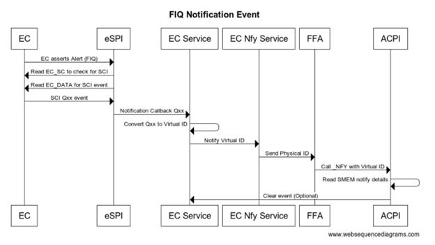
When EC communication is done through Secure world we assert FIQ which is handled as eSPI interrupt. eSPI driver reads EC_SC and EC_DATA to retrieve the notification event details. On Non-secure implementation ACPI converts this to Qxx callback. On secure platform this is converted to a virtual ID and sent back to the OS via _NFY callback and a virtual ID.
#![allow(unused)]
fn main() {
Method(_NFY, 2, Serialized) {
  // Arg0 == UUID
  // Arg1 == Notify ID
  If(LEqual(ToUUID("25cb5207-ac36-427d-aaef-3aa78877d27e"),Arg0)) {
    If(LEqual(0x2,Arg1)) {
      Store(Arg1, \\_SB.ECT0.NEVT)
      Notify(\\_SB._LID, 0x80)
    }
  }
}
}
sequenceDiagram
   EC->>eSPI: EC asserts Alert (FIQ)
   eSPI->>EC: Read EC_SC to check for SCI
   eSPI->>EC: Read EC_DATA for SCI event
   EC->>eSPI: SCI Qxx event

   eSPI->>EC Service: Notification callback Qxx
   EC Service->>EC Service: Convert qxx to Virtual ID
   EC Service->>EC Nfy Service: Notify Virtual ID
   EC Nfy Service->>FFA:Send Physical ID
   FFA->>ACPI:Call_NFY with Virtual ID
   ACPI->>ACPI: Read SMEM notify details
   ACPI--)EC Service: Clear event (optional)
Legacy EC Interface
ACPI specification has a definition for an embedded controller, however this implementation is tied very closely to the eSPI bus and x86 architecture.
The following is an example of legacy EC interface definition from ACPI
11.7. Thermal Zone Examples — ACPI Specification 6.4 documentation
#![allow(unused)]
fn main() {
Scope(\\_SB.PCI0.ISA0) {
  Device(EC0) {
    Name(_HID, EISAID("PNP0C09")) // ID for this EC

    // current resource description for this EC
    Name(_CRS, ResourceTemplate() {
      IO(Decode16,0x62,0x62,0,1)
      IO(Decode16,0x66,0x66,0,1)
    })

    Name(_GPE, 0) // GPE index for this EC

    // create EC's region and field for thermal support
    OperationRegion(EC0, EmbeddedControl, 0, 0xFF)
    Field(EC0, ByteAcc, Lock, Preserve) {
      MODE, 1, // thermal policy (quiet/perform)
      FAN, 1, // fan power (on/off)
      , 6, // reserved
      TMP, 16, // current temp
      AC0, 16, // active cooling temp (fan high)
      , 16, // reserved
      PSV, 16, // passive cooling temp
      HOT 16, // critical S4 temp
      CRT, 16 // critical temp
    }

    // following is a method that OSPM will schedule after
    // it receives an SCI and queries the EC to receive value 7
    Method(_Q07) {
      Notify (\\_SB.PCI0.ISA0.EC0.TZ0, 0x80)
    } // end of Notify method

    // fan cooling on/off - engaged at AC0 temp
    PowerResource(PFAN, 0, 0) {
      Method(_STA) { Return (\\_SB.PCI0.ISA0.EC0.FAN) } // check power state
      Method(_ON) { Store (One, \\\\_SB.PCI0.ISA0.EC0.FAN) } // turn on fan
      Method(_OFF) { Store ( Zero, \\\\_SB.PCI0.ISA0.EC0.FAN) }// turn off
fan
    }

    // Create FAN device object
    Device (FAN) {
    // Device ID for the FAN
    Name(_HID, EISAID("PNP0C0B"))
    // list power resource for the fan
    Name(_PR0, Package(){PFAN})
    }

    // create a thermal zone
    ThermalZone (TZ0) {
      Method(_TMP) { Return (\\_SB.PCI0.ISA0.EC0.TMP )} // get current temp
      Method(_AC0) { Return (\\_SB.PCI0.ISA0.EC0.AC0) } // fan high temp
      Name(_AL0, Package(){\\_SB.PCI0.ISA0.EC0.FAN}) // fan is act cool dev
      Method(_PSV) { Return (\\_SB.PCI0.ISA0.EC0.PSV) } // passive cooling
temp
      Name(_PSL, Package (){\\_SB.CPU0}) // passive cooling devices
      Method(_HOT) { Return (\\_SB.PCI0.ISA0.EC0.HOT) } // get critical S4
temp
      Method(_CRT) { Return (\\_SB.PCI0.ISA0.EC0.CRT) } // get critical temp
      Method(_SCP, 1) { Store (Arg1, \\\\_SB.PCI0.ISA0.EC0.MODE) } // set
cooling mode

      Name(_TSP, 150) // passive sampling = 15 sec
      Name(_TZP, 0) // polling not required
      Name (_STR, Unicode ("System thermal zone"))
    } // end of TZ0
  } // end of ECO
} // end of \\\\_SB.PCI0.ISA0 scope-
}
On platforms that do not support IO port access there is an option to define MMIO regions to simulate the IO port transactions.
In the above example you can see that the operation region directly maps to features on the EC and you can change the EC behavior by writing to a byte in the region or reading the latest data from the EC.
For a system with the EC connected via eSPI and that needs a simple non-secure interface to the EC the above mapping works very well and keeps the code simple. The eSPI protocol itself has details on port accesses and uses the peripheral channel to easily read/write memory mapped regions.
As the EC features evolve there are several requirements that do no work well with this interface:
-
Different buses such as I3C, SPI, UART target a packet request/response rather than a memory mapped interface
-
Protected or restricted access and validation of request/response
-
Firmware update, large data driven requests that require larger data response the 256-byte region is limited
-
Discoverability of features available and OEM customizations
-
Out of order completion of requests, concurrency, routing and priority handling
As we try to address these limitations and move to a more packet based protocol described in this document. The following section covers details on how to adopt existing operation region to new ACPI functionality.
Adopting EC Operation Region
The new OS frameworks such as MPTF still use ACPI methods as primary interface. Instead of defining devices such as FAN or ThermalZone in the EC region you can simply define the EC region itself and then map all the other ACPI functions to operate on this region. This will allow you to maintain backwards compatibility with existing EC definitions.
#![allow(unused)]
fn main() {
Device(EC0) {
  Name(_HID, EISAID("PNP0C09")) // ID for this EC
  // current resource description for this EC
  Name(_CRS, ResourceTemplate() {
    IO(Decode16,0x62,0x62,0,1)
    IO(Decode16,0x66,0x66,0,1)
  })

  // create EC's region and field for thermal support
  OperationRegion(EC0, EmbeddedControl, 0, 0xFF)
  Field(EC0, ByteAcc, Lock, Preserve) {
    MODE, 1, // thermal policy (quiet/perform)
    FAN, 1, // fan power (on/off)
    , 6, // reserved
    TMP, 16, // current temp
    AC0, 16, // active cooling temp (fan high)
    , 16, // reserved
    PSV, 16, // passive cooling temp
    HOT 16, // critical S4 temp
    CRT, 16 // critical temp
  }
}

Device(SKIN) {
  Name(_HID, "MSFT000A") // New MPTF HID Temperature Device
  Method(_TMP, 0x0, Serialized) {
      Return( \\_SB.PCI0.ISA0.EC0.TMP)
  }
}
}
For more complicated functions that take a package some of the data may be constructed within ACPI and some of the data pulled from the OperationRegion. For example BIX for battery information may have a combination of static and dynamic data like this:
#![allow(unused)]
fn main() {
Method (_BIX) {
  Name (BAT0, Package (0x12)
  {
    0x01, // Revision
    0x02, // Power Unit
    0x03, // Design Capacity
    \\_SB.PCI0.ISA0.EC0.BFCC, // Last Full Charge Capacity
    0x05, // Battery Technology
    0x06, // Design Voltage
    0x07, // Design capacity of Warning
    0x08, // Design Capacity of Low
    \\_SB.PCI0.ISA0.EC0.BCYL, // Cycle Count
    0x0A, // Measurement Accuracy
    0x0B, // Max Sampling Time
    0x0C, // Min Sampling Time
    0x0D, // Max Averaging Interval
    0x0E, // Min Averaging Interval
    0x0F, // Battery Capacity Granularity 1
    0x10, // Battery Capacity Granularity 2
    "Model123", // Model Number
    "Serial456", // Serial Number
    "Li-Ion", // Battery Type
    "OEMName" // OEM Information
  })
  Return(BAT0)
}
}
Limitations for using Legacy EC
Before using the Legacy EC definition OEM’s should be aware of several use cases that may limit you ability to use it.
ACPI support for eSPI master
In the case of Legacy EC the communication to the EC is accomplished directly by the ACPI driver using PORT IO and eSPI Peripheral Bus commands. On ARM platforms there is no PORT IO and these must be substituted with MMIO regions. The ACPI driver needs changes to support MMIO which is being evaluated and support is not yet available. Some Silicon Vendors also do not implement the full eSPI specification and as such the ACPI driver cannot handle all the communication needs. On these platforms using Legacy EC interface is not an option.
Security of eSPI bus
When non-secure world is given access to the eSPI bus it can send commands to device on that bus. Some HW designs have the TPM or SPINOR on the same physical bus as the EC. On these designs allowing non-secure world to directly sends commands to EC can break the security requirements of other devices on the bus. In these cases the eSPI communication must be done in the secure world over FF-A as covered in this document and not use the Legacy EC channel. Since non-secure world has complete access to the EC operation region there is no chance for encryption of data. All data in the operation region is considered non-secure.
Functional limitations of Legacy EC
The peripheral region that is mapped in the Legacy EC in ACPI is limited to 256 bytes and notification events to the ones that are defined and handled in ACPI driver. To create custom solutions, send large packets or support encryption of data the Legacy EC interface has limitations in this area.
Secure EC Services Overview
In this section we review a system design where the EC communication is in the secure world running in a dedicated SP. In a system without secure world or where communication to EC is not desired to be secure all the ACPI functions can be mapped directly to data from the EC operation region.
The following github projects provide sample implementations of this interface:
ACPI EC samples, Kernel mode test driver, User mode test driver
Sample Secure Partition Service for EC services in RUST
RUST crate for FFA implementation in secure partition
The following GUID’s have been designed to represent each service operating in the secure partition for EC.
| EC Service Name | Service GUID | Description | EC_SVC_MANAGEMENT | 330c1273-fde5-4757-9819-5b6539037502 | Used to query EC functionality, Board info, version, security state, FW update | EC_SVC_POWER | 7157addf-2fbe-4c63-ae95-efac16e3b01c | Handles general power related requests and OS Sx state transition state notification | EC_SVC_BATTERY | 25cb5207-ac36-427d-aaef-3aa78877d27e | Handles battery info, status, charging | EC_SVC_THERMAL | 31f56da7-593c-4d72-a4b3-8fc7171ac073 | Handles thermal requests for skin and other thermal events | EC_SVC_UCSI | 65467f50-827f-4e4f-8770-dbf4c3f77f45 | Handles PD notifications and calls to UCSI interface | EC_SVC_INPUT | e3168a99-4a57-4a2b-8c5e-11bcfec73406 | Handles wake events, power key, lid, input devices (HID separate instance) | EC_SVC_TIME_ALARM | 23ea63ed-b593-46ea-b027-8924df88e92f | Handles RTC and wake timers. | EC_SVC_DEBUG | 0bd66c7c-a288-48a6-afc8-e2200c03eb62 | Used for telemetry, debug control, recovery modes, logs, etc | EC_SVC_TEST | 6c44c879-d0bc-41d3-bef6-60432182dfe6 | Used to send commands for manufacturing/factory test | EC_SVC_OEM1 | 9a8a1e88-a880-447c-830d-6d764e9172bb | Sample OEM custom service and example piping of events |
|---|
FFA Overview
This section covers the components involved in sending a command to EC through the FFA flow in windows. This path is specific to ARM devices and a common solution with x64 is still being worked out. Those will continue through the non-secure OperationRegion in the near term.

ARM has a standard for calling into the secure world through SMC’s and targeting a particular service running in secure world via a UUID. The full specification and details can be found here: Firmware Framework for A-Profile
The windows kernel provides native ability for ACPI to directly send and receive FFA commands. It also provides a driver ffadrv.sys to expose a DDI that allows other drivers to directly send/receive FFA commands without needing to go through ACPI.
Hyper-V forwards the SMC’s through to EL3 to Hafnium which then uses the UUID to route the request to the correct SP and service. From the corresponding EC service it then calls into the eSPI or underlying transport layer to send and receive the request to the physical EC.
FFA Device Definition
The FFA device is loaded from ACPI during boot and as such requires a Device entry in ACPI
#![allow(unused)]
fn main() {
  Name(_HID, "MSFT000C")

  OperationRegion(AFFH, FFixedHw, 4, 144)
  Field(AFFH, BufferAcc, NoLock, Preserve) { AccessAs(BufferAcc, 0x1), FFAC, 1152 }


  Name(_DSD, Package() {
      ToUUID("daffd814-6eba-4d8c-8a91-bc9bbf4aa301"), //Device Prop UUID
      Package() {
        Package(2) {
          "arm-arml0002-ffa-ntf-bind",
          Package() {
              1, // Revision
              2, // Count of following packages
              Package () {
                     ToUUID("330c1273-fde5-4757-9819-5b6539037502"), // Service1 UUID
                     Package () {
                          0x01,     //Cookie1 (UINT32)
                          0x07,     //Cookie2
                      }
              },
              Package () {
                     ToUUID("b510b3a3-59f6-4054-ba7a-ff2eb1eac765"), // Service2 UUID
                     Package () {
                          0x01,     //Cookie1
                          0x03,     //Cookie2
                      }
             }
         }
      }
    }
  }) // _DSD()

  Method(_DSM, 0x4, NotSerialized)
  {
    // Arg0 - UUID
    // Arg1 - Revision
    // Arg2: Function Index
    //         0 - Query
    //         1 - Notify
    //         2 - binding failure
    //         3 - infra failure
    // Arg3 - Data

    //
    // Device specific method used to query
    // configuration data. See ACPI 5.0 specification
    // for further details.
    //
    If(LEqual(Arg0, Buffer(0x10) {
        //
        // UUID: {7681541E-8827-4239-8D9D-36BE7FE12542}
        //
        0x1e, 0x54, 0x81, 0x76, 0x27, 0x88, 0x39, 0x42, 0x8d, 0x9d, 0x36, 0xbe, 0x7f, 0xe1, 0x25, 0x42
      }))
    {
      // Query Function
      If(LEqual(Arg2, Zero))
      {
        Return(Buffer(One) { 0x03 }) // Bitmask Query + Notify
      }

      // Notify Function
      If(LEqual(Arg2, One))
      {
        // Arg3 - Package {UUID, Cookie}
        Store(Index(Arg3,1), \_SB.ECT0.NEVT )
        Return(Zero)
      }
    } Else {
      Return(Buffer(One) { 0x00 })
    }
  }

  Method(AVAL,0x0, Serialized)
  {
    Return(One)
  }
}
}
HID definition
The _HID “MSFT000C” is reserved for FFA devices. Defining this HID for your device will cause the FFA interface for the OS to be loaded on this device.
Operation Region Definition
The operation region is marked as FFixedHw type 4 which lets the ACPI interpreter know that any read/write to this region requires special handling. The length is 144 bytes because this region operates on registers X0-X17 each of which are 8 bytes 18*8 = 144 bytes. This is mapped to FFAC is 1152 bits (144*8) and this field is where we act upon.
#![allow(unused)]
fn main() {
OperationRegion(AFFH, FFixedHw, 4, 144)
Field(AFFH, BufferAcc, NoLock, Preserve) { AccessAs(BufferAcc, 0x1),FFAC, 1152 }
}
When reading and writing from this operation region the FFA driver does some underlying mapping for X0-X3
X0 = 0xc400008d // FFA_DIRECT_REQ2
X1 = (Receiver Endpoint ID) | (Sender Endpoint ID \<\< 16)
X2/X3 = UUID
The following is the format of the request and response packets that are sent via ACPI
#![allow(unused)]
fn main() {
FFA_REQ_PACKET
{
  uint8 status; // Not used just populated so commands are symmetric
  uint8 length; // Number of bytes in rawdata
  uint128 UUID;
  uint8 reqdata[];
}

FFA_RSP_PACKET
{
  uint8 status; // Status from ACPI if FFA command was sent successfully
  uint8 length;
  uint128 UUID;
  uint64 ffa_status; // Status returned from the service of the FFA command
  uint8 rspdata[];
}

CreateByteField(BUFF,0,STAT) // Out – Status for req/rsp
CreateByteField(BUFF,1,LENG) // In/Out – Bytes in req, updates bytes returned
CreateField(BUFF,16,128,UUID) // In/Out - UUID of service
CreateDwordField(BUFF,18,FFST)// Out - FFA command status
}
Register Notification
During FFA driver initialization it calls into secure world to get a list of all available services for each secure partition. After this we send a NOTIFICATION_REGISTRATION request to each SP that has a service which registers for notification events
#![allow(unused)]
fn main() {
  Name(_DSD, Package() {
      ToUUID("daffd814-6eba-4d8c-8a91-bc9bbf4aa301"), //Device Prop UUID
      Package() {
        Package(2) {
          "arm-arml0002-ffa-ntf-bind",
          Package() {
              1, // Revision
              1, // Count of following packages
              Package () {
                     ToUUID("330c1273-fde5-4757-9819-5b6539037502"), // Service1 UUID
                     Package () {
                          0x01,     //Cookie1 (UINT32)
                          0x07,     //Cookie2
                      }
              },
         }
      }
    }
  }) // _DSD()
}

In the above example we indicate that the OS will handle 2 different notification events for UUID 330c1273-fde5-4757-9819-5b6539037502 which is our EC management UUID. FFA knows which secure partition this maps to based on the list of services for each SP it has retrieved. Rather than having to keep track of all the physical bits in the bitmask that are used the FFA driver keeps track of this and allows each service to create a list of virtual ID’s they need to handle. The FFA driver then maps this to one of the available bits in the hardware bitmask and passes this mapping down to the notification service running in a given SP.
Input
| Parameter | Register | Value | Function | X4 | 0x1 | UUID Lo | X5 | Bytes [0..7] for the service UUID. | UUID Hi | X6 | Bytes [8..16] for the service UUID. | Mappings Count | X7 | The number of notification mappings | Notification Mapping1 | X8 | Bits [0..16] – Notification ID. --> 0,1,2,3,...
Bits [16..32] – Notification Bitmap bit number (0-383). |
Notification Mapping2 | X9 | Bits [0..16] – Notification ID. --> 0,1,2,3,...
Bits [16..32] – Notification Bitmap bit number (0-383).
|
... | ... | ... |
|---|
Output
| Parameter | Register | Value |
|---|---|---|
| Result | X4 | 0 on success. Otherwise, Failure |
Note this NOTIFICATION_REGISTER request is sent to the Notification Service UUID in the SP. The UUID of the service that the notifications are for are stored in X5/X6 registers shown above.
The UUID for notification service is {B510B3A3-59F6-4054-BA7A-FF2EB1EAC765} which is stored in X2/X3.
Notification Events
All notification events sent from all secure partitions are passed back through the FFA driver. The notification calls the _DSM method. Function 0 is always a bitmap of all the other functions supported. We must support at least a minium of the Query and Notify. The UUID is stored in Arg0 and the notification cookie is stored in Arg3 when Arg2 is 11.
#![allow(unused)]
fn main() {
  Method(_DSM, 0x4, NotSerialized)
  {
    // Arg0 - UUID
    // Arg1 - Revision
    // Arg2: Function Index
    //         0 - Query
    //         1 - Notify
    //         2 - binding failure
    //         3 - infra failure
    // Arg3 - Data

    //
    // Device specific method used to query
    // configuration data. See ACPI 5.0 specification
    // for further details.
    //
    If(LEqual(Arg0, Buffer(0x10) {
        //
        // UUID: {7681541E-8827-4239-8D9D-36BE7FE12542}
        //
        0x1e, 0x54, 0x81, 0x76, 0x27, 0x88, 0x39, 0x42, 0x8d, 0x9d, 0x36, 0xbe, 0x7f, 0xe1, 0x25, 0x42
      }))
    {
      // Query Function
      If(LEqual(Arg2, Zero))
      {
        Return(Buffer(One) { 0x03 }) // Bitmask Query + Notify
      }

      // Notify Function
      If(LEqual(Arg2, One))
      {
        // Arg3 - Package {UUID, Cookie}
        Store(Index(Arg3,1), \_SB.ECT0.NEVT )
        Return(Zero)
      }
    } Else {
      Return(Buffer(One) { 0x00 })
    }
  }
}
The following is the call flow showing a secure interrupt arriving to the EC service which results in a notification back to ACPI. The notification payload can optionally be written to a shared buffer or ACPI can make another call back into EC service to retrieve the notification details.
The _NFY only contains the ID of the notification and no other payload, so both ACPI and the EC service must be designed either with shared memory buffer or a further notify data packet.

Runtime Requests
During runtime the non-secure side uses FFA_MSG_SEND_DIRECT_REQ2 requests to send requests to a given service within an SP. Any request that is expected to take longer than 500 uSec should yield control back to the OS by calling FFA_YIELD within the service. When FFA_YIELD is called it will return control back to the OS to continue executing but the corresponding ACPI thread will be blocked until the original FFA request completes with DIRECT_RSP2. Note this creates a polling type interface where the OS will resume the SP thread after the timeout specified. The following is sample call sequence.

FFA Example Data Flow
For an example let’s take the battery status request _BST and follow data through.

#![allow(unused)]
fn main() {
FFA_REQ_PACKET req = {
  0x0, // Initialize to no error
  0x1, // Only 1 byte of data is sent after the header
  {0x25,0xcb,0x52,0x07,0xac,0x36,0x42,0x7d,0xaa,0xef,0x3a,0xa7,0x88,0x77,0xd2,0x7e},
  0x2 // EC_BAT_GET_BST
}
}
The equivalent to write this data into a BUFF in ACPI is as follows
#![allow(unused)]
fn main() {
Name(BUFF, Buffer(32){}) // Create buffer for send/recv data
CreateByteField(BUFF,0,STAT) // Out – Status for req/rsp
CreateByteField(BUFF,1,LENG) // In/Out – Bytes in req, updates bytes returned
CreateField(BUFF,16,128,UUID) // UUID of service
CreateByteField(BUFF,18, CMDD) // In – First byte of command
CreateField(BUFF,144,128,BSTD) // Out – Raw data response 4 DWords
Store(20,LENG)
Store(0x2, CMDD)
Store(ToUUID ("25cb5207-ac36-427d-aaef-3aa78877d27e"), UUID)
Store(Store(BUFF, \\_SB_.FFA0.FFAC), BUFF)
}
The ACPI interpreter when walking through this code creates a buffer and populates the data into buffer. The last line indicates to send this buffer over FFA interface.
ACPI calls into the FFA interface to send the data over to the secure world EC Service
typedef struct _FFA_INTERFACE {
    ULONG Version;
    PFFA_MSG_SEND_DIRECT_REQ2 SendDirectReq2;
} FFA_INTERFACE, \*PFFA_INTERFACE;
FFA Parsing
FFA is in charge of sending the SMC over to the secure world and routing to the correct service based on UUID.

X0 = SEND_DIRECT_REQ2 SMC command ID
X1 = Source ID and Destination ID
X2 = UUID Low
X3 = UUID High
X4-X17 = rawdata
Note: The status and length are not passed through to the secure world they are consumed only be ACPI.
HyperV and Monitor have a chance to filter or deny the request, but in general just pass the SMC request through to Hafnium
Hafnium extracts the data from the registers into an sp_msg structure which is directly mapping contents from x0-x17 into these fields.
#![allow(unused)]
fn main() {
pub struct FfaParams {
    pub x0: u64,
    pub x1: u64,
    pub x2: u64,
    pub x3: u64,
    pub x4: u64,
    pub x5: u64,
    pub x6: u64,
    pub x7: u64,
    pub x8: u64,
    pub x9: u64,
    pub x10: u64,
    pub x11: u64,
    pub x12: u64,
    pub x13: u64,
    pub x14: u64,
    pub x15: u64,
    pub x16: u64,
    pub x17: u64,
}
}
In our SP we receive the raw FfaParams structure and we convert this to an FfaMsg using our translator. This pulls out the function_id, source_id, destination_id and uuid.
#![allow(unused)]
fn main() {
fn from(params: FfaParams) -> FfaMsg {
  FfaMsg {
    function_id: params.x0,              // Function id is in lower 32 bits of x0
    source_id: (params.x1 >> 16) as u16, // Source in upper 16 bits
    destination_id: params.x1 as u16,    // Destination in lower 16 bits
    uuid: u64_to_uuid(params.x2, params.x3),
    args64: [
      params.x4, params.x5, params.x6, params.x7, params.x8, params.x9, params.x10,
      params.x11, params.x12, params.x13, params.x14, params.x15, params.x16, params.x17,
            ],
  }
}
}
The destination_id is used to route the message to the correct SP, this is based on the ID field in the DTS description file. Eg: id = <0x8001>;
EC Service Parsing
Within the EC partition there are several services that run, the routing of the FF-A request to the correct services is done by the main message handling loop for the secure partition. After receiving a message we call into ffa_msg_handler and based on the UUID send it to the corresponding service to handle the message.
#![allow(unused)]
fn main() {
let mut next_msg = ffa.msg_wait();
loop {
  match next_msg {
    Ok(ffamsg) => match ffa_msg_handler(&ffamsg) {
      Ok(msg) => next_msg = ffa.msg_resp(\&msg),
      Err(_e) => panic!("Failed to handle FFA msg"),
    },
    Err(_e) => {
      panic!("Error executing msg_wait");
    }
   }
}
}
The main message loop gets the response back from ffa_msg_handler and returns to non-secure world so the next incoming message after the response is a new message to handle.
#![allow(unused)]
fn main() {
fn ffa_msg_handler(msg: &FfaMsg) -> Result<FfaMsg> {
    println!(
        "Successfully received ffa msg:
        function_id = {:08x}
               uuid = {}",
        msg.function_id, msg.uuid
    );

    match msg.uuid {
        UUID_EC_SVC_MANAGEMENT => {
            let fwmgmt = fw_mgmt::FwMgmt::new();
            fwmgmt.exec(msg)
        }

        UUID_EC_SVC_NOTIFY => {
            let ntfy = notify::Notify::new();
            ntfy.exec(msg)
        }

        UUID_EC_SVC_POWER => {
            let pwr = power::Power::new();
            pwr.exec(msg)
        }

        UUID_EC_SVC_BATTERY => {
            let batt = battery::Battery::new();
            batt.exec(msg)
        }

        UUID_EC_SVC_THERMAL => {
            let thm = thermal::ThmMgmt::new();
            thm.exec(msg)
        }

        UUID_EC_SVC_UCSI => {
            let ucsi = ucsi::UCSI::new();
            ucsi.exec(msg)
        }

        UUID_EC_SVC_TIME_ALARM => {
            let alrm = alarm::Alarm::new();
            alrm.exec(msg)
        }

        UUID_EC_SVC_DEBUG => {
            let dbg = debug::Debug::new();
            dbg.exec(msg)
        }

        UUID_EC_SVC_OEM => {
            let oem = oem::OEM::new();
            oem.exec(msg)
        }

        _ => panic!("Unknown UUID"),
    }
}
}
Large Data Transfers
When making an FFA_MSG_SEND_DIRECT_REQ2 call the data is stored in registers X0-X17. X0-X3 are reserved to store the Function Id, Source Id, Destination Id and UUID. This leaves X4-X17 or 112 bytes. For larger messages they either need to be broken into multiple pieces or make use of a shared buffer between the OS and Secure Partition.
Shared Buffer Definitions
To create a shared buffer you need to modify the dts file for the secure partition to include mapping to your buffer.
#![allow(unused)]
fn main() {
ns_comm_buffer {
  description = "ns-comm";
  base-address = <0x00000100 0x60000000>;
  pages-count = <0x8>;
  attributes = <NON_SECURE_RW>;
};
}
During UEFI Platform initialization you will need to do the following steps, see the FFA specification for more details on these commands
- FFA_MAP_RXTX_BUFFER
- FFA_MEM_SHARE
- FFA_MSG_SEND_DIRECT_REQ2 (EC_CAP_MEM_SHARE)
- FFA_UNMAP_RXTX_BUFFER
The RXTX buffer is used during larger packet transfers but can be overridden and updated by the framework. The MEM_SHARE command uses the RXTX buffer so we first map that buffer then populate our memory descriptor requests to the TX_BUFFER and send to Hafnium. After sending the MEM_SHARE request we need to instruct our SP to retrieve this memory mapping request. This is done through our customer EC_CAP_MEM_SHARE request where we describe the shared memory region that UEFI has donated. From there we call FFA_MEM_RETRIEVE_REQ to map the shared memory that was described to Hafnium. After we are done with the RXTX buffers we must unmap them as the OS will re-map new RXTX buffers. From this point on both Non-secure and Secure side will have access to this shared memory buffer that was allocated.
Async Transfers
All services are single threaded by default. Even when doing FFA_YIELD it does not allow any new content to be executed within the service. If you need your service to be truly asynchronous you must have commands with delayed responses.
There is no packet identifier by default and tracking of requests and completion by FFA, so the sample solution given here is based on shared buffers defined in previous section and existing ACPI and FFA functionality.

Inside of our FFA functions rather than copying our data payload into the direct registers we define a queue in shared memory and populate the actual data into this queue entry. In the FFA_MSG_SEND_DIRECT_REQ2 we populate an ASYNC command ID (0x0) along with the seq #. The seq # is then used by the service to locate the request in the TX queue. We define a separate queue for RX and TX so we don’t need to synchronize between OS and secure partition.

ACPI Structures and Methods for Asynchronous
The SMTX is shared memory TX region definition
#![allow(unused)]
fn main() {
// Shared memory regions and ASYNC implementation
OperationRegion (SMTX, SystemMemory, 0x10060000000, 0x1000)

// Store our actual request to shared memory TX buffer
Field (SMTX, AnyAcc, NoLock, Preserve)
{
  TVER, 16,
  TCNT, 16,
  TRS0, 32,
  TB0, 64,
  TB1, 64,
  TB2, 64,
  TB3, 64,
  TB4, 64,
  TB5, 64,
  TB6, 64,
  TB7, 64,
  Offset(0x100), // First Entry starts at 256 byte offset each entry is 256 bytes
  TE0, 2048,
  TE1, 2048,
  TE2, 2048,
  TE3, 2048,
  TE4, 2048,
  TE5, 2048,
  TE6, 2048,
  TE7, 2048,
}
}
The QTXB method copies data into first available entry in the TX queue and returns sequence number used.
#![allow(unused)]
fn main() {
// Arg0 is buffer pointer
// Arg1 is length of Data
// Return Seq \#
Method(QTXB, 0x2, Serialized) {
  Name(TBX, 0x0)
  Store(Add(ShiftLeft(1,32),Add(ShiftLeft(Arg1,16),SEQN)),TBX)
  Increment(SEQN)
  // Loop until we find a free entry to populate
  While(One) {
    If(LEqual(And(TB0,0xFFFF),0x0)) {
      Store(TBX,TB0); Store(Arg0,TE0); Return( And(TBX,0xFFFF) )
    }

    If(LEqual(And(TB1,0xFFFF),0x0)) {
      Store(TBX,TB1); Store(Arg0,TE1); Return( And(TBX,0xFFFF) )
    }

    If(LEqual(And(TB2,0xFFFF),0x0)) {
      Store(TBX,TB2); Store(Arg0,TE2); Return( And(TBX,0xFFFF) )
    }

    If(LEqual(And(TB3,0xFFFF),0x0)) {
      Store(TBX,TB3); Store(Arg0,TE3); Return( And(TBX,0xFFFF) )
    }

    If(LEqual(And(TB4,0xFFFF),0x0)) {
      Store(TBX,TB4); Store(Arg0,TE4); Return( And(TBX,0xFFFF) )
    }

    If(LEqual(And(TB5,0xFFFF),0x0)) {
      Store(TBX,TB5); Store(Arg0,TE5); Return( And(TBX,0xFFFF) )
    }

    If(LEqual(And(TB6,0xFFFF),0x0)) {
      Store(TBX,TB6); Store(Arg0,TE6); Return( And(TBX,0xFFFF) )
    }

    If(LEqual(And(TB7,0xFFFF),0x0)) {
      Store(TBX,TB7); Store(Arg0,TE7); Return( And(TBX,0xFFFF) )
    }

    Sleep(5)
  }
}
}
The SMRX is shared memory region for RX queues
#![allow(unused)]
fn main() {
// Shared memory region
OperationRegion (SMRX, SystemMemory, 0x10060001000, 0x1000)

// Store our actual request to shared memory TX buffer
Field (SMRX, AnyAcc, NoLock, Preserve)
{
  RVER, 16,
  RCNT, 16,
  RRS0, 32,
  RB0, 64,
  RB1, 64,
  RB2, 64,
  RB3, 64,
  RB4, 64,
  RB5, 64,
  RB6, 64,
  RB7, 64,
  Offset(0x100), // First Entry starts at 256 byte offset each entry is 256 bytes
  RE0, 2048,
  RE1, 2048,
  RE2, 2048,
  RE3, 2048,
  RE4, 2048,
  RE5, 2048,
  RE6, 2048,
  RE7, 2048,
}
}
The RXDB function takes sequence number as input and will keep looping through all the entries until we see packet has completed. Sleeps for 5ms between each iteration to allow the OS to do other things and other ACPI threads can run.
#![allow(unused)]
fn main() {
// Allow multiple threads to wait for their SEQ packet at once
// If supporting packet \> 256 bytes need to modify to stitch together packet
Method(RXDB, 0x1, Serialized) {
  Name(BUFF, Buffer(256){})
  // Loop forever until we find our seq
  While (One) {
    If(LEqual(And(RB0,0xFFFF),Arg0)) {
      CreateField(BUFF, 0, Multiply(And(ShiftRight(RB0,16),0xFFFF),8), XB0)
      Store(RE0,BUFF); Store(0,RB0); Return( XB0 )
    }

    If(LEqual(And(RB1,0xFFFF),Arg0)) {
      CreateField(BUFF, 0, Multiply(And(ShiftRight(RB1,16),0xFFFF),8), XB1)
      Store(RE1,BUFF); Store(0,RB1); Return( XB1 )
    }

    If(LEqual(And(RB2,0xFFFF),Arg0)) {
      CreateField(BUFF, 0, Multiply(And(ShiftRight(RB2,16),0xFFFF),8), XB2)
      Store(RE2,BUFF); Store(0,RB2); Return( XB2 )
    }

    If(LEqual(And(RB3,0xFFFF),Arg0)) {
      CreateField(BUFF, 0, Multiply(And(ShiftRight(RB3,16),0xFFFF),8), XB3)
      Store(RE3,BUFF); Store(0,RB3); Return( XB3 )
    }

    If(LEqual(And(RB4,0xFFFF),Arg0)) {
      CreateField(BUFF, 0, Multiply(And(ShiftRight(RB4,16),0xFFFF),8), XB4)
      Store(RE4,BUFF); Store(0,RB4); Return( XB4 )
    }

    If(LEqual(And(RB5,0xFFFF),Arg0)) {
      CreateField(BUFF, 0, Multiply(And(ShiftRight(RB5,16),0xFFFF),8), XB5)
      Store(RE5,BUFF); Store(0,RB5); Return( XB5 )
    }

    If(LEqual(And(RB6,0xFFFF),Arg0)) {
      CreateField(BUFF, 0, Multiply(And(ShiftRight(RB6,16),0xFFFF),8), XB6)
      Store(RE6,BUFF); Store(0,RB6); Return( XB6 )
    }

    If(LEqual(And(RB7,0xFFFF),Arg0)) {
      CreateField(BUFF, 0, Multiply(And(ShiftRight(RB7,16),0xFFFF),8), XB7)
      Store(RE7,BUFF); Store(0,RB7); Return( XB7 )
    }

    Sleep(5)
  }

  // If we get here didn't find a matching sequence number
  Return (Ones)
}
}
The following is sample code to transmit a ASYNC request and wait for the data in the RX buffer.
#![allow(unused)]
fn main() {
Method(ASYC, 0x0, Serialized) {
  If(LEqual(\\_SB.FFA0.AVAL,One)) {
  Name(BUFF, Buffer(30){})
  CreateByteField(BUFF,0,STAT) // Out – Status for req/rsp
  CreateByteField(BUFF,1,LENG) // In/Out – Bytes in req, updates bytes returned
  CreateField(BUFF,16,128,UUID) // UUID of service
  CreateByteField(BUFF,18,CMDD) // Command register
  CreateWordField(BUFF,19,BSQN) // Sequence Number

  // x0 -\> STAT
  Store(20, LENG)
  Store(0x0, CMDD) // EC_ASYNC command
  Local0 = QTXB(BUFF,20) // Copy data to our queue entry and get back SEQN
  Store(Local0,BSQN) // Sequence packet to read from shared memory
  Store(ToUUID("330c1273-fde5-4757-9819-5b6539037502"), UUID)
  Store(Store(BUFF, \\_SB_.FFA0.FFAC), BUFF)

  If(LEqual(STAT,0x0) ) // Check FF-A successful?
  {
    Return (RXDB(Local0)) // Loop through our RX queue till packet completes
  }
}
}
Recovery and Errors
The eSPI or bus driver is expected to detect if the EC is not responding and retry. The FFA driver will report back in the status byte if it cannot successfully talk to the secure world. If there are other failures generally they should be returned back up through ACPI with a value of (Ones) to indicate failure condition. This may cause some features to work incorrectly.
It is also expected that the EC has a watchdog if something on the EC is hung it should reset and reload on its own. The EC is also responsible for monitoring that the system is running within safe parameters. The thermal requests and queries are meant to be advisory in nature and EC should be able to run independently and safely without any intervention from the OS.
Tutorial
Ready to go hands-on?
Later in this book we will be writing real embedded code for real hardware, using one of many easily sourced and affordable development boards, such as the STM32F3Discovery Board, which is used in the Rust Embedded Book and is suitable for the exercises we will conduct here.
If you have a different development board, that's fine -- the examples are not really tied to any particular piece of hardware, and only minor adjustments may be needed to adapt the instructions here to different hardware.
If you are new to embedded programming in Rust, you may find the guide and excercises in the Rust Embedded Book to be a great introduction.
Once we have learned the basic principles of how to use the Rust language in an embedded environment, and have set up the tooling, we are ready to move into the ODP framework to structure our designs.
Continue your journey with the Discovery board, which bridges familiar embedded projects and EC-style service structure.
Not ready to go hands-on?
That's okay -- but you might want to look through this quick tutorial anyway because it contains key examples of the ODP construction patterns in practice.
Our first ODP-Style handler pair (with faked bus semantics)
The microcontrollers used for Embedded Controller purposes are not the same ones used in the example resources referenced by the Rust Book, but if you've started there then you may already have a STM32F3 microcontroller Discovery board and you may have even played with it to blink the LED lights or some other exercises.
Let's build on what we already know from experimenting with the STM32F3 exercises from the Rust Book.
We already know we can use the tooling setup we have to write code for the STM32F3 that will light one of its LED displays when the user button is pressed.
Code to do exactly that can be found in stm32f3-discovers/examples/button.rs of the development board resources.
That code looks like this:
#![no_std]
#![no_main]

extern crate panic_itm;
use cortex_m_rt::entry;

use stm32f3_discovery::stm32f3xx_hal::delay::Delay;
use stm32f3_discovery::stm32f3xx_hal::prelude::*;
use stm32f3_discovery::stm32f3xx_hal::pac;

use stm32f3_discovery::button::UserButton;
use stm32f3_discovery::leds::Leds;
use stm32f3_discovery::switch_hal::{InputSwitch, OutputSwitch};

#[entry]
fn main() -> ! {
    let device_periphs = pac::Peripherals::take().unwrap();
    let mut reset_and_clock_control = device_periphs.RCC.constrain();

    let core_periphs = cortex_m::Peripherals::take().unwrap();
    let mut flash = device_periphs.FLASH.constrain();
    let clocks = reset_and_clock_control.cfgr.freeze(&mut flash.acr);
    let mut delay = Delay::new(core_periphs.SYST, clocks);

    // initialize user leds
    let mut gpioe = device_periphs.GPIOE.split(&mut reset_and_clock_control.ahb);
    let leds = Leds::new(
        gpioe.pe8,
        gpioe.pe9,
        gpioe.pe10,
        gpioe.pe11,
        gpioe.pe12,
        gpioe.pe13,
        gpioe.pe14,
        gpioe.pe15,
        &mut gpioe.moder,
        &mut gpioe.otyper,
    );
    let mut status_led = leds.ld3;

    // initialize user button
    let mut gpioa = device_periphs.GPIOA.split(&mut reset_and_clock_control.ahb);
    let button = UserButton::new(gpioa.pa0, &mut gpioa.moder, &mut gpioa.pupdr);

    loop {
        delay.delay_ms(50u16);

        match button.is_active() {
            Ok(true) => {
                status_led.on().ok();
            }
            Ok(false) => {
                status_led.off().ok();
            }
            Err(_) => {
                panic!("Failed to read button state");
            }
        }
    }
}
Of course, the STM32F3 is not an EC and we certainly would have little use for flashing lights on one if it were, but the basic process and principles are the same, and since we already know how to flash the lights, we can use this as a good way to show how and why the ODP framework fits into the scheme.
Let's first posit that the LED and the user button are two separate peripheral components. As such, we probably want two separate ODP handlers to address these, and then some business logic to tie them together. Let's start with the user button.
Addressing the user button
The user button of the STM32F3 will trigger an interrupt signal that can be intercepted by code to react to the button being pressed.
In the environment of an EC attached to an ACPI (or other transport) bus, the controller would be listening to / contributing to signals on that bus.
Recall our diagram of how EC components are attached to the bus through abstraction layers:
flowchart TB
HW(Hardware) --> ACPI(ACPI) --> HAL(HAL) --> Listener(Listener)
In this example, we’re not using an actual ACPI or I²C bus, but we can simulate the idea of signal propagation and component decoupling using shared memory and interrupts.
We'll listen to the button interrupt and place a signal into a memory address that is accessible by both our button producer and our LED consumer. This will take the place of the ACPI for us here. In later excercises we'll explore the mappings to the ACPI and the ASL layers in a real Embedded Controller environment.
So let's create that button producer code. It will wait for the interrupt that signals the button action and it will set an AtomicBool at a location in memory named USER_BUTTON_PRESSED that we can interrogate at the listener side.
ButtonHandler.rs
#![no_std]
#![no_main]

extern crate panic_itm;

use cortex_m_rt::entry;

use stm32f3_discovery::stm32f3xx_hal::interrupt;
use stm32f3_discovery::stm32f3xx_hal::prelude::*;
use stm32f3_discovery::stm32f3xx_hal::pac;
use stm32f3_discovery::wait_for_interrupt;

use core::sync::atomic::{AtomicBool, Ordering};
use stm32f3_discovery::button;
use stm32f3_discovery::button::interrupt::TriggerMode;

use stm32f3_discovery::leds::Leds;
use stm32f3_discovery::switch_hal::ToggleableOutputSwitch;


// this will be imported into the listener code for direct visibility rather than transmitting through a bus
static USER_BUTTON_PRESSED: AtomicBool = AtomicBool::new(false);

#[interrupt]
fn EXTI0() {
    //If we don't clear the interrupt to signal it's been serviced, it will continue to fire.
    button::interrupt::clear();
    // pa0 has a low pass filter on it, so no need to debounce in software
    USER_BUTTON_PRESSED.store(true, Ordering::SeqCst);
}

fn main() -> ! {

    button::interrupt::enable(
        &device_periphs.EXTI,
        &device_periphs.SYSCFG,
        TriggerMode::Rising,
    );

    loop {
        wait_for_interrupt()
    }
}
Provide an API for controlling the lights
We now have a handler that will tell us when the user has pressed the button, but we still need a way to turn on the lights. Continuing the theme of ODP-style modularity, we will declare an API for light control here.
LedApi.rs
#![allow(unused)]

#![no_std]
#![no_main]

fn main() {
let mut status_led;

fn lights_init() -> ! {
    let device_periphs = pac::Peripherals::take().unwrap();
    let mut reset_and_clock_control = device_periphs.RCC.constrain();

    // initialize user leds
    let mut gpioe = device_periphs.GPIOE.split(&mut reset_and_clock_control.ahb);
    let leds = Leds::new(
        gpioe.pe8,
        gpioe.pe9,
        gpioe.pe10,
        gpioe.pe11,
        gpioe.pe12,
        gpioe.pe13,
        gpioe.pe14,
        gpioe.pe15,
        &mut gpioe.moder,
        &mut gpioe.otyper,
    );

    status_led = leds.ld3;

}

fn lights_on() {
    status_led.on().ok();
}

fn lights_off() {
    status_led.off().ok()
}


}
Tying it together
We now have integrated a handler that will signal us when the button is pressed, and an API for turning on/off the lights. Let's complete the obvious logic and turn on/off the lights in response to the button.
ButtonToLedService.rs
#![no_std]
#![no_main]

extern crate panic_itm;

use cortex_m_rt::entry;

use stm32f3_discovery::stm32f3xx_hal::prelude::*;
use stm32f3_discovery::stm32f3xx_hal::pac;
use stm32f3_discovery::wait_for_interrupt;
use stm32f3_discovery::stm32f3xx_hal::delay::Delay;

mod ButtonHandler;
mod LedApi;


fn read_user_button() -> bool {
    USER_BUTTON_PRESSED.load(Ordering::SeqCst)
}

#[entry]
fn main() -> ! {

    lights_init()

    let mut delay = Delay::new(core_periphs.SYST, clocks);

    loop {
        // give system some breathing room for the interrupt to occur
        delay.delay_ms(50u16);

        // synchronize the light to the button state
        if read_user_button() {
            lights_on()
        } else {
            lights_off()
        }

    }
}
The tracks of ODP
ODP is a comprehensive umbrella addressing a span of firmware concerns:
- Boot Firmware / UEFI (Patina)
- Embedded Controller components and services (EC)
- Security firmware and architecture
Development efforts for these domains are often not performed by the same teams, and these pieces are often built independently of each other and only brought together in the end.
ODP does not usurp this development paradigm but rather empowers it further through the commonality of the Rust language and tools, and through a shared philosophy of modularity and agility.
How to continue with this book
This book is geared to a couple of different distinct audiences. If you are concerned primarily with any one of the particular 'tracks' of ODP and are interested in a guide to which ODP repositories are relevant for that track, continue with What is in ODP?
If you are interested in examples of how to develop along any of these tracks, follow the examples in Building a Virtual Laptop, either those relevant to the topic of your interest alone, or follow the entire exercise to build a complete virtual laptop comprised of each of these elements.
What is in ODP?
There are over 60 repositories that make up the whole of the ODP umbrella. Many of these are simply HAL definitions for particular hardware, but others define the critical business logic and data traits that comprise the portable and modular framework ODP provides. Many of the crates defined by these repositories may be interdependent. Other repositories represented here define tools and tests that are useful in development.
| Repository | Description | Patina | EC | Security | Tooling | Other |
|---|---|---|---|---|---|---|
| Developing UEFI with Rust | (Document) An overview of using ODP Patina and Rust, how to contribute to ODP, and how to setup and build DXE Core components. | ✅ | ✅ | |||
| patina | This maintains a library of crates that implement Patina UEFI code. | ✅ | ||||
| patina-dxe-core-qemu | This repository holds the code responsible for pulling in reusable Rust DXE Core components from Patina libraries, combining these with locally defined custom components, and building the resulting .efi image that may be loaded into the QEMU emulator. | ✅ | ||||
| patina-qemu | This repository supplies a QEMU platform firmware that integrates .efi Patina firmware binaries. | ✅ | ||||
| patina-fw-patcher | This repository simplifies the iterative turnaround for incremental builds in a workflow, once one has been established, able to forego the full stuart_build process for each code update. | ✅ | ✅ | |||
| patina-mtrr | This repository provides a MTRR (Memory Type Range Register) library crate for managing MTRRs on x86_64 architecture. | ✅ | ||||
| patina-paging | Common paging support for various architectures such as ARM64 and X64 | ✅ | ||||
| embedded_services | Business logic service definitions and code for wrapping and controlling HAL-level component definitions into a service context. | ✅ | ||||
| soc-embedded-controller | Demonstration of EC firmware built using ODP components | ✅ | ||||
| embedded-batteries | SmartBattery Specification support defining traits for HAL abstraction. | ✅ | ||||
| embedded-sensors | Defines the embedded sensors interface for HAL abstraction. Designed for use with embedded-services. | ✅ | ||||
| embedded-fans | HAL definition for fan control. Designed for use with embedded-services. | ✅ | ||||
| embedded-power-sequence | Abstraction of SoC power on/off via firmware control. | ✅ | ||||
| embedded-cfu | Implements commands and responses as structs per the Windows CFU spec. | ✅ | ||||
| embedded-usb-pd | common types for usb pd. May be necessary as a dependency for several embedded-services builds. | ✅ | ||||
| embedded-mcu | an agnostic set of MCU-related traits and libraries for manipulating hardware peripherals in a generic way. | ✅ | ||||
| hid-embedded-controller | Embedded Controller HID library / HID over I2C demo | ✅ | ||||
| ec-test-app | Test application to exercise EC functionality through ACPI from the OS | ✅ | ✅ | |||
| ffa | FFA for Rust services running under Hafnium through FF-A | ✅ | ✅ | |||
| haf-ec-service | Rust services for Hafnium supported EC architectures. | ✅ | ✅ | |||
| rust_crate_audits | Aggregated audits for Rust crates by the Open Device Partnership | ✅ | ✅ | |||
| uefi-bds | UEFI Boot Device Selection DXE driver | ✅ | ✅ | |||
| uefi-corosensei | UEFI fork of the corosensei crate | ✅ | ✅ | |||
| modern-payload | Slimmed down UEFI payload | ✅ | ✅ | |||
| slimloader | First stage boot loader for AArch64 | ✅ | ✅ | |||
| ec-slimloader | A light-weight stage-one bootloader for loading an app image as configured by ec-slimloader-descriptors | ✅ | ✅ | ✅ | ||
| ec-slimloader-descriptors | Boot-time application image management descriptors for enabling multi-image firmware boot scenarios, such as those provided by CFU | ✅ | ✅ | ✅ | ||
| odp-utilites | A collection of Rust utilities focused on embedded systems development. | ✅ | ✅ | |||
| systemview-tracing | Support for adding Segger SystemView tracing to ODP projects | ✅ | ✅ | |||
| nxp-header | CLI utility to modify binary firmware image file to add NXP image header | ✅ | ✅ | |||
| bq24773 | Driver for TI BQ24773 battery charge controller | ✅ | ✅ | |||
| bq25713 | Driver for TI BQ25713 battery charge controller | ✅ | ✅ | |||
| bq25730 | Driver for TI BQ25730 battery charge controller | ✅ | ✅ | |||
| bq25770g | Driver for TI BQ2577G battery charge controller | ✅ | ✅ | |||
| bq25773 | Driver for TI BQ25773 battery charge controller | ✅ | ✅ | |||
| bq40z50 | Driver for TI BQ40Z50 Li-ion battery pack manager | ✅ | ✅ | |||
| tmp108 | Driver for TI TMP108 digital temperature sensor | ✅ | ✅ | |||
| cec17-data | Single meta-PAC supporting all variants within the MEC/CEC family of MCUs produced by Microchip | ✅ | ✅ | |||
| mec17xx-pac | Peripheral Access Crate (PAC) for the Microchip MEC17xx family of MCUs | ✅ | ✅ | |||
| mimxrt633s-pac | Embedded PAC for NXP RT633s MCU | ✅ | ✅ | |||
| mimxrt685s-pac | Rust PAC created with svd2rust for MIMXRT685s family of MCUs | ✅ | ✅ | |||
| mimxrt685s-examples | Collection of examples demonstrating the use of the mimxrt685s-pac crate | ✅ | ✅ | |||
| npcx490m-pac | Embedded PAC for Nuvoton NPCX490M MCU | ✅ | ✅ | |||
| npcx490m-examples | Examples for Nuvoton NPCX490M Embedded PAC | ✅ | ✅ | |||
| embedded-regulator | Embedded HAL for system voltage regulators | ✅ | ✅ | |||
| embedded-keyboard-rs | Driver for embedded system matrix keyboards | ✅ | ✅ | |||
| rt4531 | Driver for Richtek RT4531 keyboard backlight controller | ✅ | ✅ | |||
| tps65994ae | Driver for TI TPS65994AE USB-C power delivery controller | ✅ | ✅ | |||
| tps6699x | Driver for TI TPS6699x USB-C power delivery controller | ✅ | ✅ | |||
| is31fl3743b | Driver for Lumissil IS31FL3743B LED matrix controller | ✅ | ✅ | |||
| pcal6416a | Rust driver for IO Expander pcal6416a | ✅ | ✅ | |||
| embassy-imxrt | Embassy HAL for NXP IMXRT MCU family | ✅ | ✅ | |||
| embassy-microchip | Embassy HAL for Microchip MEC17xx and MEC16xx series MCUs | ✅ | ✅ | |||
| embassy-npcx | Embassy HAL for Nuvoton NPCX MCU family | ✅ | ✅ | |||
| lis2dw12-i2c | Rust driver for STMicroelectronics LIS2DW12 accelerometer | ✅ | ✅ | |||
| mimxrt600-fcb | Flash Control Block for MIMXRT600 MCUs | ✅ | ✅ | |||
| MX25U1632FZUI02 | Rust based driver for flash part MACRONIX/MX25U1632FZUI02 | ✅ | ✅ |
How To Build A Modern Laptop using ODP
This section will present a series of practical examples for creating ODP components for the embedded controller using a commodity-level development board to serve as an ersatz MCU SoC, and implementing a Patina DXE Core and bootloader to start up an operating system on a QEMU host that communicates with the EC. This is done through a series of practical exercises that stand alone as development examples, and come together in the end to create a credible, working integration.
These exercises will:
- build components for the embedded controller
- battery, charger and power policy
- thermal and sensors
- connectivity
- security architectures
- build components for the DXE Core
- example component
- firmware security
- EC coordination
- integrate the components into a system
- set up QEMU as a virtual host
- use Patina firmware to boot this virtual host into Windows
- coordinate between the boot firmware and the embedded controller
- use runtime services to interact with EC services
- implement and explore security firmware and architectures
Setting up Development
If you are planning on going through these exercises to get a handle on developing components for Patina or the Embedded Controller, you will not need anything more than the Rust toolchain and development tools already described. You can build each of the exercises to construct a component in a non-embedded (std) environment and test on your local machine.
However, if you are planning on building for the virtual laptop project, you will need to set up QEMU as the host for the Patina boot firmware, and for EC Components, you will need a development board where you will target your embedded code to run on as a makeshift Embedded Controller.
Embedded Controller Components
TODO
The Embedded Controller topic comes first, because this is where most of the modern features live, it will need to wait for this to be ready and then also connect to it for certain runtime operations.
Basic idea is to reference the Battery effort currently in place, and the soon to follow Charger and Thermal examples. This should provide a pretty good blueprint for building a mock or real EC for these components and inspire the pattern for things not covered by the examples.
Battery and Power Management
This example shows how to implement a mock battery service as part of the Embedded Controller (EC) power management system.
In this sample, we are going to implement a complete battery service subsystem.
Relevant Repositories
We don't need to reinvent any wheels here. The ODP resources include ample template code and examples we can refer to for such a task. It is useful to identify which repositories contain these resources:
embedded-services
We've touched on this before in Embedded Services, where we examined a Thermal subsystem implementation and explored variations between secure ARM-based and legacy x86_64-based systems.
We'll return to both of these concepts later. For now, we’ll focus on implementing a Battery subsystem and related Power Policy services. After that, we’ll fold in Thermal support and revisit the secure vs. non-secure implementations.
embedded-batteries
This repository defines the Hardware Abstraction Layer (HAL) for a battery, tailored to the specific IC hardware being targeted. It builds a layered API chain upward, making most of the code portable and reusable across different integrations.
embassy
Although our first exercises will be limited to simple desktop tests, we will then be building for an embedded context and that will require us to use features from Embassy both directly and indirectly.
soc-embedded-controller
This repository provides the core EC functionality, which in this case is centered around power policy and regulation.
We will refer to this later as we work on our own (virtual) battery service implementation.
We’ll begin with the battery service — one of the embedded services — and later return here to integrate our battery into the broader scope of power management.
Goals of the Battery Component Example
In this example we will be constructing a fucntioning battery component.
The battery itself will be a virtual battery - no hardware required - and the behavioral aspects of it will be simulated. We will, however, discuss what one would do to implement actual battery hardware control in a HAL layer, which is the only fundamental difference between the virtual and real-world manifestations of this component.
In this example, we will:
- Define the Traits of the battery component as defined by the industry standard Smart Battery Specification (SBS)
- Identify the hardware actions that fulfill these traits
- Define the HAL traits to match these hardware actions
- Implement the HAL traits to hardware access (or define mocks for a virtual example)
- Wrap this simple Traits implementation into a Device for service insertion
- Provide the service layer and insert the device into it
- Test the end result with unit tests and simple executions
- Update the project for an embedded build and deploy onto hardware.
How we will build the Battery Component
Like most components, the battery starts with a definition, or specification. Most common components have industry-standard specifications associated with them. For the battery, we have the Smart Battery Specification (SBS).
The Smart Battery
Batteries are ubiquitous in today’s portable devices. With many types of batteries serving various applications and provided by many vendors, the Smart Battery Data Specification offers a standard to normalize this diversity.
Published by the Smart Battery System Implementers Forum (SBS-IF), this specification defines both electrical characteristics and — more importantly for us — the data and communication semantics of battery state.
Let's explore how this specification informs our implementation.
Battery Information
A battery provides dynamic information (e.g., remaining charge), static metadata (e.g., make/model/serial/version), and operational parameters (e.g., recommended charge voltage/current).
As explored in ..., some of this information is exposed through direct hardware interfaces (e.g., GPIO or MMIO), while others originate from firmware logic or are derived dynamically.
Batteries typically report their state over a bus when queried and may also broadcast alarms when thresholds are breached.
The SBS specification outlines these functions that a smart battery should implement. These define a consistent set of data points and behaviors that other power management components can rely on:
ManufacturerAccess– Optional, manufacturer-specific 16-bit value.RemainingCapacityAlarm– Battery capacity threshold at which an alert should be raised.RemainingTimeAlarm– Estimated time remaining before an alert should be raised.BatteryMode– Flags indicating operational states or supported features.AtRate– Charging/discharging rate used in subsequent time estimations.AtRateTimeToFull– Time to full charge at the given rate.AtRateTimeToEmpty– Time to depletion at the given rate.AtRateTimeOK– Whether the battery can sustain the given rate for at least 10 seconds.Temperature– Battery temperature.Voltage– Battery voltage.Current– Charge or discharge current.AverageCurrent– One-minute rolling average of current.MaxError– Expected error margin in charge calculations.RelativeStateOfCharge– % of full charge capacity remaining.AbsoluteStateOfCharge– % of design capacity remaining.RemainingCapacity– In mAh or Wh, based on a capacity mode flag.FullChargeCapacity– In mAh or Wh, based on capacity mode.RunTimeToEmpty– Estimated minutes remaining.AverageTimeToEmpty– One-minute average of minutes to empty.AverageTimeToFull– One-minute average of minutes to full charge.BatteryStatus– Flags indicating current state conditions.CycleCount- Number of cycles (a measure of wear). A cycle is the amount of discharge approximately equal to the value of the DesignCapacity.DesignCapacity- The theoretical capacity of a new battery pack.DesignVoltage- The theoritical voltage of a new battery pack.SpecificationInfo- Version and scaling specification infoManufactureDate- The data of manufacture as a bit-packed integerSerialNumber- the manufacturer assigned serial number of this battery pack.ManufacturerName- Name of the manufacturerDeviceName- Name of battery model.DeviceChemistry- String defining the battery chemical typeManufacturerData- (optional) proprietary manufacturer data.
Please refer to the actual specification for details. For example, functions referring to capacity may report in either current (mAh) or wattage (Wh) depending upon the current state of the CAPACITY_MODE flag (found in BatteryMode).
Some systems may support removable batteries, and such conditions must be accounted for in those designs.
In the next steps, we will use the ODP published crates that expose this SBS defnition as a Trait and build our implementation on top of that starting point.
We will implement the mock values and behaviors of our simulated battery - instead of defining and building a HAL layer - and then we will walk through the process of attaching this component definition to a Device wrapper and registering it as a component with a Controller that can be manipulated by a service layer - in this case, the Power Policy Service.
Battery component Diagrams
The construction of a component such as our battery looks as follows.
flowchart TD
    A[Power Policy Service<br><i>Service initiates query</i>]
    B[Battery Subsystem Controller<br><i>Orchestrates component behavior</i>]
    C[Battery Component Trait Interface<br><i>Defines the functional contract</i>]
    D[Battery HAL Implementation<br><i>Implements trait using hardware-specific logic</i>]
    E[EC / Hardware Access<br><i>Performs actual I/O operations</i>]

    A --> B
    B --> C
    C --> D
    D --> E

    subgraph Service Layer
        A
    end

    subgraph Subsystem Layer
        B
    end

    subgraph Component Layer
        C
        D
    end

    subgraph Hardware Layer
        E
    end
When in operation, it conducts its operations in response to message events
sequenceDiagram
    participant Service as Power Policy Service
    participant Controller as Battery Subsystem Controller
    participant Component as Battery Component (Trait)
    participant HAL as Battery HAL (Hardware or Mock)

    Service->>Controller: query_battery_state()
    Note right of Controller: Subsystem logic directs call via trait
    Controller->>Component: get_battery_state()
    Note right of Component: Trait implementation calls into HAL
    Component->>HAL: read_charge_level()
    HAL-->>Component: Ok(82%)
    Component-->>Controller: Ok(BatteryState { charge_pct: 82 })
    Controller-->>Service: Ok(BatteryState)

    alt HAL returns error
        HAL-->>Component: Err(ReadError)
        Component-->>Controller: Err(BatteryError)
        Controller-->>Service: Err(BatteryUnavailable)
    end
Building the component
Let's get started on building our battery implementation
A Mock Battery
In our example, we will build the full functionality of our component in a standard local-computer development environment.
This allows us to begin development without worrying about hardware complications while still implementing nearly all of the system’s behavior. In the end, we will have a fully functional—albeit artificial—battery subsystem.
Once complete, our battery implementation is ready to be flashed and tested on the target embedded hardware, where it should behave identically.
If in this step we had actual battery hardware to attach to, we would replace our mock implmentations at the HAL layer with actual hardware bindings.
In our example case, our battery will remain virtual, and can continue to serve its simulated purpose when integrated as part of the 'virtual laptop' project later.
A Mock Battery Project
In the previous section, we saw how the Smart Battery Specification (SBS) defines a set of functions that a Smart Battery service should implement.
In this section, we are going to review how these traits are defined in Rust within the embedded-services repository, and we are going to import these structures into our own workspace as we build our mock battery. In subsequent sections we'll connect the battery into the supporting upstream EC service framwork.
Setting up for development
We are going to create a project space that contains a folder for our battery code, and the dependent repository clones.
So, start by finding a suitable location on your local computer and create the workpace:
mkdir battery_project
cd battery_project
git init
This will create a workspace root for us and establish it as a git repository (not attached).
Now, we are going to bring the embedded-batteries directory into our workspace and build the crates it exports.
(from the battery_project directory):
git submodule add https://github.com/OpenDevicePartnership/embedded-batteries
The embedded-batteries repository has the subsystem service definitions for the battery defined in both
embedded-batteries and embedded-batteries-async crates. We are going to use the async variant here because this is required when attaching
later to the Controller, which we will attach our battery implementation into the larger service framework.
Now, we can create our project space and start our own work. Within the battery_project directory, create a folder named mock_battery and give it this project structure:
mock_battery/
  src/
   - lib.rs
   - mock_battery.rs
  Cargo.toml

Cargo.toml
note there are two Cargo.toml files here. One is within the battery_project root folder and the other is at the root of mock_battery. The mock_battery.rs file resides within the mock_battery/src directory.
The contents of the battery_project/Cargo.toml file should contain:
[workspace]
resolver = "2"
members = [
    "mock_battery"
]
and the contents of the battery_project/mock_battery/Cargo.toml file should be set to:
[package]
name = "mock_battery"
version = "0.1.0"
edition = "2024"


[dependencies]
embedded-batteries-async = { path = "../embedded-batteries/embedded-batteries-async" }
This structure and the Cargo.toml definitions just define a minimal skeleton for the dependencies we will be adding to as we continue to build our mock battery implementation and work it into the larger ODP framework.
The lib.rs file is used to tell Rust which modules are part of the project. Set it's contents to:
pub mod mock_battery;
the mock_battery.rs file can be empty for now. We will define its contents in the next section.
Using the ODP repositories for defined Battery Traits
In the previous step we set up our project workspace so that we can import from the ODP framework. In this step we will define the traits that our mock battery will expose.
Implementing the defined traits
From the overview discussion you will recall that the SBS specification defines the Smart Battery with a series of functions that will return required data in expected ways. Not surprisingly, then, we will find that the embedded-batteries crate we have imported defines these functions as traits to a SmartBattery trait. If you are new to Rust, recall that if this were, say, C++ or Java, we would call this the SmartBattery class, or an interface. These are almost interchangeable terms, but there are differences. See this definition for more detail on that.
If we look through the embedded-batteries repository, we will see the SmartBattery trait defines the same functions we saw in the specification (except for the optional proprietary manufacturer facilitations).
So our job now is to implement these functions with data that comes from our battery - our Mock Battery.
We'll start off our mock_battery.rs file with this:
#![allow(unused)]
fn main() {
use embedded_batteries_async::smart_battery::{
    SmartBattery, CapacityModeValue, CapacityModeSignedValue, BatteryModeFields,
    BatteryStatusFields, SpecificationInfoFields, ManufactureDate, ErrorType,
    Error, ErrorKind
};

#[derive(Debug)]
pub enum MockBatteryError {}

impl core::fmt::Display for MockBatteryError {
    fn fmt(&self, f: &mut core::fmt::Formatter<'_>) -> core::fmt::Result {
        write!(f, "MockBatteryError")
    }
}

impl Error for MockBatteryError {
    fn kind(&self) -> ErrorKind {
        ErrorKind::Other
    }
}

pub struct MockBattery;

impl ErrorType for MockBattery {
    type Error = MockBatteryError;
}

impl SmartBattery for MockBattery {
    async fn remaining_capacity_alarm(&mut self) -> Result<CapacityModeValue, Self::Error> {
        Ok(CapacityModeValue::MilliAmpUnsigned(0))
    }

    async fn set_remaining_capacity_alarm(&mut self, _val: CapacityModeValue) -> Result<(), Self::Error> {
        Ok(())
    }

    async fn remaining_time_alarm(&mut self) -> Result<u16, Self::Error> {
        Ok(0)
    }

    async fn set_remaining_time_alarm(&mut self, _val: u16) -> Result<(), Self::Error> {
        Ok(())
    }

    async fn battery_mode(&mut self) -> Result<BatteryModeFields, Self::Error> {
        Ok(BatteryModeFields::default())
    }

    async fn set_battery_mode(&mut self, _val: BatteryModeFields) -> Result<(), Self::Error> {
        Ok(())
    }

    async fn at_rate(&mut self) -> Result<CapacityModeSignedValue, Self::Error> {
        Ok(CapacityModeSignedValue::MilliAmpSigned(0))
    }

    async fn set_at_rate(&mut self, _val: CapacityModeSignedValue) -> Result<(), Self::Error> {
        Ok(())
    }

    async fn at_rate_time_to_full(&mut self) -> Result<u16, Self::Error> {
        Ok(0)
    }

    async fn at_rate_time_to_empty(&mut self) -> Result<u16, Self::Error> {
        Ok(0)
    }

    async fn at_rate_ok(&mut self) -> Result<bool, Self::Error> {
        Ok(true)
    }

    async fn temperature(&mut self) -> Result<u16, Self::Error> {
        Ok(2950) // 29.5°C in deciKelvin
    }

    async fn voltage(&mut self) -> Result<u16, Self::Error> {
        Ok(7500) // mV
    }

    async fn current(&mut self) -> Result<i16, Self::Error> {
        Ok(1500)
    }

    async fn average_current(&mut self) -> Result<i16, Self::Error> {
        Ok(1400)
    }

    async fn max_error(&mut self) -> Result<u8, Self::Error> {
        Ok(1)
    }

    async fn relative_state_of_charge(&mut self) -> Result<u8, Self::Error> {
        Ok(88)
    }

    async fn absolute_state_of_charge(&mut self) -> Result<u8, Self::Error> {
        Ok(85)
    }

    async fn remaining_capacity(&mut self) -> Result<CapacityModeValue, Self::Error> {
        Ok(CapacityModeValue::MilliAmpUnsigned(4200))
    }

    async fn full_charge_capacity(&mut self) -> Result<CapacityModeValue, Self::Error> {
        Ok(CapacityModeValue::MilliAmpUnsigned(4800))
    }

    async fn run_time_to_empty(&mut self) -> Result<u16, Self::Error> {
        Ok(60)
    }

    async fn average_time_to_empty(&mut self) -> Result<u16, Self::Error> {
        Ok(75)
    }

    async fn average_time_to_full(&mut self) -> Result<u16, Self::Error> {
        Ok(30)
    }

    async fn charging_current(&mut self) -> Result<u16, Self::Error> {
        Ok(2000)
    }

    async fn charging_voltage(&mut self) -> Result<u16, Self::Error> {
        Ok(8400)
    }

    async fn battery_status(&mut self) -> Result<BatteryStatusFields, Self::Error> {
        Ok(BatteryStatusFields::default())
    }

    async fn cycle_count(&mut self) -> Result<u16, Self::Error> {
        Ok(100)
    }

    async fn design_capacity(&mut self) -> Result<CapacityModeValue, Self::Error> {
        Ok(CapacityModeValue::MilliAmpUnsigned(5000))
    }

    async fn design_voltage(&mut self) -> Result<u16, Self::Error> {
        Ok(7800)
    }

    async fn specification_info(&mut self) -> Result<SpecificationInfoFields, Self::Error> {
        Ok(SpecificationInfoFields::default())
    }

    async fn manufacture_date(&mut self) -> Result<ManufactureDate, Self::Error> {
        let mut date = ManufactureDate::new();
        date.set_day(1);
        date.set_month(1);
        date.set_year(2025 - 1980); // must use offset from 1980

        Ok(date)
    }

    async fn serial_number(&mut self) -> Result<u16, Self::Error> {
        Ok(12345)
    }

    async fn manufacturer_name(&mut self, buf: &mut [u8]) -> Result<(), Self::Error> {
        let name = b"MockBatteryCorp\0"; // Null-terminated string
        buf[..name.len()].copy_from_slice(name);
        Ok(())
    }

    async fn device_name(&mut self, buf: &mut [u8]) -> Result<(), Self::Error> {
        let name = b"MB-4200\0";
        buf[..name.len()].copy_from_slice(name);
        Ok(())
    }

    async fn device_chemistry(&mut self, buf: &mut [u8]) -> Result<(), Self::Error> {
        let name = b"LION\0";   // Null-terminated 5-byte string
        buf[..name.len()].copy_from_slice(name);
        Ok(())
    }
}
}
Yes, that's a bit long, but it's not particularly complex. We'll unpack what all this is in a moment. For now, let's verify this Rust code is valid and that we've imported from the ODP repository properly.
Type
cargo build
at the project root. This should build without error.
What's in there
The code in mock_battery.rs starts out with a use statement that imports what we will need from the embedded-batteries_async::smart_battery crate.
The next section defines a simple custom error type for use in our mock battery implementation. This MockBatteryError enum currently has no variants — it serves as a placeholder that allows our code to conform to the expected error traits used by the broader embedded_batteries framework.
By implementing core::fmt::Display, we ensure that error messages can be printed in a readable form (here, just "MockBatteryError"). Then, by implementing the embedded_batteries::smart_battery::Error trait, we allow this error to be returned in contexts where the smart battery interface expects a well-formed error object. The .kind() method returns ErrorKind::Other to indicate a generic error category.
This scaffolding allows our mock implementation to slot into the service framework cleanly, even if the actual logic is still forthcoming.
Finally, we get to the SmartBattery implementation for our MockBattery. As you might guess, this simply implements each of the functions of the trait as declared, by simply returning an arbitrary representative return value for each. We'll make these values more meaningful in the next step, but for now, it's pretty minimalist.
Now to expose this to the service
We have defined the battery traits and given our simulated placeholder values for our mock battery here. If we were implementing a real battery, the process would follow the same pattern except that instead of the literal values we've assigned, we would call upon our Hardware Abstraction Layer (HAL) implementation modules to pull these values from the actual hardware circuitry, per manufacturer design (i.e. GPIO or MMIO). But before any of this is useful, it needs to be exposed to the service layer. In the next step, we'll do a simple test that shows we can expose these values, and then we'll implement the service layer that conveys these up the chain in response to service messages.
A Virtual Battery
It bears repeating that the outcome of this exercise will be a virtual battery, and not an attachment to real battery hardware.
We are going to construct a virtual battery simulator in this step, but this is a good time to note what we would be doing instead if we were working with real battery hardware at this point.
Implementing a HAL layer
In our virtual Mock Battery, we will not be attaching to any actual hardware. But if we were, this would be the place to do it.
A brief overview of what these steps would be include:
- Consulting the specifications of our hardware to explore its features
- Determine which of these features would be necessary to fulfill each trait from the SBS specification we wish to implement
- Define the traits that name these features or feature sequences.
- Implement these traits in hardware (GPIO / MMIO, etc)
- Use this to fulfill the SBS traits for the values required.
For our mock battery, we will simply return coded values for the SBS traits directly.
The Virtual Battery state machine
Instead of a HAL layer, we will construct a battery that operates entirely through software. This will be a state machine with functions to compute values and simulate behavior over time that is consistent with its real-world counterpart.
This may not be the most sophisticated or comprehensive battery simulator one could construct, but it will be more than sufficient for our purposes.
Create a file named virtual_battery.rs and give it these initial contents:
#![allow(unused)]


fn main() {
use embedded_batteries_async::smart_battery::{
    BatteryModeFields, BatteryStatusFields,
    SpecificationInfoFields, ManufactureDate,
    CapacityModeSignedValue, CapacityModeValue,
    ErrorCode
};

const STARTING_RSOC_PERCENT:u8 = 100;
const STARTING_ASOC_PERCENT:u8 = 100;
const STARTING_REMAINING_CAP_MAH:u16 = 4800;
const STARTING_FULL_CAP_MAH:u16 = 4800;
const STARTING_CHARGE_CURRENT_MA:u16 =  2000;
const STARTING_CHARGE_VOLTAGE_MV:u16 = 8400;
const STARTING_VOLTAGE_MV:u16 = 4200;
const STARTING_TEMPERATURE_DECIKELVINS:u16 = 2982; // 25 dec C.
const STARTING_DESIGN_CAP_MAH:u16 = 5000;
const STARTING_DESIGN_VOLTAGE_MV:u16 = 7800;


use crate::mock_battery::MockBatteryError;

/// Represents the internal, simulated state of a battery
#[derive(Debug, Clone)]
pub struct VirtualBatteryState {
    pub voltage_mv: u16,
    pub current_ma: i16,
    pub avg_current_ma: i16,
    pub temperature_dk: u16,
    pub relative_soc_percent: u8,
    pub absolute_soc_percent: u8,
    pub remaining_capacity_mah: u16,
    pub full_charge_capacity_mah: u16,
    pub runtime_to_empty_min: u16,
    pub avg_time_to_empty_min: u16,
    pub avg_time_to_full_min: u16,
    pub charging_current_ma: u16,
    pub charging_voltage_mv: u16,
    pub cycle_count: u16,
    pub design_capacity_mah: u16,
    pub design_voltage_mv: u16,
    pub battery_mode: BatteryModeFields,
    pub at_rate: CapacityModeSignedValue,
    pub remaining_capacity_alarm: CapacityModeValue,
    pub remaining_time_alarm_min: u16,
    pub at_rate_time_to_full: u16,
    pub at_rate_time_to_empty: u16,
    pub at_rate_ok: bool,
    pub max_error: u8,
    pub battery_status: BatteryStatusFields,
    pub specification_info: SpecificationInfoFields,
    pub serial_number: u16,
}

impl VirtualBatteryState {
    /// Create a fully charged battery with default parameters
    pub fn new_default() -> Self {
        let mut battery = Self {
            relative_soc_percent: STARTING_RSOC_PERCENT,
            absolute_soc_percent: STARTING_ASOC_PERCENT,
            remaining_capacity_mah: STARTING_REMAINING_CAP_MAH,
            full_charge_capacity_mah: STARTING_FULL_CAP_MAH,
            charging_current_ma: STARTING_CHARGE_CURRENT_MA,
            charging_voltage_mv: STARTING_CHARGE_VOLTAGE_MV,
            design_capacity_mah: STARTING_DESIGN_CAP_MAH,
            design_voltage_mv: STARTING_DESIGN_VOLTAGE_MV,
            voltage_mv: 0,
            temperature_dk: 0,
            at_rate_time_to_full: 0,
            at_rate_time_to_empty: 0,
            at_rate_ok: false,
            max_error: 1,
            battery_status: {
                let mut bs = BatteryStatusFields::new();
                bs.set_error_code(ErrorCode::Ok);
                bs
            },
            specification_info: SpecificationInfoFields::from_bits(0x0011),
            serial_number: 0,
            current_ma: 0,
            avg_current_ma: 0,
            runtime_to_empty_min: 0,
            avg_time_to_empty_min: 0,
            avg_time_to_full_min: 0,
            cycle_count: 0,
            battery_mode: BatteryModeFields::default(),
            at_rate: CapacityModeSignedValue::MilliAmpSigned(0),
            remaining_capacity_alarm: CapacityModeValue::MilliAmpUnsigned(0),
            remaining_time_alarm_min: 0

        };
        battery.reset();
        battery
    }

    /// Advance the battery simulation by one tick (e.g., 1 second)
    pub fn tick(&mut self, multiplier:f32) {
        // 1. Update remaining capacity
        let delta_f = (self.current_ma as f32 / 3600.0) * multiplier; // control speed of simulation
        let delta = delta_f.round() as i32;
        let new_remaining = (self.remaining_capacity_mah as i32 + delta)
            .clamp(0, self.full_charge_capacity_mah as i32) as u16;

        // 2. Detect charge-to-discharge crossover for cycle tracking
        if self.current_ma < 0 && self.remaining_capacity_mah > new_remaining && new_remaining == 0 {
            self.cycle_count += 1;
        }

        self.remaining_capacity_mah = new_remaining;

        // 3. Recalculate voltage
        self.voltage_mv = self.estimate_voltage();

        // 4. Adjust average current toward current_ma
        self.avg_current_ma = ((self.avg_current_ma as i32 * 7 + self.current_ma as i32) / 8) as i16;

        // 5. Simulate temp change
        let temp = self.temperature_dk as i32 + self.estimate_temp_change() as i32;
        self.temperature_dk = temp.clamp(0, u16::MAX as i32) as u16;

        // 6. State of Charge updates
        self.relative_soc_percent = ((self.remaining_capacity_mah as f32 / self.full_charge_capacity_mah as f32) * 100.0).round() as u8;
        self.absolute_soc_percent = self.relative_soc_percent.saturating_sub(3); // Or another logic

    }


    /// Estimate voltage based on SoC
    fn estimate_voltage(&self) -> u16 {
        let soc = self.remaining_capacity_mah as f32 / self.full_charge_capacity_mah as f32;
        let min_v = 3000.0;
        let max_v = 4200.0;
        (min_v + (max_v - min_v) * soc) as u16
    }

    /// Simple model for temperature change under load (in deciKelvins)
    fn estimate_temp_change(&self) -> i8 {
        if self.current_ma.abs() > 1000 {
            1 // heating up
        } else if self.temperature_dk > 2982 { // 25 deg C = 2982 DeciKelvins
            -1 // cooling down toward idle
        } else {
            0 // stable
        }
    }

    pub fn time_to_empty_minutes(&self) -> u16 {
        if self.current_ma < 0 {
            ((self.remaining_capacity_mah as i32 * 60) / -self.current_ma as i32)
                .clamp(0, u16::MAX as i32) as u16
        } else {
            u16::MAX
        }
    }

    pub fn time_to_full_minutes(&self) -> u16 {
        if self.current_ma > 0 {
            (((self.full_charge_capacity_mah - self.remaining_capacity_mah) as i32 * 60) / self.current_ma as i32)
                .clamp(0, u16::MAX as i32) as u16
        } else {
            u16::MAX
        }
    }

    /// Set the current draw (- discharge, + charge)
    pub fn set_current(&mut self, current_ma: i16) {
        self.current_ma = current_ma;
    }

    /// Reset to fully charged, idle
    pub fn reset(&mut self) {
        self.remaining_capacity_mah = self.full_charge_capacity_mah;
        self.voltage_mv = STARTING_VOLTAGE_MV;
        self.temperature_dk = STARTING_TEMPERATURE_DECIKELVINS;
        self.charging_voltage_mv = STARTING_CHARGE_VOLTAGE_MV;
        self.charging_current_ma = STARTING_CHARGE_CURRENT_MA;
        self.current_ma = 0;
        self.avg_current_ma = 0;
        self.cycle_count = 0;
        self.battery_mode = BatteryModeFields::default();
        self.at_rate = CapacityModeSignedValue::MilliAmpSigned(0);
        self.remaining_capacity_alarm = CapacityModeValue::MilliAmpUnsigned(0);
        self.remaining_time_alarm_min = 0;
    }

    pub fn manufacture_date(&mut self) -> Result<ManufactureDate, MockBatteryError> {
        let mut date = ManufactureDate::new();
        date.set_day(1);
        date.set_month(1);
        date.set_year(2025 - 1980); // must use offset from 1980
        Ok(date)
    }

    pub fn manufacturer_name(&mut self, buf: &mut [u8]) -> Result<(), MockBatteryError> {
        let name = b"MockBatteryCorp\0"; // Null-terminated string
        buf[..name.len()].copy_from_slice(name);
        Ok(())
    }

    pub fn device_name(&mut self, buf: &mut [u8]) -> Result<(), MockBatteryError> {
        let name = b"MB-4200\0";
        buf[..name.len()].copy_from_slice(name);
        Ok(())
    }

    pub fn device_chemistry(&mut self, buf: &mut [u8]) -> Result<(), MockBatteryError> {
        let name = b"LION\0";   // Null-terminated 5-byte string
        buf[..name.len()].copy_from_slice(name);
        Ok(())
    }

}

}
Up
What we've done here is to define a virtual battery as a set of states. These coincide with the values we will need from the MockBattery to satisfy the SmartBattery traits.
We initialize our virtual battery with some constant starting values, and include a reset function that sets the values back to a fully charged, idle state. We offer some helper functions to return some of the dynamic value computations and to relay constant string values.
Of most interest, however, is perhaps the tick() function that controls the simulation.
Here, the caller passes in a multiplier value to control how fast the simulation runs (1x == 1 simulated second per tick).
From this delta, the effects of current draw or charge on the battery reserves and its temperature are computed and
the corresponding states are updated.
Add to lib.rs
We need to make this virtual_battery module visible to the rest of the project, so add it to your lib.rs file as so:
#![allow(unused)]
fn main() {
pub mod mock_battery;
pub mod virtual_battery;
}
Attaching to MockBattery
Now we are going to attach our virtual battery to our MockBattery construction so that it can implement the SmartBattery traits by calling upon our VirtualBatteryState.
Edit your mock_battery.rs file.
At the top, add these imports:
#![allow(unused)]
fn main() {
extern crate alloc;
use crate::virtual_battery::VirtualBatteryState;
use embassy_sync::blocking_mutex::raw::ThreadModeRawMutex;
use embassy_sync::mutex::Mutex;
use alloc::sync::Arc;
}
This will give us access to our virtual battery construction and supply the necessary thread-safe wrappers we will need to access it.
We need to update our MockBattery to accommodate an inner VirtualBatteryState property.
Replace the line that currently reads
#![allow(unused)]
fn main() {
pub struct MockBattery;
}
With this block of code instead:
#![allow(unused)]
fn main() {
pub struct MockBattery {
    pub state: Arc<Mutex<ThreadModeRawMutex, VirtualBatteryState>>,
}

impl MockBattery {
    pub fn new() -> Self {
        Self {
            state: Arc::new(Mutex::new(VirtualBatteryState::new_default())),
        }
    }
}

}
Now we can proceed to replace the current placeholder implementations of the SmartBattery traits.
To do this, we will be changing the function signature patterns from async fn function_name(&mut self) -> Result<(), Self:Error> to fn function_name(&mut self) -> impl Future<Output = Result<(), Self::Error>>
This is in fact a valid replacement that satisfies the trait requirement because although we are not implementing an async function, we are implementing one that returns a future, which amounts to the same thing. But it is necessary to do here because we are capturing shared state behind a mutex, which introduces constraints that conflict with the way async fn in trait implementations is normally handled. By returning a Future explicitly and using an async move block, we gain the flexibility needed to safely lock and use that shared state within the method, while still satisfying the trait.
Why can't we just use
async fn?While the
SmartBatterytrait defines its methods usingasync fn, and our earlier implementation used that form successfully, it no longer works once we introduce shared mutable state behind aMutex. Here's why:
async fnin a trait impl desugars to a fixed, compiler-generated future type.- This future type must be safely transferrable and nameable in the trait system.
- When the body of the
async fncaptures a value likeself.state.lock().await, it may no longer satisfy required bounds likeSend.- This is especially true when using
embassy_sync::Mutex, which is designed for embedded systems and is notSend.- As a result, the compiler refuses the
async fnbecause it cannot produce a compatible future that satisfies the trait's expectations.✅ The solution is to return a
Futureexplicitly:
- This allows us to construct the future manually using an
async moveblock.- We can safely capture non-
Sendvalues inside this block (such as a mutex guard).- It also avoids lifetime or type inference issues that might arise from compiler-generated future types in trait contexts.
This pattern is not only more flexible but necessary whenever your async code interacts with embedded, single-threaded, or non-
Sendsystems—like those commonly used withno_stdor simulated devices.
With this in mind, we can then implement calls into our VirtualBatteryState by following a pattern such as the one exhibited here:
#![allow(unused)]
fn main() {
    fn voltage(&mut self) -> impl Future<Output = Result<u16, Self::Error>> {
        let state = self.state.clone();
        async move {
            let lock = state.lock().await;
            Ok(lock.voltage_mv)
        }
    }
}
Where we obtain access to our VirtualBatteryState property and then use async move to obtain a mutex lock for thread safety, and then return the value from the locked state as a Result.
A completed integration
When we repeat that pattern of integration for each of the SmartBattery traits, the end result looks like this:
#![allow(unused)]
fn main() {
impl SmartBattery for MockBattery {
    fn remaining_capacity_alarm(&mut self) -> impl Future<Output = Result<CapacityModeValue, Self::Error>> {
        let state = self.state.clone();
        async move {
            let lock = state.lock().await;
            Ok(lock.remaining_capacity_alarm)
        }
    }

    fn set_remaining_capacity_alarm(&mut self, val: CapacityModeValue) -> impl Future<Output = Result<(), Self::Error>> {
        let state = self.state.clone();
        async move {
            let lock = &mut state.lock().await;
            lock.remaining_capacity_alarm = val;
            Ok(())
        }
    }

    fn remaining_time_alarm(&mut self) -> impl Future<Output = Result<u16, Self::Error>> {
        let state = self.state.clone();
        async move {
            let lock = state.lock().await;
            Ok(lock.remaining_time_alarm_min)
        }
    }

    fn set_remaining_time_alarm(&mut self, val: u16) -> impl Future<Output = Result<(), Self::Error>> {
        let state = self.state.clone();
        async move {
            let lock = &mut state.lock().await;
            lock.remaining_time_alarm_min = val;
            Ok(())
        }
    }

    fn battery_mode(&mut self) -> impl Future<Output = Result<BatteryModeFields, Self::Error>> {
        let state = self.state.clone();
        async move {
            let lock = state.lock().await;
            Ok(lock.battery_mode)
        }
    }

    fn set_battery_mode(&mut self, val: BatteryModeFields) -> impl Future<Output = Result<(), Self::Error>> {
        let state = self.state.clone();
        async move {
            let lock = &mut state.lock().await;
            lock.battery_mode = val;
            Ok(())
        }
    }

    fn at_rate(&mut self) -> impl Future<Output = Result<CapacityModeSignedValue, Self::Error>> {
        let state = self.state.clone();
        async move {
            let lock = state.lock().await;
            Ok(lock.at_rate)
        }
    }

    fn set_at_rate(&mut self, val: CapacityModeSignedValue) -> impl Future<Output = Result<(), Self::Error>> {
        let state = self.state.clone();
        async move {
            let lock = &mut state.lock().await;
            lock.at_rate = val;
            Ok(())
        }
    }

    fn at_rate_time_to_full(&mut self) -> impl Future<Output = Result<u16, Self::Error>> {
        let state = self.state.clone();
        async move {
            let lock = state.lock().await;
            Ok(lock.at_rate_time_to_full)
        }
    }

    fn at_rate_time_to_empty(&mut self) -> impl Future<Output = Result<u16, Self::Error>> {
        let state = self.state.clone();
        async move {
            let lock = state.lock().await;
            Ok(lock.at_rate_time_to_empty)
        }
    }

    fn at_rate_ok(&mut self) -> impl Future<Output = Result<bool, Self::Error>> {
        let state = self.state.clone();
        async move {
            let lock = state.lock().await;
            Ok(lock.at_rate_ok)
        }
    }

    fn temperature(&mut self) -> impl Future<Output = Result<u16, Self::Error>> {
        let state = self.state.clone();
        async move {
            let lock = state.lock().await;
            Ok(lock.temperature_dk)
        }
    }

    fn voltage(&mut self) -> impl Future<Output = Result<u16, Self::Error>> {
        let state = self.state.clone();
        async move {
            let lock = state.lock().await;
            Ok(lock.voltage_mv)
        }
    }

    fn current(&mut self) -> impl Future<Output = Result<i16, Self::Error>> {
        let state = self.state.clone();
        async move {
            let lock = state.lock().await;
            Ok(lock.current_ma)
        }
    }

    fn average_current(&mut self) -> impl Future<Output = Result<i16, Self::Error>> {
        let state = self.state.clone();
        async move {
            let lock = state.lock().await;
            Ok(lock.avg_current_ma)
        }
    }

    fn max_error(&mut self) -> impl Future<Output = Result<u8, Self::Error>> {
        let state = self.state.clone();
        async move {
            let lock = state.lock().await;
            Ok(lock.max_error)
        }
    }

    fn relative_state_of_charge(&mut self) -> impl Future<Output = Result<u8, MockBatteryError>> {
        let state = self.state.clone();
        async move {
            let lock = state.lock().await;
            Ok(lock.relative_soc_percent)
        }
    }

    fn absolute_state_of_charge(&mut self) -> impl Future<Output = Result<u8, MockBatteryError>> {
        let state = self.state.clone();
        async move {
            let lock = state.lock().await;
            Ok(lock.absolute_soc_percent)
        }
    }

    fn remaining_capacity(&mut self) -> impl Future<Output = Result<CapacityModeValue, Self::Error>> {
        let state = self.state.clone();
        async move {
            let lock = state.lock().await;
            Ok(CapacityModeValue::MilliAmpUnsigned(lock.remaining_capacity_mah))
        }
    }

    fn full_charge_capacity(&mut self) -> impl Future<Output = Result<CapacityModeValue, Self::Error>> {
        let state = self.state.clone();
        async move {
            let lock = state.lock().await;
            Ok(CapacityModeValue::MilliAmpUnsigned(lock.full_charge_capacity_mah))
        }
    }

    fn run_time_to_empty(&mut self) -> impl Future<Output = Result<u16, Self::Error>> {
        let state = self.state.clone();
        async move {
            let lock = state.lock().await;
            Ok(lock.time_to_empty_minutes())
        }
    }

    fn average_time_to_empty(&mut self) -> impl Future<Output = Result<u16, Self::Error>> {
        let state = self.state.clone();
        async move {
            let lock = state.lock().await;
            Ok(lock.avg_time_to_empty_min)
        }
    }

    fn average_time_to_full(&mut self) -> impl Future<Output = Result<u16, Self::Error>> {
        let state = self.state.clone();
        async move {
            let lock = state.lock().await;
            Ok(lock.avg_time_to_full_min)
        }
    }

    fn charging_current(&mut self) -> impl Future<Output = Result<u16, Self::Error>> {
        let state = self.state.clone();
        async move {
            let lock = state.lock().await;
            Ok(lock.charging_current_ma)
        }
    }

    fn charging_voltage(&mut self) -> impl Future<Output = Result<u16, Self::Error>> {
        let state = self.state.clone();
        async move {
            let lock = state.lock().await;
            Ok(lock.charging_voltage_mv)
        }
    }

    fn battery_status(&mut self) -> impl Future<Output = Result<BatteryStatusFields, Self::Error>> {
        let state = self.state.clone();
        async move {
            let lock = state.lock().await;
            Ok(lock.battery_status)
        }
    }

    fn cycle_count(&mut self) -> impl Future<Output = Result<u16, Self::Error>> {
        let state = self.state.clone();
        async move {
            let lock = state.lock().await;
            Ok(lock.cycle_count)
        }
    }

    fn design_capacity(&mut self) -> impl Future<Output = Result<CapacityModeValue, Self::Error>> {
        let state = self.state.clone();
        async move {
            let lock = state.lock().await;
            Ok(CapacityModeValue::MilliAmpUnsigned(lock.design_capacity_mah))
        }
    }

    fn design_voltage(&mut self) -> impl Future<Output = Result<u16, Self::Error>> {
        let state = self.state.clone();
        async move {
            let lock = state.lock().await;
            Ok(lock.design_voltage_mv)
        }
    }

    fn specification_info(&mut self) -> impl Future<Output = Result<SpecificationInfoFields, Self::Error>> {
        let state = self.state.clone();
        async move {
            let lock = state.lock().await;
            Ok(lock.specification_info)
        }
    }

    fn manufacture_date(&mut self) -> impl Future<Output = Result<ManufactureDate, Self::Error>> {
        let state = self.state.clone();
        async move {
            let lock = &mut state.lock().await;
            lock.manufacture_date()
        }
    }

    fn serial_number(&mut self) -> impl Future<Output = Result<u16, Self::Error>> {
        let state = self.state.clone();
        async move {
            let lock = state.lock().await;
            Ok(lock.serial_number)
        }
    }

    fn manufacturer_name(&mut self, buf: &mut [u8]) -> impl Future<Output = Result<(), Self::Error>> {
        let state = self.state.clone();
        async move {
            let lock = &mut state.lock().await;
            lock.manufacturer_name(buf)
        }
    }

    fn device_name(&mut self, buf: &mut [u8]) -> impl Future<Output = Result<(), Self::Error>> {
        let state = self.state.clone();
        async move {
            let lock = &mut state.lock().await;
            lock.device_name(buf)
        }
    }

    fn device_chemistry(&mut self, buf: &mut [u8]) -> impl Future<Output = Result<(), Self::Error>> {
        let state = self.state.clone();
        async move {
            let lock = &mut state.lock().await;
            lock.device_chemistry(buf)
        }
    }
}
}
Cargo.toml additions
We also need to update our Cargo.toml files. In mock_battery/Cargo.toml, add the following to your [dependencies] section:
embassy-sync = { workspace = true, features=["std"] }
critical-section = {version = "1.0", features = ["std"] }
async-trait = "0.1"
and in your top-level Cargo.toml (battery_project/Cargo.toml), add this:
[workspace.dependencies]
embassy-sync = "0.7.0"
Now to expose this to the service
We have defined the battery traits and their behaviors in virtual_battery.rs and implemented these as the SmartBattery traits exposed by mock_battery.rs
Our virtual_battery.rs serves as a software-only replacement for what would be a HAL implementation, with the difference being that state values would be drawn from the actual hardware circuitry, per manufacturer design (i.e. GPIO or MMIO), and helper functions to align these to SBS compliant concepts would be created instead, and of course, there would be no "simulation" function needed in a real-world design.
But before any of what we've created is useful, it needs to be exposed to the service layer. In the next step, we'll do a simple test that shows we can expose these values, and then we'll start the processes to implement the service layer that conveys these up the chain in response to service messages.
Battery values
In the previous step, we defined the traits of our mock battery. In this step, we will begin to implement the service layer that defines the messaging between the battery and the controller controller service.
Before we implement the actual service, however, let's write a quick test/example to illustrate these values being extracted from our battery traits.
Use tokio for a temporary async main
Before we write our test, we need to temporarily make use of another imported crate: tokio. This gives us an async main function that we can call from. Since we are using the embedded_batteries_async variant to be compatible later with the Controller interface, we can use tokio just for now to give us a similar asynchronous context to work from without undue effort for this short test.
In your mock_battery/Cargo.toml, add this line to the [dependencies] section:
tokio = { version = "1.45", features = ["full"] }
We'll be taking that out later on once we are done with this first sanity test.
Create main.rs file for mock_battery
In your mock_battery project create src/main.rs with this content:
use mock_battery::mock_battery::MockBattery;
use embedded_batteries_async::smart_battery::SmartBattery;


#[tokio::main]
async fn main() {
    let mut battery = MockBattery;

    let voltage = battery.voltage().await.unwrap();
    let soc = battery.relative_state_of_charge().await.unwrap();
    let temp = battery.temperature().await.unwrap();

    println!("Voltage: {} mV", voltage);
    println!("State of Charge: {}%", soc);
    println!("Temperature: {} deci-K", temp);
}
and type cargo run to build and execute it.
After it builds and runs successfully, you should see output similar to this:
Voltage: 4200 mV
State of Charge: 100%
Temperature: 2982 deci-K
This test of course simply proves that we can call into our SmartBattery implementation and get the values out of it that we've defined there.
Note that you can execute Cargo run in this case both from either the battery_project/mock_battery or battery_project directories.
As we continue with the integration, we will only be able to build and execute from the battery_project root, so you may want to get used to running from there.
We're going to replace this main.rs very shortly in an upcoming step, and this print to console behavior will be removed. But for now it's a good sanity check of what you have built so far. Later, we'll turn checks like this into meaningful unit tests.
We'll move ahead with forwarding this information up to the battery service controller, but for now, pat yourself on the back, pour yourself a cup of coffee, and take a moment to review the pattern you have walked through:
- Identified the traits needed for the battery per spec as reflected in the
SmartBatterytrait imported from the ODP embedded-batteries repository - Implemented a HAL layer to retrieve these values from the hardware (We conveniently skipped this part because this is a mock battery)
- Implemented the traits to return these values per the
SmartBatterytrait - Created a simple sanity check to prove these values are available at runtime.
Next, we'll look at the ODP embedded-services repository and the battery-service support we find there.
Battery Service Preparation
We've successfully exposed and proven our implementation of battery traits and their values for our mock battery, and built for an embedded target. In this step, we'll continue our integration by connecting to a battery service, but that requires some setup to cover first.
Battery-service
The ODP repository embedded-services has the battery-service we need for this, as well as the power-policy infrastructure support that uses it.
We already have our embedded-batteries submodule in our project space from the first steps. We'll do the same thing to bring in what we need from embedded-services.
We will also need the repositories embedded-cfu, and embedded-usb-pd although we won't really be using the features of these while we are in a non-embedded (std) build environment, the dependencies are still needed for reference by the other dependencies.
The same is also true for Embassy, since some of the embassy_time traits are used by ODP signatures we will be attaching to.
In the battery_project directory:
git submodule add https://github.com/OpenDevicePartnership/embedded-services
git submodule add https://github.com/OpenDevicePartnership/embedded-cfu
git submodule add https://github.com/OpenDevicePartnership/embedded-usb-pd
git submodule add https://github.com/embassy-rs/embassy.git
Checking the repository examples
Within the embedded-services repository files, you will find a directory named examples. We can find files in the examples/std/src/bin/ folder that speak to battery and power_policy implementations, as well as other concerns. You should familiarize yourself with these examples.
In this exercise we will be borrowing from those designs in a curated fashion. If at any time there is question about the implementation presented in this exercise, please consult the examples in the repository, as they may contain updated information.
A Mock Battery Device
To fit the design of the ODP battery service, we first need to create a wrapper that contains our MockBattery and a Device Trait. We need to implement DeviceContainer for this wrapper and reference that Device.
Then we will register the wrapper with register_device(...) and we will have an async loop that awaits commands on the Device's channel, executes them, and updates state.
Import the battery-service from the ODP crate
One of the service definitions from the embedded-services repository we brought into scope is the battery-service.
We now need to update our Cargo.toml to know where to find it.
Open the Cargo.toml file of your mock-battery project and add the dependency to the battery-service path. We will also need a reference to embedded-services itself for various support needs.
We will no longer be requiring tokio, so you can remove that dependency, but we do need to import crate references from embassy.
Update your mock_battery/Cargo.toml so that your [dependencies] section now looks like this to include references we will need.
Your new [dependencies] section should now look like this:
[dependencies]
embedded-batteries-async = { path = "../embedded-batteries/embedded-batteries-async" }
battery-service = { path = "../embedded-services/battery-service" }
embedded-services = { path = "../embedded-services/embedded-service" }
embassy-executor = { workspace = true }
embassy-time = { workspace = true, features=["std"] }
embassy-sync = { workspace = true, features=["std"] }
critical-section = {version = "1.0", features = ["std"] }
async-trait = "0.1"
# tokio = { version = "1.45", features = ["full"] }
static_cell = "1.0"
once_cell = { workspace = true }
This will allow us to import what we need for the next steps.
Top-level Cargo.toml
Note that some of these dependencies say 'workspace = true'. This implies they are in the workspace as configured by our top-level Cargo.toml, at battery_project/Cargo.toml.
We need to update our top-level Cargo.toml to include these. In battery_project/Cargo.toml add this section and settings:
[workspace.dependencies]
embassy-executor = { path = "embassy/embassy-executor", features = ["arch-std", "executor-thread"], default-features = false }
embassy-time = { path = "embassy/embassy-time" }
embassy-futures = "0.1.0"
embassy-sync = "0.7.0"
embassy-time-driver = "0.2.0"
embedded-hal = "1.0"
embedded-hal-async = "1.0"
and you will want to add this section as well. This tells cargo to use our local submodule version of embassy rather than reaching out to crates-io for a version:
[patch.crates-io]
embassy-executor = { path = "embassy/embassy-executor"}
embassy-time = { path = "embassy/embassy-time" }
embassy-time-driver = { path = "embassy/embassy-time-driver" }
embassy-time-queue-utils = { path = "embassy/embassy-time-queue-utils" }
But we are not done yet.
If we execute cargo build at this point, we will likely get an error that says there was an "error inheriting once_cell from workspace root manifest's workspace.dependencies.once_cell
We can solve that by adding that reference to [workspace.dependencies]
once_cell = "1.19"
Still not done.
If we execute cargo build at this point, we will likely get an error that says there was an "error inheriting defmt from workspace root manifest's workspace.dependencies.defmt" and "workspace.dependencies was not defined".
This is because these dependencies are used by the dependencies that we have included, even if we aren't using them ourselves. In many cases, such as those dependencies that are relying on packages like embassy for embedded support, we won't be using at all in our 'std' build environment, and these will be compiled out of our build as a result, but they must still be referenced to satisfy the dependency chain.
To remedy this, we must edit the top-level Cargo.toml (battery_project/cargo.toml) to include a reference to defmt, such as
[workspace.dependencies]
defmt = "1.0"
and when you try again, you will get another error specifying the next missing dependency reference. Add these placeholder references in the same way. For now, don't worry about the version. Make each reference = "1.0".
For references to dependencies we are using in our project (embedded-batteries, embedded-batteries-async, embedded-services, battery-service), specify these by providing their path, as in:
embedded-batteries-async = { path = "embedded-batteries/embedded-batteries-async" }
embedded-services = { path = "embedded-services/embedded-service" }
battery-service = { path = "embedded-services/battery-service" }
embedded-cfu-protocol = { path = "embedded-cfu" }
embedded-usb-pd = { path = "embedded-usb-pd" }
Once all the dependencies have been named, cargo build will start to complain about acceptable version numbers for those where the "1.0" placeholder will not suffice. For example:
error: failed to select a version for the requirement `embassy-executor = "^1.0"`
candidate versions found which didn't match: 0.7.0, 0.6.3, 0.6.2, ...
So in these cases, change the "1.0" to one of the versions from the list ("0.7.0")
After doing all of this, your [workspace.dependencies] section will look something like this:
[workspace.dependencies]
embassy-executor = { path = "embassy/embassy-executor", features = ["arch-std", "executor-thread"], default-features = false }
embassy-time = { path = "embassy/embassy-time" }
embassy-futures = "0.1.0"
embassy-sync = "0.7.0"
embassy-time-driver = "0.2.0"
embedded-hal = "1.0"
embedded-hal-async = "1.0"
once_cell = "1.19"
defmt = "1.0"
log = "0.4.27"
bitfield = "0.19.1"
bitflags = "1.0"
bitvec = "1.0"
cfg-if = "1.0"
chrono = "0.4.41"
critical-section = {version = "1.0", features = ["std"] }
document-features = "0.2.11"
embedded-hal-nb = "1.0"
embedded-io = "0.6.1"
embedded-io-async = "0.6.1"
embedded-storage = "0.3.1"
embedded-storage-async = "0.4.1"
fixed = "1.0"
heapless = "0.8.0"
postcard = "1.0"
rand_core = "0.9.3"
serde = "1.0"
cortex-m = "0.7.7"
cortex-m-rt = "0.7.5"
embedded-batteries = { path = "embedded-batteries/embedded-batteries" }
embedded-batteries-async = { path = "embedded-batteries/embedded-batteries-async" }
embedded-services = { path = "embedded-services/embedded-service" }
battery-service = { path = "embedded-services/battery-service" }
embedded-cfu-protocol = { path = "embedded-cfu" }
embedded-usb-pd = { path = "embedded-usb-pd" }
(Note: the entries above also include dependencies for some items we will need in upcoming steps and haven't encountered yet)
Insure cargo clean and cargo build succeeds with your dependencies referenced accordingly before proceeding to the next step.
Define the MockBatteryDevice wrapper
In your mock_battery project src folder, create a new file named mock_battery_device.rs and give it this content:
#![allow(unused)]
fn main() {
use crate::mock_battery::MockBattery;
use embedded_services::power::policy::DeviceId;
use embedded_services::power::policy::action::device::AnyState;
use embedded_services::power::policy::device::{
    Device, DeviceContainer, CommandData, ResponseData//, State
};


pub struct MockBatteryDevice {
    #[allow(dead_code)] // Prevent unused warning for MockBattery -- not used yet
    battery: MockBattery,
    device: Device,
}

impl MockBatteryDevice {
    pub fn new(id: DeviceId) -> Self {
    Self {
            battery: MockBattery::new(),
            device: Device::new(id)
        }
    }

    pub fn device(&self) -> &Device {
        &self.device
    }

    pub fn inner_battery(&mut self) -> &mut MockBattery {
        &mut self.battery
    }

    pub async fn run(&self) {
        loop {
            let cmd = self.device.receive().await;

            // Access command using the correct method
            let request = &cmd.command;

            match request {
                CommandData::ConnectAsConsumer(cap) => {
                    println!("Received ConnectConsumer for {}mA @ {}mV", cap.current_ma, cap.voltage_mv);

                    // Safe placeholder: detach any existing state
                    match self.device.device_action().await {
                        AnyState::ConnectedProvider(dev) => {
                            if let Err(e) = dev.detach().await {
                                println!("Detach failed: {:?}", e);
                            }
                        }
                        AnyState::ConnectedConsumer(dev) => {
                            if let Err(e) = dev.detach().await {
                                println!("Detach failed: {:?}", e);
                            }
                        }
                        _ => (),
                    }

                    cmd.respond(Ok(ResponseData::Complete));
                }

                CommandData::ConnectAsProvider(cap) => {
                    println!("Received ConnectProvider for {}mA @ {}mV", cap.current_ma, cap.voltage_mv);

                    match self.device.device_action().await {
                        AnyState::ConnectedProvider(dev) => {
                            if let Err(e) = dev.detach().await {
                                println!("Detach failed: {:?}", e);
                            }
                        }
                        AnyState::ConnectedConsumer(dev) => {
                            if let Err(e) = dev.detach().await {
                                println!("Detach failed: {:?}", e);
                            }
                        }
                        _ => (),
                    }

                    cmd.respond(Ok(ResponseData::Complete));
                }

                CommandData::Disconnect => {
                    println!("Received Disconnect");

                    match self.device.device_action().await {
                        AnyState::ConnectedProvider(dev) => {
                            if let Err(e) = dev.detach().await {
                                println!("Detach failed: {:?}", e);
                            }
                        }
                        AnyState::ConnectedConsumer(dev) => {
                            if let Err(e) = dev.detach().await {
                                println!("Detach failed: {:?}", e);
                            }
                        }
                        _ => {
                            println!("Already disconnected or idle");
                        }
                    }

                    cmd.respond(Ok(ResponseData::Complete));
                }
            }
        }
    }
}

impl DeviceContainer for MockBatteryDevice {
    fn get_power_policy_device(&self) -> &Device {
        &self.device
    }
}
}
What we've done here is:
-
Imported what we need from the ODP repositories for both the SmartBattery definition from
embedded-batteries_asyncand the battery service components fromembedded-servicescrates as as our own local MockBattery definition. -
Defined and implemented our MockBatteryDevice
-
implemented a run loop for our MockBatteryDevice
Note we have some println! statements here to echo when certain events occur. These won't be seen until later, but we want feedback when we do hook things up in our pre-test example.
Including mock_battery_device
Just like we had to inform the build of our mock_battery and virtual_battery, we need to do likewise with mock_battery_device. So edit lib.rs into this:
#![allow(unused)]
fn main() {
pub mod mock_battery;
pub mod virtual_battery;
pub mod mock_battery_device;```

After you've done all that,  you should be able to build with
}
cargo build
and get a clean result
_Note: if you commented out or removed the reference to `tokio` in your `Cargo.toml` you may need to put that back to compile against the existing `main.rs`, but we will be replacing `main.rs` shortly._

Next we will work to put this battery to use.
Battery Service Registry
So far, we've defined our mock battery and wrapped it in Device wrapper so that it is ready to be included in a Service registry.
To do so meant committing to an embedded target build and a no-std environment compatible with the ODP crates and dependencies.
Now it is time to prepare the code we need to put this MockBatteryDevice to work.
Looking at the examples
The embedded-services repository has some examples for us to consider already. In the embedded-services/examples/std folder, particularly in battery.rs and power_policy.rs we can see how devices are created and then registered, and also how they are executed via per-device tasks. The system is initialized and a runtime Executor is used to spawn the tasks.
There are a few tricks involved, though, because Embassy is normally designed to run in an embedded context, and we are using it in a std local machine environment. That's fine. In the end, we will build in such a way that we can define, build, and test our component completely before committing to an embedded target, and when we do there will only be minor changes required.
🔌 Wiring Up the Battery Service
We need to create a device Registry as defined by embedded-services to wire our MockBatteryDevice into.
To do this, let's replace our current mock_battery/main.rs with this:
use embassy_executor::Executor;
use static_cell::StaticCell;

use embedded_services::init;
use embedded_services::power::policy::{register_device, DeviceId};
use mock_battery::mock_battery_device::MockBatteryDevice;

static EXECUTOR: StaticCell<Executor> = StaticCell::new();
static BATTERY: StaticCell<MockBatteryDevice> = StaticCell::new();

fn main() {
    let executor = EXECUTOR.init(Executor::new());

    // Construct battery and extract needed values *before* locking any 'static borrows
    let battery = BATTERY.init(MockBatteryDevice::new(DeviceId(1)));

    executor.run(|spawner| {
        spawner.spawn(init_task(battery)).unwrap();
        spawner.spawn(battery_service::task()).unwrap();
    });
}


#[embassy_executor::task]
async fn init_task(battery:&'static mut MockBatteryDevice) {
    println!("🔋 Launching battery service (single-threaded)");

    init().await;

    println!("🧩 Registering battery device...");
    register_device(battery).await.unwrap();

    println!("✅🔋 Battery service is up and running.");
}
You should type cargo run and after it builds you should see this output:
     Running `target\debug\mock_battery.exe`
🔋 Launching battery service (single-threaded)
🧩 Registering battery device...
✅🔋 Battery service is up and running.
Our main code
Our new main code does a few new important things.
- It uses the static allocator and
StaticCellto create single ownership of our component structures. - It initializes these
StaticCellinstances inmain - It passes them into asynchronous tasks that execute upon them.
This pattern comes from the use of Embassy Executor and we will use it throughout the evolution of this example.
The Battery Service
Now we have registered our battery device as a device for the embedded-services power policy,
but the battery_service also knows how to use a battery specifically to read the charge available, so we need to register our battery as a 'fuel gauge' by that definition.
The fuel gauge
The battery service has the concept of a 'fuel gauge' that calls into the SmartBattery traits to monitor charge / discharge.
We'll hook that up now.
Add this use statement near the top of your main.rs file:
#![allow(unused)]
fn main() {
use battery_service::device::{Device as BatteryDevice, DeviceId as BatteryDeviceId};
}
Then add this static declaration for our fuel gauge device service. Place it near the other statics for EXECUTOR, and BATTERY.
#![allow(unused)]
fn main() {
static BATTERY_FUEL: StaticCell<BatteryDevice> = StaticCell::new();
}
add this task at the end of the file:
#![allow(unused)]
fn main() {
#[embassy_executor::task]
async fn battery_service_init_task(
    dev: &'static mut BatteryDevice
) {
    println!("🔌 Initializing battery fuel gauge service...");
    battery_service::register_fuel_gauge(dev).await.unwrap();
}
}
and we'll call it by placing this at the end of the run block in main(), below the other two task spawns, after
getting the id from the battery and initializeing the fuel gauge. So the new main() should look like:
fn main() {
    let executor = EXECUTOR.init(Executor::new());

    // Initialize our values one time
    let battery = BATTERY.init(MockBatteryDevice::new(DeviceId(1)));
    let battery_id = battery.device().id().0;
    let fuel = BATTERY_FUEL.init(BatteryDevice::new(BatteryDeviceId(battery_id)));

    executor.run(|spawner| {
        spawner.spawn(init_task(battery)).unwrap();
        spawner.spawn(battery_service::task()).unwrap();
        spawner.spawn(battery_service_init_task(fuel)).unwrap();

    });
}
Verify you can still build cleanly. When you execute cargo run now, you should see output verifying our tasks have been run,
including our new fuel gauge service initialization task, with the line "🔌 Initializing battery fuel gauge service..."
     Running `target\debug\mock_battery.exe`
🔌 Initializing battery fuel gauge service...
🔋 Launching battery service (single-threaded)
🧩 Registering battery device...
✅🔋 Battery service is up and running.
Why spawn all these individual tasks?
This pattern may seem odd. You may wonder "why run these as tasks instead of just calling them from main?" One reason is that these functions are asynchronous and must be called from an asynchronous context, so we need to use the
Spawnerof the EmbassyExecutorto do that. The other is that each of these tasks form a self-contained mini-service that runs autonomously and may respond to signals to affect its behavior. Inmainwe are effectively launching a pre-configured set of cooperatively interacting agents with this pattern.
Implementing "comms"
The battery service is one of several services that may reside within the Embedded Controller (EC) microcontroller. In a fully integrated system, messages between the EC and other components — such as a host CPU or companion chips — are typically carried over physical transports like SPI or I²C.
However, within the EC firmware itself, services communicate through an internal message routing layer known as comms. This abstraction allows us to test and exercise service logic without needing external hardware.
At this point, we’ll establish a simple comms setup that allows messages to reach our battery service from other parts of the EC — particularly the power policy manager. The overall comms architecture can expand later to handle actual buses, security paging, or multi-core domains, but for now, a minimal local implementation will suffice.
The "espi" comms
We'll follow a pattern exhibited by the ODP embedded-services/examples/std/src/bin/battery.rs, but trimmed for our uses.
Create a file for a module named espi_service.rs inside your mock_battery/src folder and give it this content:
#![allow(unused)]
fn main() {
use battery_service::context::{BatteryEvent, BatteryEventInner};
use battery_service::device::DeviceId;
use embassy_sync::blocking_mutex::raw::ThreadModeRawMutex;
use embassy_sync::signal::Signal;
use embedded_services::comms::{self, EndpointID, Internal, MailboxDelegate, MailboxDelegateError, Message};
use embedded_services::ec_type::message::BatteryMessage;


use core::sync::atomic::{AtomicBool, Ordering};
use static_cell::StaticCell;

pub struct EspiService {
    pub endpoint: comms::Endpoint,
    _signal: Signal<NoopRawMutex, BatteryMessage>,
}

impl EspiService {
    pub fn new() -> Self {
        Self {
            endpoint: comms::Endpoint::uninit(EndpointID::Internal(Internal::Battery)),
            _signal: Signal::new(),
        }
    }
}

impl MailboxDelegate for EspiService {
    fn receive(&self, _message: &Message) -> Result<(), MailboxDelegateError> {
        Ok(())
    }
}

// Actual static values
static INSTANCE: StaticCell<EspiService> = StaticCell::new();
// Create a cached global reference
static mut INSTANCE_REF: Option<&'static EspiService> = None;
static INSTANCE_READY: AtomicBool = AtomicBool::new(false);


pub async fn init() {
    println!("🔌 EspiService init()");
    let svc = INSTANCE.init(EspiService::new());
    // 🆕 Store the reference
    unsafe {
        INSTANCE_REF = Some(svc);
    }

    println!("🧩 Registering ESPI service endpoint...");
    if comms::register_endpoint(svc, &svc.endpoint).await.is_err() {
        panic!("Failed to register ESPI service endpoint");
    }

    INSTANCE_READY.store(true, Ordering::Relaxed);
    println!("✅🔌 EspiService READY");
}

pub fn get() -> &'static EspiService {
    if !INSTANCE_READY.load(Ordering::Relaxed) {
        panic!("ESPI_SERVICE not initialized yet");
    }

    unsafe {
        INSTANCE_REF.expect("ESPI_SERVICE reference not set")
    }
}

#[embassy_executor::task]
pub async fn task() {
    use embassy_time::{Duration, Timer};

    let svc = get();

    let _ = svc
        .endpoint
        .send(
            EndpointID::Internal(comms::Internal::Battery),
            &BatteryEvent {
                device_id: DeviceId(1),
                event: BatteryEventInner::DoInit,
            },
        )
        .await;

    let _ = battery_service::wait_for_battery_response().await;

    loop {
        let _ = svc
            .endpoint
            .send(
                EndpointID::Internal(comms::Internal::Battery),
                &BatteryEvent {
                    device_id: DeviceId(1),
                    event: BatteryEventInner::PollDynamicData,
                },
            )
            .await;

        let _ = battery_service::wait_for_battery_response().await;
        Timer::after(Duration::from_secs(5)).await;
    }
}
}
Here we've implemented a "comms" MailboxDelegate receive function to Receive Message communications, although it is currently not doing anything with them.
We also have defined the task functions that are called to init and listen.
Remember to add this module to your lib.rs file:
#![allow(unused)]
fn main() {
pub mod mock_battery;
pub mod virtual_battery;
pub mod mock_battery_device;
pub mod espi_service;
}
Verify we have our reference to embassy-time as shown here, as well as embassy-sync in the [dependencies] section of our mock_battery/Cargo.toml file:
embassy-time = { workspace = true, features=["std"] }
embassy-sync = { workspace = true }
Time Driver
Embassy requires a time driver for its timer functions. We can create a simple one for use in our std environment.
Create a file named time_driver.rs in your mock_battery project with these contents:
#![allow(unused)]
fn main() {
use embassy_time::Ticker;

#[embassy_executor::task]
pub async fn run() {
    println!("🕒 time_driver started");

    let mut ticker = Ticker::every(embassy_time::Duration::from_millis(1));
    loop {
        ticker.next().await;
    }
}
}
and add this near top of main.rs:
#![allow(unused)]
fn main() {
mod time_driver;
use mock_battery::espi_service;
}
We need to add these tasks to main.rs to go with the other tasks we have created:
#![allow(unused)]

fn main() {
#[embassy_executor::task]
async fn espi_service_init_task() {
    espi_service::init().await;
}

#[embassy_executor::task]
async fn test_message_sender() {
    use battery_service::context::{BatteryEvent, BatteryEventInner};
    use battery_service::device::DeviceId;
    use embedded_services::comms::EndpointID;

    println!("✍ Sending test BatteryEvent...");

    // Wait a moment to ensure other services are initialized
    embassy_time::Timer::after(embassy_time::Duration::from_millis(100)).await;

    // Access the ESPI_SERVICE singleton
    let svc = mock_battery::espi_service::get();

    let event = BatteryEvent {
        device_id: DeviceId(1),
        event: BatteryEventInner::PollStaticData, // or DoInit, PollDynamicData, etc.
    };

    if let Err(e) = svc.endpoint.send(
        EndpointID::Internal(embedded_services::comms::Internal::Battery),
        &event,
    ).await {
        println!("❌ Failed to send test BatteryEvent: {:?}", e);
    } else {
        println!("✅ Test BatteryEvent sent");
    }
}
}
These tasks:
- initializes our
espi_servicecomms support. - defines a function for sending a test message to the battery
Now, we need to update the run block in our main() function to include these three tasks to what already exists in the spawn list:
#![allow(unused)]
fn main() {
        spawner.spawn(time_driver::run()). unwrap();
        spawner.spawn(espi_service_init_task ()).unwrap();
        spawner.spawn(test_message_sender()).unwrap();

}
After all this is in place if we run it, we should see this output:
     Running `target\debug\mock_battery.exe`
✍ Sending test BatteryEvent...
🔋 Initializing battery fuel gauge service...
🔌 EspiService init()
🔌 Registering ESPI service endpoint...
🔋 Launching battery service (single-threaded)
🧩 Registering battery device...
✅ Battery service is up and running.
🕒 time_driver started
🔌 EspiService READY
✅ Test BatteryEvent sent
Which shows our spawned tasks going through their steps and the test message having been sent.
But we have nothing in place to respond to this message yet.
The Controller
You may recall from earlier diagrams that the bridge between the embedded-services service (e.g. power-policy service) and the subsystems that it communicates with (e.g. battery subsystem) is through a Controller.
flowchart TD
    A[Power Policy Service<br><i>Service initiates query</i>]
    B[Battery Subsystem Controller<br><i>Orchestrates component behavior</i>]
    C[Battery Component Trait Interface<br><i>Defines the functional contract</i>]
    D[Battery HAL Implementation<br><i>Implements trait using hardware-specific logic</i>]
    E[EC / Hardware Access<br><i>Performs actual I/O operations</i>]

    A --> B
    B --> C
    C --> D
    D --> E

    subgraph Service Layer
        A
    end

    subgraph Subsystem Layer
        B
    end

    subgraph Component Layer
        C
        D
    end

    subgraph Hardware Layer
        E
    end
But as we have it constructed up to this point, we have not yet established a Controller into the scheme. We are sending our test message
directly to our espi_service which currently doesn't do anything with it.
We'll change things so that our espi service will delegate control to a Controller, consistent with how the service works in a real system, before we extend the behaviors of our mock battery. This will make things more consistent with our eventual target.
The Battery Controller
The battery service Controller is the trait interface used to control a battery connected via the SmartBattery trait interface at a slightly higher level.
Create a new file in your mock_battery project named mock_battery_controller.rs and give it this content:
#![allow(unused)]
fn main() {
use battery_service::controller::{Controller, ControllerEvent};
use battery_service::device::{DynamicBatteryMsgs, StaticBatteryMsgs};
use embassy_time::{Duration, Timer};
use embedded_batteries_async::smart_battery::{
    SmartBattery, ErrorType,
    ManufactureDate, SpecificationInfoFields, CapacityModeValue, CapacityModeSignedValue,
    BatteryModeFields, BatteryStatusFields,
    DeciKelvin, MilliVolts
};

pub struct MockBatteryController<B: SmartBattery + Send> {
    /// The underlying battery instance that this controller manages.
    battery: B,
}

impl<B> MockBatteryController<B>
where
    B: SmartBattery + Send,
{
    pub fn new(battery: B) -> Self {
        Self { battery }
    }
}

impl<B> ErrorType for MockBatteryController<B>
where
    B: SmartBattery + Send,
{
    type Error = B::Error;
}
impl<B> SmartBattery for &mut MockBatteryController<B>
where
    B: SmartBattery + Send,
{
    async fn temperature(&mut self) -> Result<DeciKelvin, Self::Error> {
        self.battery.temperature().await
    }

    async fn voltage(&mut self) -> Result<MilliVolts, Self::Error> {
        self.battery.voltage().await
    }

    async fn remaining_capacity_alarm(&mut self) -> Result<CapacityModeValue, Self::Error> {
        self.battery.remaining_capacity_alarm().await
    }

    async fn set_remaining_capacity_alarm(&mut self, _: CapacityModeValue) -> Result<(), Self::Error> {
        self.battery.set_remaining_capacity_alarm(CapacityModeValue::MilliAmpUnsigned(0)).await
    }

    async fn remaining_time_alarm(&mut self) -> Result<u16, Self::Error> {
        self.battery.remaining_time_alarm().await
    }

    async fn set_remaining_time_alarm(&mut self, _: u16) -> Result<(), Self::Error> {
        self.battery.set_remaining_time_alarm(0).await
    }

    async fn battery_mode(&mut self) -> Result<BatteryModeFields, Self::Error> {
        self.battery.battery_mode().await
    }

    async fn set_battery_mode(&mut self, _: BatteryModeFields) -> Result<(), Self::Error> {
        self.battery.set_battery_mode(BatteryModeFields::default()).await
    }

    async fn at_rate(&mut self) -> Result<CapacityModeSignedValue, Self::Error> {
        self.battery.at_rate().await
    }

    async fn set_at_rate(&mut self, _: CapacityModeSignedValue) -> Result<(), Self::Error> {
        self.battery.set_at_rate(CapacityModeSignedValue::MilliAmpSigned(0)).await
    }

    async fn at_rate_time_to_full(&mut self) -> Result<u16, Self::Error> {
        self.battery.at_rate_time_to_full().await
    }

    async fn at_rate_time_to_empty(&mut self) -> Result<u16, Self::Error> {
        self.battery.at_rate_time_to_empty().await
    }

    async fn at_rate_ok(&mut self) -> Result<bool, Self::Error> {
        self.battery.at_rate_ok().await
    }

    async fn current(&mut self) -> Result<i16, Self::Error> {
        self.battery.current().await
    }

    async fn average_current(&mut self) -> Result<i16, Self::Error> {
        self.battery.average_current().await
    }

    async fn max_error(&mut self) -> Result<u8, Self::Error> {
        self.battery.max_error().await
    }

    async fn relative_state_of_charge(&mut self) -> Result<u8, Self::Error> {
        self.battery.relative_state_of_charge().await
    }

    async fn absolute_state_of_charge(&mut self) -> Result<u8, Self::Error> {
        self.battery.absolute_state_of_charge().await
    }

    async fn remaining_capacity(&mut self) -> Result<CapacityModeValue, Self::Error> {
        self.battery.remaining_capacity().await
    }

    async fn full_charge_capacity(&mut self) -> Result<CapacityModeValue, Self::Error> {
        self.battery.full_charge_capacity().await
    }

    async fn run_time_to_empty(&mut self) -> Result<u16, Self::Error> {
        self.battery.run_time_to_empty().await
    }

    async fn average_time_to_empty(&mut self) -> Result<u16, Self::Error> {
        self.battery.average_time_to_empty().await
    }

    async fn average_time_to_full(&mut self) -> Result<u16, Self::Error> {
        self.battery.average_time_to_full().await
    }

    async fn charging_current(&mut self) -> Result<u16, Self::Error> {
        self.battery.charging_current().await
    }

    async fn charging_voltage(&mut self) -> Result<u16, Self::Error> {
        self.battery.charging_voltage().await
    }

    async fn battery_status(&mut self) -> Result<BatteryStatusFields, Self::Error> {
        self.battery.battery_status().await
    }

    async fn cycle_count(&mut self) -> Result<u16, Self::Error> {
        self.battery.cycle_count().await
    }

    async fn design_capacity(&mut self) -> Result<CapacityModeValue, Self::Error> {
        self.battery.design_capacity().await
    }

    async fn design_voltage(&mut self) -> Result<u16, Self::Error> {
        self.battery.design_voltage().await
    }

    async fn specification_info(&mut self) -> Result<SpecificationInfoFields, Self::Error> {
        self.battery.specification_info().await
    }

    async fn manufacture_date(&mut self) -> Result<ManufactureDate, Self::Error> {
        self.battery.manufacture_date().await
    }

    async fn serial_number(&mut self) -> Result<u16, Self::Error> {
        self.battery.serial_number().await
    }

    async fn manufacturer_name(&mut self, _: &mut [u8]) -> Result<(), Self::Error> {
        self.battery.manufacturer_name(&mut []).await
    }

    async fn device_name(&mut self, _: &mut [u8]) -> Result<(), Self::Error> {
        self.battery.device_name(&mut []).await
    }

    async fn device_chemistry(&mut self, _: &mut [u8]) -> Result<(), Self::Error> {
        self.battery.device_chemistry(&mut []).await
    }
}

impl<B> Controller for &mut MockBatteryController<B>
where
    B: SmartBattery + Send,
{
    type ControllerError = B::Error;

    async fn initialize(&mut self) -> Result<(), Self::ControllerError> {
        Ok(())
    }

    async fn get_static_data(&mut self) -> Result<StaticBatteryMsgs, Self::ControllerError> {
        Ok(StaticBatteryMsgs { ..Default::default() })
    }

    async fn get_dynamic_data(&mut self) -> Result<DynamicBatteryMsgs, Self::ControllerError> {
        Ok(DynamicBatteryMsgs { ..Default::default() })
    }

    async fn get_device_event(&mut self) -> ControllerEvent {
        loop {
            Timer::after(Duration::from_secs(60)).await;
        }
    }

    async fn ping(&mut self) -> Result<(), Self::ControllerError> {
        Ok(())
    }

    fn get_timeout(&self) -> Duration {
        Duration::from_secs(10)
    }

    fn set_timeout(&mut self, _duration: Duration) {
        // Ignored for mock
    }
}
}
This simply creates a Controller for the battery_service that implements the SmartBattery Traits as a pass-through to the our MockBattery implementation. It also implements -- as stubs for now -- those traits of the Controller itself.
The Controller is typically wrapped using a Wrapper struct provided by battery_service. The Wrapper is responsible for listening for incoming messages from the service and dispatching them to the appropriate method on the controller (e.g., get_dynamic_data(), ping()).
We'll be implementing such a wrapper shortly.
add to lib.rs
Don't forget that we need to include this new file in our lib.rs declarations:
#![allow(unused)]
fn main() {
pub mod mock_battery;
pub mod virtual_battery;
pub mod mock_battery_device;
pub mod espi_service;
pub mod mock_battery_controller;

}
Make sure you can build cleanly at this point, and then we will move ahead.
Adding the Wrapper
Let's implement the controller into our main.rs. Start by adding these imports toward the top of that file:
#![allow(unused)]
fn main() {
use embassy_executor::Spawner;
use battery_service::wrapper::Wrapper;
use mock_battery::mock_battery_controller::MockBatteryController;
use mock_battery::mock_battery::MockBattery;
use embassy_sync::blocking_mutex::raw::ThreadModeRawMutex;
use embassy_sync::signal::Signal;
}
We'll create new StaticCell instances for our Controller and Wrapper. Add these near your other static declarations:
#![allow(unused)]
fn main() {
static BATTERY_WRAPPER: StaticCell<
        Wrapper<'static, &'static mut MockBatteryController<&'static mut MockBattery>>
    > = StaticCell::new();
static CONTROLLER: StaticCell<MockBatteryController<&'static mut MockBattery>> = StaticCell::new();
}
add this task to run the wrapper at the bottom of the file along with the other tasks:
#![allow(unused)]
fn main() {
#[embassy_executor::task]
async fn wrapper_task(wrapper: &'static mut Wrapper<'static, &'static mut MockBatteryController<&'static mut MockBattery>>) {
    wrapper.process().await;
}
}
Adding signaling for service readiness
Up to now we've been able to simply spawn our tasks asynchronously in parallel because there hasn't been much interdependence between them.
But before we can connect our new Controller, we need to make sure the services it relies on are all ready to go.
In particular, we need to know when the battery_service_init_task() that registers the battery fuel gauge service is complete. To facilitate that, we'll create a Signal and a couple of static references we can use when we create the registration. We've already include the import statements we will need for this.
Add this just below your current static declarations:
#![allow(unused)]
fn main() {
pub struct BatteryFuelReadySignal {
    signal: Signal<NoopRawMutex, ()>,
}

impl BatteryFuelReadySignal {
    pub fn new() -> Self {
        Self {
            signal: Signal::new(),
        }
    }

    pub fn signal(&self) {
        self.signal.signal(());
    }

    pub async fn wait(&self) {
        self.signal.wait().await;
    }
}
static BATTERY_FUEL_READY: StaticCell<BatteryFuelReadySignal> = StaticCell::new();
}
and update your battery_service_init_task() to now look like this, so that we pass in our signal value the task will use to notify when it is ready:
#![allow(unused)]
fn main() {
#[embassy_executor::task]
async fn battery_service_init_task(
    dev: &'static mut BatteryDevice,
    ready: &'static BatteryFuelReadySignal // passed in signal
) {
    println!("🔌 Initializing battery fuel gauge service...");
    battery_service::register_fuel_gauge(dev).await.unwrap();

    // signal that the battery fuel service is ready
    ready.signal();
}
}
Now, to tie this together, we need another task that launches our Controller wrapper when it is ready. Add this to the end of main.rs with the other tasks:
#![allow(unused)]
fn main() {
#[embassy_executor::task]
async fn wrapper_task_launcher(
    fuel: &'static BatteryDevice,
    controller: &'static mut MockBatteryController<&'static mut MockBattery>,
    ready: &'static BatteryFuelReadySignal,
    spawner: Spawner,
) {
    println!("🔄 Launching wrapper task...");

    ready.wait().await;
    println!("🔔 BATTERY_FUEL_READY signaled");

    let wrapper = BATTERY_WRAPPER.init(Wrapper::new(fuel, controller));
    spawner.spawn(wrapper_task(wrapper)).unwrap();
    spawner.spawn(test_message_sender()).unwrap();
}

}
You'll note this one is a bit different than the others. We pass in a Spawner, and in turn use it to spawn our wrapper when we get the signal that our battery fuel gauge service is ready, and then send our test message.
In your run block of main(), remove the old call to send the test message:
#![allow(unused)]
fn main() {
    spawner.spawn(test_message_sender()).unwrap();
}
and replace it with the call to our wrapper task launcher with this:
#![allow(unused)]
fn main() {
    spawner.spawn(wrapper_task_launcher(fuel, controller, battery_fuel_ready, spawner)).unwrap();
}
Where we pass in what this new async launcher will need.
We also need to update the call to battery_service_init_task to pass in the ready signal, in main where we
create the other static initializations:
#![allow(unused)]
fn main() {
    let battery_fuel_ready = BATTERY_FUEL_READY.init(BatteryFuelReadySignal::new());
}
and we also have to init our Controller. The MockBatteryController needs the battery from the MockBatteryDevice.
#![allow(unused)]
fn main() {
    let inner_battery = battery.inner_battery();
    let controller = CONTROLLER.init(MockBatteryController::new(inner_battery));
}
so we can update our executor.run() block so it has the following spawns:
#![allow(unused)]
fn main() {
    executor.run(|spawner| {
        spawner.spawn(init_task(battery)).unwrap();
        spawner.spawn(battery_service::task()).unwrap();
        spawner.spawn(battery_service_init_task(fuel, battery_fuel_ready)).unwrap();
        spawner.spawn(time_driver::run()). unwrap();
        spawner.spawn(espi_service_init_task ()).unwrap();
        spawner.spawn(wrapper_task_launcher(fuel, controller, battery_fuel_ready, spawner)).unwrap();

}
And herein lies a problem. If we build this code, we'll receive an error:
cannot borrow
*fuelas immutable because it is also borrowed as mutable
this is a "double-borrow" violation of Rust. We've already 'borrowed' fuel by passing it to battery_service_init_task, so attempting to use it again creates the violation because Rust can't be certain these two shares won't conflict with one another.
We can get around this with a bit of unsafe marked code that creates a copy we can borrow instead.
#![allow(unused)]
fn main() {
let fuel_for_controller = unsafe { &mut *(fuel as *const _ as *mut _) };
}
and we'll use this reference to pass to the wrapper_task_launcher, since fuel has already been referenced by battery_service_init_task.
We will soon learn that this same situation applies to the access to battery as well, but it actually has three separate cases: one to get the battery_id, one to get the inner_battery, and one to pass to the init_task.
So our new main now looks like this:
fn main() {
    let executor = EXECUTOR.init(Executor::new());

    // Construct battery and extract needed values *before* locking any 'static borrows
    let battery = BATTERY.init(MockBatteryDevice::new(DeviceId(1)));
    let battery_for_id: &'static mut MockBatteryDevice = unsafe { &mut *(battery as *const _ as *mut _) };
    let battery_for_inner: &'static mut MockBatteryDevice = unsafe { &mut *(battery as *const _ as *mut _) };
    let battery_id = battery_for_id.device().id().0;
    let fuel = BATTERY_FUEL.init(BatteryDevice::new(BatteryDeviceId(battery_id)));
    let battery_fuel_ready = BATTERY_FUEL_READY.init(BatteryFuelReadySignal::new());
    let inner_battery = battery_for_inner.inner_battery();
    let fuel_for_controller = unsafe { &mut *(fuel as *const _ as *mut _) };
    let controller = CONTROLLER.init(MockBatteryController::new(inner_battery));

    executor.run(|spawner| {
        spawner.spawn(init_task(battery)).unwrap();
        spawner.spawn(battery_service::task()).unwrap();
        spawner.spawn(battery_service_init_task(fuel, battery_fuel_ready)).unwrap();
        spawner.spawn(time_driver::run()). unwrap();
        spawner.spawn(espi_service_init_task ()).unwrap();
        spawner.spawn(wrapper_task_launcher(fuel_for_controller, controller, battery_fuel_ready, spawner)).unwrap();
    });
}
The output of cargo run should now be:
     Running `target\debug\mock_battery.exe`
🔄 Launching wrapper task...
🔌 EspiService init()
🧩 Registering ESPI service endpoint...
🕒 time_driver started
🔌 Initializing battery fuel gauge service...
🔋 Launching battery service (single-threaded)
🧩 Registering battery device...
✅🔋 Battery service is up and running.
✅🔌 EspiService READY
🔔 BATTERY_FUEL_READY signaled
✍ Sending test BatteryEvent...
✅ Test BatteryEvent sent
So we can see that the services fire up and once the ready signal is seen, we send our test message. This establishes the basic skeletal flow we need to complete our service wirings and tests.
With our components registered, we are now ready to begin testing real message flows and simulate battery behaviors under event-driven conditions.
Battery Event Messaging
So far we have constructed a flow that can send a BatteryEvent message as a test, but there's nothing handling it.
You may recall our EspiService has an empty receive function for its MailboxDelegate.
We are sending a PollStaticData event for our test message. But the EspiService code can't reasonably respond to that because
- It is not aware of the
MockBatteryController. - Even if it was, the
Controllerfunctions are all async, andEspiServiceoperates from a synchronous context.
Open a Channel
What EspiService can do, however, is to route messages on to an asynchronous message queue called a Channel.
Then an event handler spawned as one of our main tasks can read from this queue and process the messages it receives.
What we will do in the next few steps:
- Define a
Channelowned by the main process that is sent intoEspiServicefor routing - Listen to this channel for BatteryEvent messages and process them
- Route messages sent via
EspiServiceto the correct channel.
Creating the channel and the listener
Let's first define a channel type for our BatteryEvent messages.
We'll put this into a separate types.rs file so that is is available in more than one place. We add other type definitions to this later, also:
#![allow(unused)]
fn main() {
// mock_battery/src/types.rs

use embassy_sync::blocking_mutex::raw::ThreadModeRawMutex;
use embassy_sync::channel::Channel;
use battery_service::context::BatteryEvent;

pub type BatteryChannel = Channel<ThreadModeRawMutex, BatteryEvent, 4>;
}
and add this to lib.rs
#![allow(unused)]
fn main() {
pub mod mock_battery;
pub mod virtual_battery;
pub mod mock_battery_device;
pub mod espi_service;
pub mod mock_battery_controller;
pub mod types;
}
Now, in our main.rs file, add these imports:
#![allow(unused)]
fn main() {
use mock_battery::types::BatteryChannel;
use embassy_sync::channel::Channel;
use battery_service::controller::Controller;
}
and down below, along with the other static allocations, add:
#![allow(unused)]
fn main() {
static BATTERY_EVENT_CHANNEL: StaticCell<BatteryChannel> = StaticCell::new();
}
Then create init and get references to it in our main().
We'll need one for passing to our EspiService and one for our event handler task.
We will also need another copy of our controller reference to send to the event handler task.
#![allow(unused)]
fn main() {
    let battery_channel = BATTERY_EVENT_CHANNEL.init(Channel::new());
    let battery_channel_for_handler = unsafe { &mut *(battery_channel as *const _ as *mut _) };
    let controller_for_handler = unsafe { &mut *(controller as *const _ as *mut _) };
}
Let's go ahead and call the spawns for these tasks now in the run() spawn list:
#![allow(unused)]
fn main() {
    executor.run(|spawner| {
        spawner.spawn(init_task(battery)).unwrap();
        spawner.spawn(battery_service::task()).unwrap();
        spawner.spawn(battery_service_init_task(fuel, battery_fuel_ready)).unwrap();
        spawner.spawn(time_driver::run()). unwrap();
        spawner.spawn(espi_service_init_task (battery_channel)).unwrap();
        spawner.spawn(wrapper_task_launcher(fuel_for_controller, controller, battery_fuel_ready, spawner)).unwrap();
        spawner.spawn(event_handler_task(controller_for_handler, battery_channel_for_handler)).unwrap();
    });

}
Update the espi_service_init_task to accept this parameter:
#![allow(unused)]
fn main() {
#[embassy_executor::task]
async fn espi_service_init_task(battery_channel: &'static mut BatteryChannel) {
    espi_service::init(battery_channel).await;
}
}
and create the new event_handler_task as thus:
#![allow(unused)]
fn main() {
#[embassy_executor::task]
async fn event_handler_task(
    mut controller: &'static mut MockBatteryController<&'static mut MockBattery>,
    channel: &'static mut BatteryChannel
) {
    use battery_service::context::BatteryEventInner;

    println!("🛠️  Starting event handler...");

    loop {
        let event = channel.receive().await;
        println!("🔔 event_handler_task received event: {:?}", event);
        match event.event {
            BatteryEventInner::PollStaticData => {
                println!("🔄 Handling PollStaticData");
                let _ = controller.get_static_data().await;
            }
            BatteryEventInner::PollDynamicData => {
                println!("🔄 Handling PollDynamicData");
            }
            BatteryEventInner::DoInit => {
                println!("⚙️  Handling DoInit");
            }
            BatteryEventInner::Oem(code, data) => {
                println!("🧩 Handling OEM command: code = {code}, data = {:?}", data);
            }
            BatteryEventInner::Timeout => {
                println!("⏰ Timeout event received");
            }
        }
    }
}
}
Now, to update espi_service.rs:
Update these sections of your current espi_service.rs code to match each of these blocks where they occur:
#![allow(unused)]
fn main() {
use battery_service::context::{BatteryEvent, BatteryEventInner};
use battery_service::device::DeviceId;
use embassy_sync::blocking_mutex::raw::ThreadModeRawMutex;
use embassy_sync::signal::Signal;
use embedded_services::comms::{self, EndpointID, Internal, MailboxDelegate, MailboxDelegateError, Message};

use core::sync::atomic::{AtomicBool, Ordering};
use static_cell::StaticCell;

use crate::types::BatteryChannel;

pub struct EspiService {
    pub endpoint: comms::Endpoint,
    battery_channel: &'static mut BatteryChannel,
    _signal: Signal<ThreadModeRawMutex, BatteryEvent>
}
impl EspiService {
    pub fn new(battery_channel: &'static mut BatteryChannel) -> Self {
        Self {
            endpoint: comms::Endpoint::uninit(EndpointID::Internal(Internal::Battery)),
            battery_channel,
            _signal: Signal::new(),
        }
    }
}

// Forward BatteryEvent messages to the channel
impl MailboxDelegate for EspiService {
    fn receive(&self, message: &Message) -> Result<(), MailboxDelegateError> {
        println!("📬 EspiService received message: {:?}", message);
        let event = message
            .data
            .get::<BatteryEvent>()
            .ok_or(MailboxDelegateError::MessageNotFound)?;

        // Forward the event to the battery channel
        self.battery_channel.try_send(*event).unwrap(); // replace .unwrap() with proper error handling if desired
        Ok(())
    }
}

/// Initialize the ESPI service with the passed-in channel reference
pub async fn init(battery_channel: &'static mut BatteryChannel) {
    println!("🔌 EspiService init()");
    let svc = INSTANCE.init(EspiService::new(battery_channel));

    // ...

}
With these updates, you should be able to run and see this output:
🛠️  Starting event handler...
🔄 Launching wrapper task...
🔌 EspiService init()
🧩 Registering ESPI service endpoint...
🕒 time_driver started
🔌 Initializing battery fuel gauge service...
🔋 Launching battery service (single-threaded)
🧩 Registering battery device...
✅🔋 Battery service is up and running.
✅🔌 EspiService READY
🔔 BATTERY_FUEL_READY signaled
✍ Sending test BatteryEvent...
📬 EspiService received message: Message { from: Internal(Battery), to: Internal(Battery), data: Data { contents: Any { .. } } }
✅ Test BatteryEvent sent
🔔 event_handler_task received event: BatteryEvent { event: PollStaticData, device_id: DeviceId(1) }
🔄 Handling PollStaticData
We have everything in place, and although we're still not doing anything with the message we receive, we can see that our event handler is indeed receiving it.
Next we will start the steps for handling the data.
Mocking Battery Behavior
We now have the component parts of our battery subsystem assembled and it is ready process the messages it receives at the event handler.
Handling the messages
For right now, we are going to continue to make use of our println! output in our std context to show us the data our battery
produces in response to the messages it receives.
Update the event handler so that we print what we get for PollStaticData:
#![allow(unused)]
fn main() {
#[embassy_executor::task]
async fn event_handler_task(
    mut controller: &'static mut MockBatteryController<&'static mut MockBattery>,
    channel: &'static mut BatteryChannel,
    static_data: &'static Mutex<NoopRawMutex, Option<StaticBatteryMsgs>>
) {
    use battery_service::context::BatteryEventInner;

    println!("🛠️  Starting event handler...");

    loop {
        let event = channel.receive().await;
        println!("🔔 event_handler_task received event: {:?}", event);
        match event.event {
            BatteryEventInner::PollStaticData => {
                println!("🔄 Handling PollStaticData");
                let sd  = controller.get_static_data(). await;
                println!("📊 Static battery data: {:?}", sd);
            }
            BatteryEventInner::PollDynamicData => {
                println!("🔄 Handling PollDynamicData");
            }
            BatteryEventInner::DoInit => {
                println!("⚙️  Handling DoInit");
            }
            BatteryEventInner::Oem(code, data) => {
                println!("🧩 Handling OEM command: code = {code}, data = {:?}", data);
            }
            BatteryEventInner::Timeout => {
                println!("⏰ Timeout event received");
            }
        }
    }
}
}
Note that in an actual battery implementation, it is common to cache this static data after the first fetch to avoid the overhead of interrogating the hardware for this unchanging data each time. We are not doing that here, as it would be superfluous to our virtual implementation.
Output now should look like:
🛠️  Starting event handler...
🔄 Launching wrapper task...
🔌 EspiService init()
🧩 Registering ESPI service endpoint...
🕒 time_driver started
🔌 Initializing battery fuel gauge service...
🔋 Launching battery service (single-threaded)
🧩 Registering battery device...
✅🔋 Battery service is up and running.
✅🔌 EspiService READY
🔔 BATTERY_FUEL_READY signaled
✍ Sending test BatteryEvent...
📬 EspiService received message: Message { from: Internal(Battery), to: Internal(Battery), data: Data { contents: Any { .. } } }
✅ Test BatteryEvent sent
🔔 event_handler_task received event: BatteryEvent { event: PollStaticData, device_id: DeviceId(1) }
🔄 Handling PollStaticData
📊 Fetching static battery data for the first time
📊 Static battery data: StaticBatteryMsgs { manufacturer_name: [0, 0, 0, 0, 0, 0, 0, 0, 0, 0, 0, 0, 0, 0, 0, 0, 0, 0, 0, 0, 0], device_name: [0, 0, 0, 0, 0, 0, 0, 0, 0, 0, 0, 0, 0, 0, 0, 0, 0, 0, 0, 0, 0], device_chemistry: [0, 0, 0, 0, 0], design_capacity_mwh: 0, design_voltage_mv: 0, device_chemistry_id: [0, 0], serial_num: [0, 0, 0, 0] }
We can see the data is all zeroes.
But wait! Didn't we create our VirtualBatteryState with meaningful values and implement MockBattery to use it?
Yes. We did. And we made sure our MockBatteryController forwarded all of its SmartBattery traits to its inner battery.
But we did not implement the BatteryController traits for this with anything other than default (0) values.
Implementing get_static_data at the MockBatteryController
If we look at mock_battery_controller.rs we see the existing code for get_static_data is simply:
#![allow(unused)]
fn main() {
async fn get_static_data(&mut self) -> Result<StaticBatteryMsgs, Self::ControllerError> {
        Ok(StaticBatteryMsgs { ..Default::default() })
}
}
The StaticBatteryMsgs structure is made up of series of named data elements:
#![allow(unused)]
fn main() {
    pub manufacturer_name: [u8; 21],
    pub device_name: [u8; 21],
    pub device_chemistry: [u8; 5],
    pub design_capacity_mwh: u32,
    pub design_voltage_mv: u16,
}
that we must fill from the data available from the battery.
#![allow(unused)]
fn main() {
    async fn get_static_data(&mut self) -> Result<StaticBatteryMsgs, Self::ControllerError> {
        let mut name = [0u8; 21];
        let mut device = [0u8; 21];
        let mut chem = [0u8; 5];

        println!("MockBatteryController: Fetching static data");

        self.battery.manufacturer_name(&mut name).await?;
        self.battery.device_name(&mut device).await?;
        self.battery.device_chemistry(&mut chem).await?;

        let capacity = match self.battery.design_capacity().await? {
            CapacityModeValue::MilliAmpUnsigned(v) => v,
            _ => 0,
        };

        let voltage = self.battery.design_voltage().await?;

        // This is a placeholder, replace with actual logic to determine chemistry ID
        // For example, you might have a mapping of chemistry names to IDs
        let chem_id = [0x01, 0x02]; // example

        // Serial number is a 16-bit value, split into 4 bytes
        // where the first two bytes are zero
        let raw = self.battery.serial_number().await?;
        let serial = [0, 0, (raw >> 8) as u8, (raw & 0xFF) as u8];

        Ok(StaticBatteryMsgs {
            manufacturer_name: name,
            device_name: device,
            device_chemistry: chem,
            design_capacity_mwh: capacity as u32,
            design_voltage_mv: voltage,
            device_chemistry_id: chem_id,
            serial_num: serial,
        })
    }
}
Now when we run, we should see our MockBattery data represented:
🛠️  Starting event handler...
🔄 Launching wrapper task...
🔌 EspiService init()
🧩 Registering ESPI service endpoint...
🕒 time_driver started
🔌 Initializing battery fuel gauge service...
🔋 Launching battery service (single-threaded)
🧩 Registering battery device...
✅🔋 Battery service is up and running.
✅🔌 EspiService READY
🔔 BATTERY_FUEL_READY signaled
✍ Sending test BatteryEvent...
📬 EspiService received message: Message { from: Internal(Battery), to: Internal(Battery), data: Data { contents: Any { .. } } }
✅ Test BatteryEvent sent
🔔 event_handler_task received event: BatteryEvent { event: PollStaticData, device_id: DeviceId(1) }
🔄 Handling PollStaticData
MockBatteryController: Fetching static data
📊 Static battery data: Ok(StaticBatteryMsgs { manufacturer_name: [77, 111, 99, 107, 66, 97, 116, 116, 101, 114, 121, 67, 111, 114, 112, 0, 0, 0, 0, 0, 0], device_name: [77, 66, 45, 52, 50, 48, 48, 0, 0, 0, 0, 0, 0, 0, 0, 0, 0, 0, 0, 0, 0], device_chemistry: [76, 73, 79, 78, 0], design_capacity_mwh: 5000, design_voltage_mv: 7800, device_chemistry_id: [1, 2], serial_num: [0, 0, 48, 57] })
So, very good. Crude, but effective. Now we can do essentially the same thing for get_dynamic_data.
First, let's issue the PollDynamicData message. This is just temporary, so just add this to the bottom of your
existing test_message_sender task:
#![allow(unused)]
fn main() {
    // now for the dynamic data:
    let event2 = BatteryEvent {
        device_id: DeviceId(1),
        event: BatteryEventInner::PollDynamicData,
    };

    if let Err(e) = svc.endpoint.send(
        EndpointID::Internal(embedded_services::comms::Internal::Battery),
        &event2,
    ).await {
        println!("❌ Failed to send test BatteryEvent: {:?}", e);
    } else {
        println!("✅ Test BatteryEvent sent");
    }
}
and in the event_handler_task:
#![allow(unused)]
fn main() {
    BatteryEventInner::PollDynamicData => {
        println!("🔄 Handling PollDynamicData");
        let dd  = controller.get_dynamic_data().await;
        println!("📊 Static battery data: {:?}", dd);
    }
}
will suffice for a quick report.
Now, implement into mock_battery_controller.rs in the Controller implementation for get_dynamic_data as this:
#![allow(unused)]

fn main() {
    async fn get_dynamic_data(&mut self) -> Result<DynamicBatteryMsgs, Self::ControllerError> {
        println!("MockBatteryController: Fetching dynamic data");

        // Pull values from SmartBattery trait
        let full_capacity = match self.battery.full_charge_capacity().await? {
            CapacityModeValue::MilliAmpUnsigned(val) => val as u32,
            _ => 0,
        };

        let remaining_capacity = match self.battery.remaining_capacity().await? {
            CapacityModeValue::MilliAmpUnsigned(val) => val as u32,
            _ => 0,
        };

        let battery_status = {
            let status = self.battery.battery_status().await?;
            // Bit masking matches the SMS specification
            let mut result: u16 = 0;
            result |= (status.fully_discharged() as u16) << 0;
            result |= (status.fully_charged() as u16) << 1;
            result |= (status.discharging() as u16) << 2;
            result |= (status.initialized() as u16) << 3;
            result |= (status.remaining_time_alarm() as u16) << 4;
            result |= (status.remaining_capacity_alarm() as u16) << 5;
            result |= (status.terminate_discharge_alarm() as u16) << 7;
            result |= (status.over_temp_alarm() as u16) << 8;
            result |= (status.terminate_charge_alarm() as u16) << 10;
            result |= (status.over_charged_alarm() as u16) << 11;
            result |= (status.error_code() as u16) << 12;
            result
        };

        let relative_soc_pct = self.battery.relative_state_of_charge().await? as u16;
        let cycle_count = self.battery.cycle_count().await?;
        let voltage_mv = self.battery.voltage().await?;
        let max_error_pct = self.battery.max_error().await? as u16;
        let charging_voltage_mv = self.battery.charging_voltage().await?;
        let charging_current_ma = self.battery.charging_current().await?;
        let battery_temp_dk = self.battery.temperature().await?;
        let current_ma = self.battery.current().await?;
        let average_current_ma = self.battery.average_current().await?;

        // For now, placeholder sustained/max power
        let max_power_mw = 0;
        let sus_power_mw = 0;

        Ok(DynamicBatteryMsgs {
            max_power_mw,
            sus_power_mw,
            full_charge_capacity_mwh: full_capacity,
            remaining_capacity_mwh: remaining_capacity,
            relative_soc_pct,
            cycle_count,
            voltage_mv,
            max_error_pct,
            battery_status,
            charging_voltage_mv,
            charging_current_ma,
            battery_temp_dk,
            current_ma,
            average_current_ma,
        })
    }
}
You can see that this is similar to what was done for get_static_data.
Now run and you will see representative values that come from your current MockBattery/VirtualBatteryState implementation:
🔄 Handling PollDynamicData
MockBatteryController: Fetching dynamic data
📊 Static battery data: Ok(DynamicBatteryMsgs { max_power_mw: 0, sus_power_mw: 0, full_charge_capacity_mwh: 4800, remaining_capacity_mwh: 4800, relative_soc_pct: 100, cycle_count: 0, voltage_mv: 4200, max_error_pct: 1, battery_status: 0, charging_voltage_mv: 8400, charging_current_ma: 2000, battery_temp_dk: 2982, current_ma: 0, average_current_ma: 0 })
Starting a simulation
So now we can see the values of tha battery, but our virtual battery does not experience time naturally, so we need to advance it along its way to observe its simulated behaviors.
You no doubt recall the tick() function in virtual_battery.rs that performs all of our virtual battery simulation actions.
We now will create a new task in main.rs to spawn to advance time for our battery.
Add this task at the bottom of main.rs:
#![allow(unused)]
fn main() {
#[embassy_executor::task]
async fn simulation_task(
    battery: &'static MockBattery,
    multiplier: f32
) {
    loop {
        {
            let mut state = battery.state.lock().await;

            // Simulate current draw (e.g., discharge at 1200 mA)
            state.set_current(-1200);

            // Advance the simulation by one tick
            println!("calling tick...");
            state.tick(multiplier);
        }

        // Simulate once per second
        Timer::after(Duration::from_secs(1)).await;
    }
}
}
and near the top, add this import:
#![allow(unused)]
fn main() {
use embassy_time::{Timer, Duration};
}
This task takes passed-in references to the battery and also a 'multiplier' that determines how fast the simulaton runs (effectively the number of seconds computed for the tick operation)
So let's call that in our spawn block with
#![allow(unused)]
fn main() {
    spawner.spawn(simulation_task(battery_for_sim.inner_battery(), 10.0)).unwrap();
}
creating the battery_for_sim value as another copy of battery in the section above:
#![allow(unused)]
fn main() {
    let battery_for_sim: &'static mut MockBatteryDevice = unsafe { &mut *(battery as *const _ as *mut _) };
}
Now we want to look at the dynamic values of the battery over time. To continue our crude but effective println! output
for this, let's modify our test_message_sender again, this time wrapping the existing call to issue the PollDynamicData message in a loop that repeats every few seconds:
#![allow(unused)]
fn main() {
    loop {
            // now for the dynamic data:
            let event2 = BatteryEvent {
                device_id: DeviceId(1),
                event: BatteryEventInner::PollDynamicData,
            };

            if let Err(e) = svc.endpoint.send(
                EndpointID::Internal(embedded_services::comms::Internal::Battery),
                &event2,
            ).await {
                println!("❌ Failed to send test BatteryEvent: {:?}", e);
            } else {
                println!("✅ Test BatteryEvent sent");
            }

            embassy_time::Timer::after(embassy_time::Duration::from_millis(3000)).await;
        }
}
When you run now, you will see repeated outputs of the dynamic data and you will note the values changing as the simulation (running at 10x speed) shows the effect of a 1200 ma current draw over time.
Note the relative_soc_pct slowing decreasing from 100% in pace with the remaining_capacity_mwh value, the voltage slowly decaying, and the temperature increasing.
While this simulation with the println! outputs have been helpful in building a viable battery simulator that could fit into the component model of an embedded controller integration, it is not a true substitute for actual unit tests, so we
will do that next.
Unit Tests
In the previous exercises, we have built an implementation of a SmartBattery for our Mock Battery, and shown we can implement it into a service registry where it can be called upon by a service.
The next step is to test our implementation through a series of Unit Tests. Unit Tests will insure the implementation produces the results we expect. Early on, we had simply printed some values to the console to verify certain values. This is not a good method of testing because the print action cannot be part of the final build. Instead, we want to use a Unit Test harness that will allow us to inspect our otherwise silent build and report the values within it.
Why test?
We create tests for our components because we need to assert that they perform according to specification. Unlike our println! output, tests are non-intrusive and do not alter the code of the system under test. A test framework is used to call into the tested code and exercise it according to procedures that provide confidence that the system being tested will perform as expected if put into a larger system.
If we decide to add new features (such as support for a removable battery), we can use the test framework to monitor our development progress.
In fact, "Test-Driven Development" (TDD) is a proven software development approach that begins with defining the tests that match the specification of a software system and then builds the software to meet the tests.
We can also use a test framework to continue testing the component when in a different target environment, such as an embedded build. This gives us confidence that the code we are inserting into a system is good to go, as oftentimes subtle differences emerge when cross-compiling to a target.
Types of Tests and where to put them
A Unit Test typically is scoped to test only the capabilities of a single component or "unit" of code. An Integration Test is a test that either tests different implementations of a single unit structure, or else the integration of more than one component and the interactions between these components.
Code for Integration Tests are typically in a separate .rs file (often within a 'test' directory). Unit Tests may also be separate, but it is also conventional for Unit Tests to be included in the same Rust code file as the component code itself. In our Mock Battery case, we will put these first tests within our mock_battery.rs file. This keeps our tests co-located with the implementation and avoids the need for additional test scaffolding. If later the virtual battery or HAL layer is changed to match a different target, or the component is placed into a slightly different service structure, the tests are still valid and since they live with the code, it is good modular hygiene to include the unit tests along with the code file. Since we're implementing traits intended for broader reuse, but are only concerned with our one MockBattery implementation for now, embedding the tests here is both practical and instructive.
Preparing for testing
Rust's Cargo already supports a test framework, so there is no additional framework installation or setup needed.
However, there are some differences in the threading model that is used when we are testing using Embassy Executor.
We need an asynchronous context for testing our asynchronous method traits, so we construct our test flow in the same way we constructed our main() function, and will use the Embassy Executor to spawn asynchronous tasks that call upon the traits we wish to test.
Due to thread and Mutex handling differences between a standard run and test framework run, we need to make a few simple refactors to our existing code so that it will handle both cases.
To do this, we will first define a helper module named mutex.rs with this content:
#![allow(unused)]
fn main() {
// src/mutex.rs

extern crate alloc;

#[cfg(test)]
pub use std::sync::Arc;
#[cfg(test)]
pub use embassy_sync::blocking_mutex::raw::NoopRawMutex as RawMutex;

#[cfg(not(test))]
pub use alloc::sync::Arc;
#[cfg(not(test))]
pub use embassy_sync::blocking_mutex::raw::ThreadModeRawMutex as RawMutex;

// Common export regardless of test or target
pub use embassy_sync::mutex::Mutex;
}
As you can see, this chooses the definition of Arc and which RawMutex type to apply, as these have ramifications across the different environments, and does so with the management of #[cfg(test)] and #[cfg(not(test))] preprocessor directives.
Make this module known to your lib.rs file as well:
#![allow(unused)]
fn main() {
pub mod mock_battery;
pub mod virtual_battery;
pub mod mock_battery_device;
pub mod espi_service;
pub mod mock_battery_controller;
pub mod types;
pub mod mutex;
}
Now, we will make some replacements to use this new helper.
🗎 In espi_service.rs, remove the line
#![allow(unused)]
fn main() {
use embassy_sync::blocking_mutex::raw::ThreadModeRawMutex;
}
and replace it with
#![allow(unused)]
fn main() {
use crate::mutex::RawMutex;
}
and further down, in the declaration of pub struct EspiService, change
#![allow(unused)]
fn main() {
 _signal: Signal<ThreadModeRawMutex, BatteryEvent>
}
to
#![allow(unused)]
fn main() {
  _signal: Signal<RawMutex, BatteryEvent>
}
🗎 In main.rs:
remove
#![allow(unused)]
fn main() {
use embassy_sync::blocking_mutex::raw::ThreadModeRawMutex;
use embassy_sync::mutex::Mutex;
}
and replace it with
#![allow(unused)]
fn main() {
use mock_battery::mutex::RawMutex;
}
and replace
#![allow(unused)]
fn main() {
 pub struct BatteryFuelReadySignal {
    signal: Signal<ThreadModeRawMutex, ()>,
 }
}
with
#![allow(unused)]
fn main() {
 pub struct BatteryFuelReadySignal {
   signal: Signal<RawMutex, ()>,
}

🗎 Replace `type.rs` with:
```rust
// mock_battery/src/types.rs

use crate::mutex::RawMutex;
use embassy_sync::channel::Channel;
use battery_service::context::BatteryEvent;

pub type BatteryChannel = Channel<RawMutex, BatteryEvent, 4>;
}
🗎 in your mock_battery/Cargo.toml file, add this section:
[dev-dependencies]
embassy-executor = { workspace = true, version = "0.5", features = ["arch-std"] }
now do a cargo clean and cargo build to insure the refactoring was successful.
Before testing
We run tests with the cargo test command.
If you issues a cargo test command now, by itself, you should see a compile step followed by a series of unit test reports for each module of the workspace, including all the dependencies. You may also see some test warnings or failures from some of these. Do not be concerned with these. If you are seeing test failures from embassy-executor-macros, this is because these tests are designed against an expected embedded target.
If this bothers you, you can get a clean all-workspace test run with the command cargo test --workspace --exclude embassy-executor-macros
But we are not really interested in the test results of the dependent modules (unless we were planning on contributing to those projects), so we will want to run our tests confined to our own project.
Use the command cargo test -p mock_battery to run the tests we define for our project.
This will report running 0 tests of course, because we haven't created any yet.
A Framework within a Framework - Embedded Unit Testing with Embassy
At this point, it may come as no surprise that the standard #[test] framework presented by Rust/Cargo is insufficient for our needs. The classic Rust test framework is great for standard non-async unit tests. But as we already know the systems we want to test are async. We've already refactored our code to be compatible with differing thread/mutex handling, so what now?
When enough isn't enough
There are several obstacles against us as we try to implement tests in the classic way if we want our code to:
- Be async compatible
- Be testable in both desktop and embedded contexts
- Be transferable to testing on an embedded context without further refactoring
Normal test functions do not have an async entry point, so calling upon async methods becomes problematic at the least.
Tests are assumed to execute in their own thread and succeed when completing that thread.
To maintain consistency with the way we execute our methods in general, we choose to employ Embassy Executor here again. This makes sense because it is the same mechanisims by which our main() tasks have been dispatched.
But a test framework assumes the system under test -- in this case what we do in executor.run() -- will exit cleanly when completed. But Embassy executor.run() is designed to be non-returning function and there is no way to break its loop. The only remedy is to exit the process altogether, which is kind of a nuclear option but it does signal to the test framework that tests are complete for this unit.
There are async test harnesses -- our former friend tokio comes to mind -- but this is incompatible with the ultimate goal of having our tests be executable in an embedded target, and comes with refactoring ramifications of its own besides.
So we have created a sort of compatible async test framework pattern that deviates from the standard in order to address these shortcomings.
This pattern gives us a way to execute asynchronous tests in a form that mirrors our runtime execution model, while still remaining compatible with the cargo test harness.
In the next section, we’ll demonstrate this test pattern in action by validating two key SmartBattery methods — voltage() and current() — and then proceed to verify the rest of the initial state.
Test Helper
Because the normal rust test framework lacks async support and because the Embassy Executor run() loop is designed to never exit, writing tests against our asynchronous trait methods presents a challenge and requires some extra framing.
Pros and cons of the Test Helper
- ✅ Allows async code to be tested
- ✅ Tests will run in an embedded context
- ✅ Tests remain easily constructed
- ✅ Test failures are reported clearly
- ❌ All async test tasks are treated as a single test
- ❌ System under test process is forcibly ended when tests complete
- ❌ No direct acknowledgement of test success is reported, although failures are still reported.
- ❌ Not a standardized approach
Create a file named test_helper.rs in the project with this content:
#![allow(unused)]
fn main() {
// test_helper.rs

#[allow(unused_imports)]
use embassy_executor::{Executor, Spawner};
#[allow(unused_imports)]
use embassy_sync::signal::Signal;
#[allow(unused_imports)]
use static_cell::StaticCell;
#[allow(unused_imports)]
use crate::mutex::RawMutex;

/// Helper macro to exit the process when all signals complete.
#[macro_export]
macro_rules! finish_test {
    () => {
        std::process::exit(0)
    };
}

/// Spawn a task that waits for all provided signals to fire, then exits.
#[cfg(test)]
pub fn join_signals<const N: usize>(
    spawner: &Spawner,
    signals: [&'static Signal<RawMutex, ()>; N],
) {
    let leaked: &'static [&'static Signal<RawMutex, ()>] = Box::leak(Box::new(signals));
    spawner.must_spawn(test_end(leaked));
}

/// Async task that waits for all signals to complete.
#[embassy_executor::task]
async fn test_end(signals: &'static [&'static Signal<RawMutex, ()>]) {
    for sig in signals.iter() {
        sig.wait().await;
    }
    finish_test!();
}
}
This helper still requires us to set up some additional rigging when we define our test and the async tasks we will be testing, but it simplifies the signaling required so that the tests can announce when they are complete before exiting the test run.
add this to your lib.rs file also:
#![allow(unused)]
fn main() {
pub mod mock_battery;
pub mod virtual_battery;
pub mod mock_battery_device;
pub mod espi_service;
pub mod mock_battery_controller;
pub mod types;
pub mod mutex;
pub mod test_helper;
}
Next we will create our first unit tests using this.
Mock Battery Unit Tests
Unit Tests are customarily included within the file that contains the code for the unit being tested. Typically, there is one test for each feature of the unit under test.
In our modified async-helper test structure, there will be only a single #[test] entry point that will spawn a series of asynchronous tasks that will test the traits of our MockBattery at initial state.
Later we will explore integration tests to test runtime behaviors of the battery, and those will be in a separate test file.
Our first tests
Let's get started, then. Edit your mock_battery.rs file and add this code to the end of it:
#![allow(unused)] fn main() { //------------------------ #[cfg(test)] use crate::test_helper::join_signals; #[allow(unused_imports)] use embassy_executor::Executor; #[allow(unused_imports)] use embassy_sync::signal::Signal; #[allow(unused_imports)] use static_cell::StaticCell; #[test] fn test_initial_traits() { static EXECUTOR: StaticCell<Executor> = StaticCell::new(); static VOLT_DONE: StaticCell<Signal<RawMutex, ()>> = StaticCell::new(); static CUR_DONE: StaticCell<Signal<RawMutex, ()>> = StaticCell::new(); let executor = EXECUTOR.init(Executor::new()); let voltage_done: &'static Signal<RawMutex, ()> = VOLT_DONE.init(Signal::new()); let current_done: &'static Signal<RawMutex, ()> = CUR_DONE.init(Signal::new()); executor.run(|spawner| { spawner.must_spawn(voltage_test_task(&voltage_done)); spawner.must_spawn(current_test_task(¤t_done)); join_signals(&spawner, [voltage_done, current_done]); }); } #[embassy_executor::task] async fn voltage_test_task(done: &'static Signal<RawMutex, ()>) { let mut battery = MockBattery::new(); let voltage = battery.voltage().await.unwrap(); assert_eq!(voltage, 4200); done.signal(()) } #[embassy_executor::task] async fn current_test_task(done: &'static Signal<RawMutex, ()>) { let mut battery = MockBattery::new(); let current = battery.average_current().await.unwrap(); assert_eq!(current, 0); done.signal(()) } }
To explain this:
We start the test section by requiring the necessary imports, including one from our test_helper. We use #[cfg(test)] and #[allow(unused_imports)] to avoid warnings during compilation between test/non-test modes.
We have defined two separate trait tests to verify that the starting values of our MockBattery are at their expected values, one for voltage, and one for current. These are in the form of #[embassy_executor::task] functions that are executed by spawn statements from the test code. This is essentially the same as what we do in our main() execution code, but performed as a #[test] block instead.
The #[test] block itself performs the necessary setup for the test tasks it will call upon. It instantiates the Executor
and the "DONE" signals we need for each of the test tasks we will spawn. It then proceeds to spawn each of these tasks and
calls upon our helper join_signals to wait for all the tests to complete and then exit the test.
Other (synchronous) #[test] blocks could be included if there was more to test in this module than just our asynchronous traits. We could also put each trait test in its own #[test] setup block that spawns only a single task. But this would be unnecessarily verbose and use more overhead than necessary.
Run the tests
The command cargo test -p mock_battery should show you that 1 test sucessfully ran. It will not report an 'ok' because the test was forced to exit due to the nature of the test helper before the #[test] process returned.
Forcing a failure
If a test fails, it will be reported. Temporarily change one of the test assertions to see this. For example, change the assertion in current_test_task to read
#![allow(unused)]
fn main() {
assert_eq!(current, 1);
}
The battery current at initial state should be zero, so this test will fail.
cargo test -p mock_battery:
You should see output similar to this:
running 1 test
test mock_battery::test_spawns ... FAILED

failures:

---- mock_battery::test_spawns stdout ----

thread 'mock_battery::test_spawns' panicked at mock_battery\src\mock_battery.rs:371:5:
assertion `left == right` failed
  left: 0
 right: 1
note: run with `RUST_BACKTRACE=1` environment variable to display a backtrace


failures:
    mock_battery::test_spawns

test result: FAILED. 0 passed; 1 failed; 0 ignored; 0 measured; 0 filtered out; finished in 0.00s
Testing the remaining traits
With the pattern established, we can easily add tests for the remaining traits initial state values
- Create the test task as an
#[embassy-executor::task] - Add a signal declaration for the 'done' signal
- Pass this signal to the task when spawning the task and add it to the array passed to join_signals.
Our completed traits test might look something like this:
#![allow(unused)]
fn main() {
//------------------------
#[cfg(test)]
use crate::test_helper::join_signals;
#[allow(unused_imports)]
use embassy_executor::Executor;
#[allow(unused_imports)]
use embassy_sync::signal::Signal;
#[allow(unused_imports)]
use static_cell::StaticCell;


#[test]
fn test_initial_traits() {
    static EXECUTOR: StaticCell<Executor> = StaticCell::new();

    static RCA_DONE: StaticCell<Signal<RawMutex, ()>> = StaticCell::new();
    static RTA_DONE: StaticCell<Signal<RawMutex, ()>> = StaticCell::new();
    static BMODE_DONE: StaticCell<Signal<RawMutex, ()>> = StaticCell::new();
    static ATRATE_DONE: StaticCell<Signal<RawMutex, ()>> = StaticCell::new();
    static ATRATE_TTF_DONE: StaticCell<Signal<RawMutex, ()>> = StaticCell::new();
    static ATRATE_TTE_DONE: StaticCell<Signal<RawMutex, ()>> = StaticCell::new();
    static ATRATE_OK_DONE: StaticCell<Signal<RawMutex, ()>> = StaticCell::new();
    static TEMP_DONE: StaticCell<Signal<RawMutex, ()>> = StaticCell::new();
    static VOLT_DONE: StaticCell<Signal<RawMutex, ()>> = StaticCell::new();
    static CUR_DONE: StaticCell<Signal<RawMutex, ()>> = StaticCell::new();
    static AVG_CUR_DONE: StaticCell<Signal<RawMutex, ()>> = StaticCell::new();
    static MAXERR_DONE: StaticCell<Signal<RawMutex, ()>> = StaticCell::new();
    static RSOC_DONE: StaticCell<Signal<RawMutex, ()>> = StaticCell::new();
    static ASOC_DONE: StaticCell<Signal<RawMutex, ()>> = StaticCell::new();
    static REM_CAP_DONE: StaticCell<Signal<RawMutex, ()>> = StaticCell::new();
    static FCC_DONE: StaticCell<Signal<RawMutex, ()>> = StaticCell::new();
    static RTE_DONE: StaticCell<Signal<RawMutex, ()>> = StaticCell::new();
    static ATE_DONE: StaticCell<Signal<RawMutex, ()>> = StaticCell::new();
    static ATF_DONE: StaticCell<Signal<RawMutex, ()>> = StaticCell::new();
    static CHG_CUR_DONE: StaticCell<Signal<RawMutex, ()>> = StaticCell::new();
    static CHG_VOLT_DONE: StaticCell<Signal<RawMutex, ()>> = StaticCell::new();
    static BAT_STAT_DONE: StaticCell<Signal<RawMutex, ()>> = StaticCell::new();
    static CYCLE_COUNT_DONE: StaticCell<Signal<RawMutex, ()>> = StaticCell::new();
    static DES_CAP_DONE: StaticCell<Signal<RawMutex, ()>> = StaticCell::new();
    static DES_VOLT_DONE: StaticCell<Signal<RawMutex, ()>> = StaticCell::new();
    static SPEC_INFO_DONE: StaticCell<Signal<RawMutex, ()>> = StaticCell::new();
    static MAN_DATE_DONE: StaticCell<Signal<RawMutex, ()>> = StaticCell::new();
    static SER_NUM_DONE: StaticCell<Signal<RawMutex, ()>> = StaticCell::new();
    static MAN_NAME_DONE: StaticCell<Signal<RawMutex, ()>> = StaticCell::new();
    static DEV_NAME_DONE: StaticCell<Signal<RawMutex, ()>> = StaticCell::new();
    static DEV_CHEM_DONE: StaticCell<Signal<RawMutex, ()>> = StaticCell::new();


    let executor = EXECUTOR.init(Executor::new());

    let rem_cap_alarm_done= RCA_DONE.init(Signal::new());
    let rem_time_alarm_done = RTA_DONE.init(Signal::new());
    let bat_mode_done = BMODE_DONE.init(Signal::new());
    let at_rate_done = ATRATE_DONE.init(Signal::new());
    let at_rate_ttf_done = ATRATE_TTF_DONE.init(Signal::new());
    let at_rate_tte_done = ATRATE_TTE_DONE.init(Signal::new());
    let at_rate_ok_done = ATRATE_OK_DONE.init(Signal::new());
    let temperature_done= TEMP_DONE.init(Signal::new());
    let voltage_done = VOLT_DONE.init(Signal::new());
    let current_done = CUR_DONE.init(Signal::new());
    let avg_cur_done = AVG_CUR_DONE.init(Signal::new());
    let max_err_done = MAXERR_DONE.init(Signal::new());
    let rsoc_done = RSOC_DONE.init(Signal::new());
    let asoc_done = ASOC_DONE.init(Signal::new());
    let rem_cap_done = REM_CAP_DONE.init(Signal::new());
    let full_chg_cap_done = FCC_DONE.init(Signal::new());
    let rte_done = RTE_DONE.init(Signal::new());
    let ate_done = ATE_DONE.init(Signal::new());
    let atf_done = ATF_DONE.init(Signal::new());
    let chg_cur_done = CHG_CUR_DONE.init(Signal::new());
    let chg_volt_done = CHG_VOLT_DONE.init(Signal::new());
    let bat_stat_done = BAT_STAT_DONE.init(Signal::new());
    let cycle_count_done = CYCLE_COUNT_DONE.init(Signal::new());
    let des_cap_done = DES_CAP_DONE.init(Signal::new());
    let des_volt_done = DES_VOLT_DONE.init(Signal::new());
    let spec_info_done = SPEC_INFO_DONE.init(Signal::new());
    let man_date_done = MAN_DATE_DONE.init(Signal::new());
    let ser_num_done = SER_NUM_DONE.init(Signal::new());
    let man_name_done = MAN_NAME_DONE.init(Signal::new());
    let dev_name_done = DEV_NAME_DONE.init(Signal::new());
    let dev_chem_done = DEV_CHEM_DONE.init(Signal::new());


    executor.run(|spawner| {
        spawner.must_spawn(rem_cap_alarm_test_task(rem_cap_alarm_done));
        spawner.must_spawn(rem_time_alarm_test_task(rem_time_alarm_done));
        spawner.must_spawn(bat_mode_test_task(bat_mode_done));
        spawner.must_spawn(at_rate_test_task(at_rate_done));
        spawner.must_spawn(at_rate_ttf_test_task(at_rate_ttf_done));
        spawner.must_spawn(at_rate_tte_test_task(at_rate_tte_done));
        spawner.must_spawn(at_rate_ok_test_task(at_rate_ok_done));
        spawner.must_spawn(temperature_test_task(temperature_done));
        spawner.must_spawn(voltage_test_task(voltage_done));
        spawner.must_spawn(current_test_task(current_done));
        spawner.must_spawn(avg_cur_test_task(avg_cur_done));
        spawner.must_spawn(max_err_test_task(max_err_done));
        spawner.must_spawn(rsoc_test_task(rsoc_done));
        spawner.must_spawn(asoc_test_task(asoc_done));
        spawner.must_spawn(rem_cap_test_task(rem_cap_done));
        spawner.must_spawn(full_chg_cap_test_task(full_chg_cap_done));
        spawner.must_spawn(rte_test_task(rte_done));
        spawner.must_spawn(ate_test_task(ate_done));
        spawner.must_spawn(atf_test_task(atf_done));
        spawner.must_spawn(chg_cur_test_task(chg_cur_done));
        spawner.must_spawn(chg_volt_test_task(chg_volt_done));
        spawner.must_spawn(bat_stat_test_task(bat_stat_done));
        spawner.must_spawn(cycle_count_test_task(cycle_count_done));
        spawner.must_spawn(des_cap_test_task(des_cap_done));
        spawner.must_spawn(des_volt_test_task(des_volt_done));
        spawner.must_spawn(spec_info_test_task(spec_info_done));
        spawner.must_spawn(man_date_test_task(man_date_done));
        spawner.must_spawn(ser_num_test_task(ser_num_done));
        spawner.must_spawn(man_name_test_task(man_name_done));
        spawner.must_spawn(dev_name_test_task(dev_name_done));
        spawner.must_spawn(dev_chem_test_task(dev_chem_done));

        join_signals(&spawner, [
            rem_cap_alarm_done,
            rem_time_alarm_done,
            bat_mode_done,
            at_rate_done,
            at_rate_ttf_done,
            at_rate_tte_done,
            temperature_done,
            voltage_done,
            current_done,
            avg_cur_done,
            max_err_done,
            rsoc_done,
            asoc_done,
            rem_cap_done,
            full_chg_cap_done,
            rte_done,
            ate_done,
            atf_done,
            chg_cur_done,
            chg_volt_done,
            bat_stat_done,
            cycle_count_done,
            des_cap_done,
            des_volt_done,
            spec_info_done,
            man_date_done,
            ser_num_done,
            man_name_done,
            dev_name_done,
            dev_chem_done
        ]);
    });
}

#[embassy_executor::task]
async fn rem_cap_alarm_test_task(done:  &'static Signal<RawMutex, ()>) {
    let mut battery = MockBattery::new();
    let value = battery.remaining_capacity_alarm().await.unwrap();
    assert_eq!(value, CapacityModeValue::MilliAmpUnsigned(0));
    done.signal(())
}
#[embassy_executor::task]
async fn rem_time_alarm_test_task(done:  &'static Signal<RawMutex, ()>) {
    let mut battery = MockBattery::new();
    let value = battery.remaining_time_alarm().await.unwrap();
    assert_eq!(value, 0);
    done.signal(())
}
#[embassy_executor::task]
async fn bat_mode_test_task(done:  &'static Signal<RawMutex, ()>) {
    let mut battery = MockBattery::new();
    let mode = battery.battery_mode().await.unwrap();
    assert_eq!(mode.capacity_mode(), false);
    done.signal(())
}
#[embassy_executor::task]
async fn at_rate_test_task(done:  &'static Signal<RawMutex, ()>) {
    let mut battery = MockBattery::new();
    let value = battery.at_rate().await.unwrap();
    assert_eq!(value, CapacityModeSignedValue::MilliAmpSigned(0));
    done.signal(())
}
#[embassy_executor::task]
async fn at_rate_ttf_test_task(done:  &'static Signal<RawMutex, ()>) {
    let mut battery = MockBattery::new();
    let value = battery.at_rate_time_to_full().await.unwrap();
    assert_eq!(value, 0);
    done.signal(())
}
#[embassy_executor::task]
async fn at_rate_tte_test_task(done:  &'static Signal<RawMutex, ()>) {
    let mut battery = MockBattery::new();
    let value = battery.at_rate_time_to_empty().await.unwrap();
    assert_eq!(value, 0);
    done.signal(())
}
#[embassy_executor::task]
async fn at_rate_ok_test_task(done:  &'static Signal<RawMutex, ()>) {
    let mut battery = MockBattery::new();
    let value = battery.at_rate_ok().await.unwrap();
    assert_eq!(value, false);
    done.signal(())
}
#[embassy_executor::task]
async fn temperature_test_task(done:  &'static Signal<RawMutex, ()>) {
    let mut battery = MockBattery::new();
    let value = battery.temperature().await.unwrap();
    assert_eq!(value, 2982);
    done.signal(())
}
#[embassy_executor::task]
async fn voltage_test_task(done:  &'static Signal<RawMutex, ()>) {
    let mut battery = MockBattery::new();
    let voltage = battery.voltage().await.unwrap();
    assert_eq!(voltage, 4200);
    done.signal(())
}
#[embassy_executor::task]
async fn current_test_task(done:  &'static Signal<RawMutex, ()>) {
    let mut battery = MockBattery::new();
    let current = battery.current().await.unwrap();
    assert_eq!(current, 0);
    done.signal(())
}
#[embassy_executor::task]
async fn avg_cur_test_task(done:  &'static Signal<RawMutex, ()>) {
    let mut battery = MockBattery::new();
    let value = battery.average_current().await.unwrap();
    assert_eq!(value, 0);
    done.signal(())
}
#[embassy_executor::task]
async fn max_err_test_task(done:  &'static Signal<RawMutex, ()>) {
    let mut battery = MockBattery::new();
    let value = battery.max_error().await.unwrap();
    assert_eq!(value, 1);
    done.signal(())
}
#[embassy_executor::task]
async fn rsoc_test_task(done:  &'static Signal<RawMutex, ()>) {
    let mut battery = MockBattery::new();
    let value = battery.relative_state_of_charge().await.unwrap();
    assert_eq!(value, 100);
    done.signal(())
}
#[embassy_executor::task]
async fn asoc_test_task(done:  &'static Signal<RawMutex, ()>) {
    let mut battery = MockBattery::new();
    let value = battery.absolute_state_of_charge().await.unwrap();
    assert_eq!(value, 100);
    done.signal(())
}
#[embassy_executor::task]
async fn rem_cap_test_task(done:  &'static Signal<RawMutex, ()>) {
    let mut battery = MockBattery::new();
    let value = battery.remaining_capacity().await.unwrap();
    assert_eq!(value, CapacityModeValue::MilliAmpUnsigned(4800));
    done.signal(())
}
#[embassy_executor::task]
async fn full_chg_cap_test_task(done:  &'static Signal<RawMutex, ()>) {
    let mut battery = MockBattery::new();
    let value = battery.full_charge_capacity().await.unwrap();
    assert_eq!(value, CapacityModeValue::MilliAmpUnsigned(4800));
    done.signal(())
}
#[embassy_executor::task]
async fn rte_test_task(done:  &'static Signal<RawMutex, ()>) {
    let mut battery = MockBattery::new();
    let value = battery.run_time_to_empty().await.unwrap();
    assert_eq!(value, 0xFFFF);
    done.signal(())
}
#[embassy_executor::task]
async fn ate_test_task(done:  &'static Signal<RawMutex, ()>) {
    let mut battery = MockBattery::new();
    let value = battery.average_time_to_empty().await.unwrap();
    assert_eq!(value, 0);
    done.signal(())
}
#[embassy_executor::task]
async fn atf_test_task(done:  &'static Signal<RawMutex, ()>) {
    let mut battery = MockBattery::new();
    let value = battery.average_time_to_full().await.unwrap();
    assert_eq!(value, 0);
    done.signal(())
}
#[embassy_executor::task]
async fn chg_cur_test_task(done:  &'static Signal<RawMutex, ()>) {
    let mut battery = MockBattery::new();
    let value = battery.charging_current().await.unwrap();
    assert_eq!(value, 2000);
    done.signal(())
}
#[embassy_executor::task]
async fn chg_volt_test_task(done:  &'static Signal<RawMutex, ()>) {
    let mut battery = MockBattery::new();
    let value = battery.charging_voltage().await.unwrap();
    assert_eq!(value, 8400);
    done.signal(())
}
#[embassy_executor::task]
async fn bat_stat_test_task(done:  &'static Signal<RawMutex, ()>) {
    let mut battery = MockBattery::new();
    let value = battery.battery_status().await.unwrap();
    assert_eq!(value, BatteryStatusFields::default());
    done.signal(())
}
#[embassy_executor::task]
async fn cycle_count_test_task(done:  &'static Signal<RawMutex, ()>) {
    let mut battery = MockBattery::new();
    let value = battery.cycle_count().await.unwrap();
    assert_eq!(value, 0);
    done.signal(())
}
#[embassy_executor::task]
async fn des_cap_test_task(done:  &'static Signal<RawMutex, ()>) {
    let mut battery = MockBattery::new();
    let value = battery.design_capacity().await.unwrap();
    assert_eq!(value, CapacityModeValue::MilliAmpUnsigned(5000));
    done.signal(())
}
#[embassy_executor::task]
async fn des_volt_test_task(done:  &'static Signal<RawMutex, ()>) {
    let mut battery = MockBattery::new();
    let value = battery.design_voltage().await.unwrap();
    assert_eq!(value, 7800);
    done.signal(())
}
#[embassy_executor::task]
async fn spec_info_test_task(done:  &'static Signal<RawMutex, ()>) {
    let mut battery = MockBattery::new();
    let spec = battery.specification_info().await.unwrap();
    let summary = format!("{:?}", spec);
    assert!(summary.contains("version"));
    done.signal(())
}
#[embassy_executor::task]
async fn man_date_test_task(done:  &'static Signal<RawMutex, ()>) {
    let mut battery = MockBattery::new();
    let date = battery.manufacture_date().await.unwrap();
    assert_eq!(date.day(), 1);
    assert_eq!(date.month(), 1);
    assert_eq!(date.year() + 1980, 2025);
    done.signal(())
}
#[embassy_executor::task]
async fn ser_num_test_task(done:  &'static Signal<RawMutex, ()>) {
    let mut battery = MockBattery::new();
    let value = battery.serial_number().await.unwrap();
    assert_eq!(value, 0x0102);
    done.signal(())
}
#[embassy_executor::task]
async fn man_name_test_task(done:  &'static Signal<RawMutex, ()>) {
    let mut battery = MockBattery::new();
    let mut name = [0u8; 21];
    battery.manufacturer_name(&mut name).await.unwrap();
    assert_eq!(&name[..15], b"MockBatteryCorp");
    done.signal(())
}
#[embassy_executor::task]
async fn dev_name_test_task(done:  &'static Signal<RawMutex, ()>) {
    let mut battery = MockBattery::new();
    let mut name = [0u8; 21];
    battery.device_name(&mut name).await.unwrap();
    assert_eq!(&name[..7], b"MB-4200");
    done.signal(())
}
#[embassy_executor::task]
async fn dev_chem_test_task(done:  &'static Signal<RawMutex, ()>) {
    let mut battery = MockBattery::new();
    let mut chem = [0u8; 5];
    battery.device_chemistry(&mut chem).await.unwrap();
    assert_eq!(&chem[..4], b"LION");
    done.signal(())
}
}
Testing setter behavior
A couple of methods of MockBattery concern setters that alter a value. Since these are not part of the initial state,
let's create another test block for these tests. Put this below the other tests at the bottom of mock_battery.rs:
#![allow(unused)]
fn main() {
#[test]
fn test_setters() {
    static EXECUTOR: StaticCell<Executor> = StaticCell::new();
    let executor = EXECUTOR.init(Executor::new());

    static ALARM_SET_DONE: StaticCell<Signal<RawMutex, ()>> = StaticCell::new();
    let alarm_set_done = ALARM_SET_DONE.init(Signal::new());

    executor.run(|spawner| {
        spawner.must_spawn(alarm_set_test_task(alarm_set_done));
        join_signals(&spawner, [alarm_set_done]);
    });
}

#[embassy_executor::task]
async fn alarm_set_test_task(done:  &'static Signal<RawMutex, ()>) {
    let mut battery = MockBattery::new();

    // remaining capacity alarm
    let old_cap = battery.remaining_capacity_alarm().await.unwrap();
    let new_cap = CapacityModeValue::CentiWattUnsigned(1234);
    assert_ne!(old_cap, new_cap);
    battery.set_remaining_capacity_alarm(new_cap).await.unwrap();
    let test_cap = battery.remaining_capacity_alarm().await.unwrap();
    assert_eq!(test_cap, new_cap);
    battery.set_remaining_capacity_alarm(old_cap).await.unwrap();

    // remaining time alarm
    let old_time = battery.remaining_time_alarm().await.unwrap();
    let new_time = 1234;
    assert_ne!(old_time, new_time);
    battery.set_remaining_time_alarm(new_time).await.unwrap();
    let test_time = battery.remaining_time_alarm().await.unwrap();
    assert_eq!(test_time, new_time);
    battery.set_remaining_time_alarm(old_time).await.unwrap();

    done.signal(())
}

}
These will verify that we can change the values for the remaining capacity and remaining time alarms.
Testing a feature that isn't implemented
The SmartBattery Specification (SBS) supports the concept of Battery Mode. The battery_mode() trait reports a set of bit field flags that tell which unit type various trait values should be represented as. For example, the capacity mode controls whether capacity is reported as MilliAmps or CentiWatts.
We have not supported this in our VirtualBatteryState implementation.
We can create another test task to test for this, though, and add it to our test_setters test.
#![allow(unused)]
fn main() {
#[embassy_executor::task]
async fn mode_set_test_task(done:  &'static Signal<RawMutex, ()>) {
    let mut battery = MockBattery::new();
    let old_mode = battery.battery_mode().await.unwrap();
    let new_mode = BatteryModeFields::new();
    BatteryModeFields::with_capacity_mode(new_mode, !old_mode.capacity_mode());
    battery.set_battery_mode(new_mode).await.unwrap();
    let test_mode = battery.battery_mode().await.unwrap();
    assert_eq!(test_mode.capacity_mode(), new_mode.capacity_mode());
    // now check a capacitymode value
    let expected_mode_value = CapacityModeValue::CentiWattUnsigned(2016);
    let value = battery.remaining_capacity().await.unwrap();
    assert_eq!(value, expected_mode_value);
    done.signal(())
}
}
and add the signal information in the test block for this new task. Update the test_setters test block to this:
#![allow(unused)]
fn main() {
#[test]
fn test_setters() {
    static EXECUTOR: StaticCell<Executor> = StaticCell::new();
    let executor = EXECUTOR.init(Executor::new());

    static ALARM_SET_DONE: StaticCell<Signal<RawMutex, ()>> = StaticCell::new();
    static MODE_SET_DONE: StaticCell<Signal<RawMutex, ()>> = StaticCell::new();
    let alarm_set_done = ALARM_SET_DONE.init(Signal::new());
    let mode_set_done = MODE_SET_DONE.init(Signal::new());

    executor.run(|spawner| {
        spawner.must_spawn(alarm_set_test_task(alarm_set_done));
        spawner.must_spawn(mode_set_test_task(mode_set_done));
        join_signals(&spawner, [alarm_set_done, mode_set_done]);
    });
}
}
when you run the tests, you will get an error:
---- mock_battery::test_setters stdout ----

thread 'mock_battery::test_setters' panicked at mock_battery\src\mock_battery.rs:762:5:
assertion `left == right` failed
  left: MilliAmpUnsigned(4800)
 right: CentiWattUnsigned(2016)


failures:
    mock_battery::test_initial_traits
    mock_battery::test_setters

test result: FAILED. 0 passed; 2 failed; 0 ignored; 0 measured; 0 filtered out; finished in 0.00s
showing that the remaining capacity continued to be return in MilliAmps despite the mode being set for it to be returned in CentiWatts.
We could fix the behavior in virtual_battery.rs to track and honor the mode setting and return values accordingly, and this will satisfy the test. But our Mock Battery doesn't really need that feature. You can remove this test (or just comment out that last assertion) if you like.
Test Driven Development
But this also demonstrates a proven development model. Test Driven Development (TDD) is a process by which the tests come first - written according to the specification of the API and applied to an implementation that is incomplete, and then the implementation is updated until all the tests pass. This insures that software units are built to specification from the start.
You should never adjust a test to make it pass. You should only fix the implementation. You should only modify test code if it is found to improperly enforce the specification.
Integration testing
We've created unit tests for our Mock Battery, but we haven't tested it in situ for its behaviors yet.
Although we do have console output and a main() function available we can run to see some of this, we haven't created a similar test for this.
We will revisit testing -- and specifically integration testing -- after we have completed the exercise for the
Charger component. Once that is available, we'll be able to test a combined integration that validates the behavior of our battery as it is discharged and charged through different cycles.
Charger
TODO
This will be an adjunct to the current Battery example, completing the relationship for power management.
Thermal management
This example shows how to implement a thermal component subsystem
TODO: This will follow similar pattern found for Battery
Relevant Repositories
TODO: Like battery, this will point out the ODP resources we will use in the upcoming example
A Side Tour:
Exploring the Microsoft Power Thermal Framework specification
Before we begin our example exercise, let's take a look at another example and demo that focuses on the specific characteristics of the Microsoft Power Thermal Framework specification.
Microsoft Power Thermal Framework Getting Started
This section covers details from integration with the OS through EC services down to the MCU code that controls system thermals.
The Microsoft Power Thermal Framework (MPTF) specification is not defined here. A good understanding of what MPTF is and how the OS interacts with it should be considered first to properly understand this getting started guide.
By the end of this guide you should be able to take your hardware platform running windows and use it to control fan and thermal attributes from your embedded controller.
A discussion before we begin
This section is not the Thermal Component Example. That discussion will follow. This section is meant to provide real-world context for a specific implementation of the thermal component subsystem as it relates to the MPTF specification.
Overview
This guide will walk you through configuration of four primary components
- MPTF Drivers and config Blob
- ACPI input and output
- Hafnium EC service
- MCU EC Interface
The OS Power Manager (OSPM) communicates with input and output devices defined by MPTF to read skin temperatures and control fan and thermal levels.
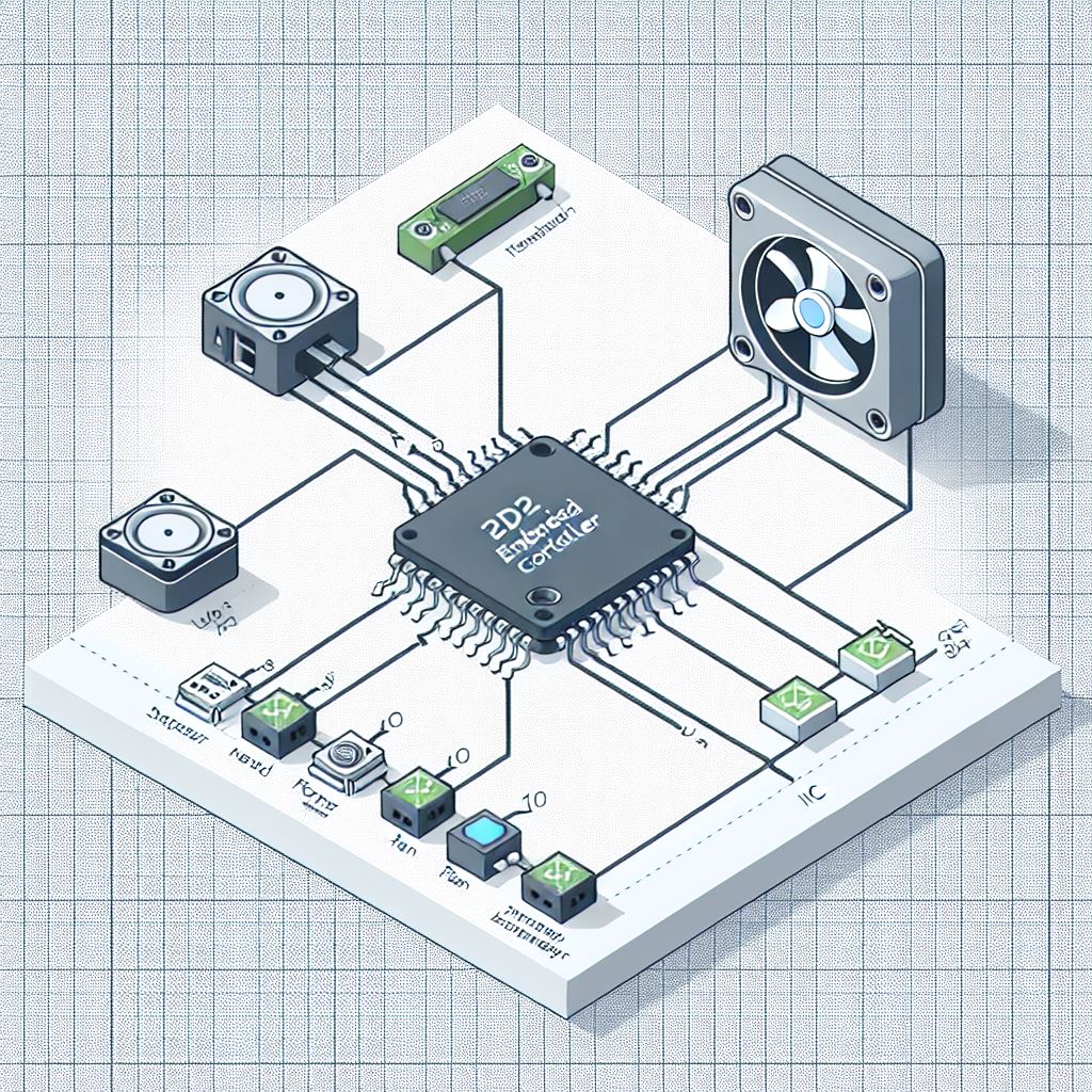
MPTF Drivers
There is 3 primary drivers involved in MPTF
- MPTF Core Driver
- Microsoft Customized IO Driver
- MPTF Customize IO Signal Client
All these drivers are included in OS drops after 26394 as part of the default OS build.
MPTF Core Driver
The Core Driver provides the core logic for MPTF, reads the configuration blob and operates on input and output devices. This driver will not be loaded unless you add the following ACPI entry to load the driver automatically at boot time.
// MPTFCore Driver
Device(MPC0) {
 Name(_HID, "MSFT000D")
 Name (_UID, 1)

}
You can find this driver under windows driverstore folder
C:\Windows\System32\DriverStore\FileRepository\mptfcore.inf_*
If it is enumerated properly you will see it show up as MPTF Core Driver in device manager.

MPTF Core Driver logging can be enable in windbg with the following commands.
!wmitrace.start MptfCore -kd
!wmitrace.enable MptfCore {9BBAB94F-A0B0-4F96-8966-A04F9BA72CA0} -level 0x7 -flag 0xFFFF
Microsoft Customized IO Driver
The Microsoft Customized IO Driver provides a standard interface to the embedded controller to provide input and output values to control fan and thermal properties on the embedded controller.
The ACPI entry for loading the Microsoft Customized IO Driver is as follows
Device(CIO1) {
  Name(_HID, "MSFT000B")
  Name (_UID, 1)
  ...
}
For further details on ACPI definitions and customizations for defining IO inputs and outputs see the section on ACPI.
You can find this driver under windows driverstore folder
C:\Windows\System32\DriverStore\FileRepository\mscustomizedio.inf_*
You will find the driver under device manager in Thermal devices as Microsoft Customized IO Driver
Microsoft Customized IO Driver logging can be enabled in windbg with the following commands.
!wmitrace.start MptfIo -kd
!wmitrace.enable MptfIo {D0ABE2A4-A604-4BEE-8987-55C529C06185} -level 0x7 -flag 0xFFFF
MPTF Custom IO Signal Client Driver
The Custom IO Signal Cient Driver provides ability for OEM's to provide their own custom input and output signals into MPTF. Examples of custom drivers along with input and output definitions can be found in the MPTF specification and are not covered here.
The following ACPI entry will cause the Custom IO Signal Driver to be loaded at boot time.
// MPTF Signal IO Client driver
Device(MPSI) {
  Name(_HID, "MSFT0011")
  Name (_UID, 1)
}
You can find this driver under windows driverstore folder
C:\Windows\System32\DriverStore\FileRepository\mptfcustomizeiosignalclient.inf_*
If it loads with no errors you will see it loaded as MPTF Custom IO Signal Client Driver in device manager.
Microsoft Temperature Sensor Driver
The Temperature Sensor Driver is an input to MPTF that allows MPTF to take actions based on skin temperature or other sensors external to the CPU. Details of the MPTF temperature sensor can be found in the MTPF specification.
The following ACPI entry is necessary to load the Temperature Sensor Driver
// Skin temperature sensor
Device(TMP1) {
  Name(_HID, "MSFT000A")
  Name (_UID, 1)
  ...
The driver is in windows driverstore folder
C:\Windows\System32\DriverStore\FileRepository\mstemperaturesensor.inf_*
If it loads with no failures you should see it listed in device manager
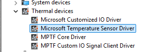
ACPI Entries for MPTF
Windows will boot and run without the MPTF driver loading, however it will not provide any inbox default handling of thermal control.
For any MPTF functionality the Core Driver must be loaded with the following ACPI entry
// MPTFCore Driver
Device(MPC0) {
  Name(_HID, "MSFT000D")
  Name (_UID, 1)
}
There is no requirement to define further resources through the core driver those are all controlled by the IO driver entries.
Microsoft Temperature Sensor Driver
This driver is loaded uner MSFT000A entry, it must always define a _TMP method and _DSM with support for function 0 and function1. If just these two functions are supported function 0 will return 0x3
  Method (_TMP) {
    // Check to make sure FFA is available and not unloaded
    If(LEqual(\_SB.FFA0.AVAL,One)) {
      Name(BUFF, Buffer(24){}) // Create buffer for send/recv data
      CreateByteField(BUFF,0,STAT) // Out – Status for req/rsp
      CreateByteField(BUFF,1,LENG) // In/Out – Bytes in req, updates bytes returned
      CreateField(BUFF,16,128,UUID) // UUID of service
      CreateByteField(BUFF,18, CMDD) // In – First byte of command
      CreateByteField(BUFF,19, TMP1) // In – Thermal Zone Identifier
      CreateField(BUFF,144,32,TMPD) // Out – temperature for TZ

      Store(20, LENG)
      Store(0x1, CMDD) // EC_THM_GET_TMP
      Store(1,TMP1)
      Store(ToUUID("31f56da7-593c-4d72-a4b3-8fc7171ac073"), UUID) // Thermal
      Store(Store(BUFF, \_SB_.FFA0.FFAC), BUFF)

      If(LEqual(STAT,0x0) ) // Check FF-A successful?
      {
        Return (TMPD)
      }
    }
    Return(Zero)
  }

  // Update Thresholds
  Method(STMP, 0x2, Serialized) {
    // Check to make sure FFA is available and not unloaded
    If(LEqual(\_SB.FFA0.AVAL,One)) {
      Name(BUFF, Buffer(32){}) // Create buffer for send/recv data
      CreateByteField(BUFF,0,STAT) // Out – Status for req/rsp
      CreateByteField(BUFF,1,LENG) // In/Out – Bytes in req, updates bytes returned
      CreateField(BUFF,16,128,UUID) // UUID of service
      CreateByteField(BUFF,18, CMDD) // In – First byte of command
      CreateByteField(BUFF,19, TID1) // In – Thermal Zone Identifier
      CreateDwordField(BUFF,20,THS1) // In – Timeout in ms
      CreateDwordField(BUFF,24,THS2) // In – Low threshold tenth Kelvin
      CreateDwordField(BUFF,28,THS3) // In – High threshold tenth Kelvin
      CreateField(BUFF,144,32,THSD) // Out – Status from EC

      Store(0x30, LENG)
      Store(0x2, CMDD) // EC_THM_SET_THRS
      Store(1,TID1)
      Store(0,THS1) // Timout in ms 0 ignore
      Store(Arg0,THS2) // Low Threshold
      Store(Arg1,THS3) // High Threshold
      Store(ToUUID("31f56da7-593c-4d72-a4b3-8fc7171ac073"), UUID) // Thermal
      Store(Store(BUFF, \_SB_.FFA0.FFAC), BUFF)

      If(LEqual(STAT,0x0) ) // Check FF-A successful?
      {
        Return (THSD)
      }
    }
    Return(Zero)
  }


  // Arg0 GUID
  //      1f0849fc-a845-4fcf-865c-4101bf8e8d79 - Temperature GUID
  // Arg1 Revision
  // Arg2 Function Index
  // Arg3 Function dependent
  Method(_DSM, 0x4, Serialized) {
    // Input Variable
    If(LEqual(ToUuid("1f0849fc-a845-4fcf-865c-4101bf8e8d79"),Arg0)) {
        Switch(Arg2) {
          Case(0) {
            // We support function 0,1
            Return (Buffer() {0x03, 0x00, 0x00, 0x00})
          }
          // Update Thresholds
          // Arg3 = Package () { LowTemp, HighTemp }
          Case(1) {
            Return(STMP(DeRefOf(Index(Arg3,0)),DeRefOf(Index(Arg3,1)))) // Set Temp low and high threshold
          }
        }
    }

    Return (Ones)
  }
Microsoft Customized IO Signal Driver
This driver is loaded under MSFT0011 entry, and must always define Function 0 for both input and output devices. Function 0 is a bitmask of all the other variables that are supported on this platform. If you support functions 1,2,3 you would return 0b1111 (0xf) to indicate support for function 0-3.
  // Arg0 GUID
  //      07ff6382-e29a-47c9-ac87-e79dad71dd82 - Input
  //      d9b9b7f3-2a3e-4064-8841-cb13d317669e - Output
  // Arg1 Revision
  // Arg2 Function Index
  // Arg3 Function dependent
  Method(_DSM, 0x4, Serialized) {
    // Input Variable
    If(LEqual(ToUuid("07ff6382-e29a-47c9-ac87-e79dad71dd82"),Arg0)) {
        Switch(Arg2) {
          Case(0) {
            // We support function 0-3
            Return (Buffer() {0x0f, 0x00, 0x00, 0x00})
          }
          Case(1) {
            Return(GVAR(1,ToUuid("db261c77-934b-45e2-9742-256c62badb7a"))) // MinRPM
          }
          Case(2) {
            Return(GVAR(1,ToUuid("5cf839df-8be7-42b9-9ac5-3403ca2c8a6a"))) // MaxRPM
          }
          Case(3) {
            Return(GVAR(1,ToUuid("adf95492-0776-4ffc-84f3-b6c8b5269683"))) // CurrentRPM
          }
        }
        Return(Ones)
    }
    // Output Variable
    If(LEqual(ToUuid("d9b9b7f3-2a3e-4064-8841-cb13d317669e"),Arg0)) {
        Switch(Arg2) {
          Case(0) {
            // We support function 0-3
            Return (Buffer() {0x0f, 0x00, 0x00, 0x00})
          }
          Case(1) {
            Return(SVAR(1,ToUuid("db261c77-934b-45e2-9742-256c62badb7a"),Arg3)) // MinRPM
          }
          Case(2) {
            Return(SVAR(1,ToUuid("5cf839df-8be7-42b9-9ac5-3403ca2c8a6a"),Arg3)) // MaxRPM
          }
          Case(3) {
            Return(SVAR(1,ToUuid("adf95492-0776-4ffc-84f3-b6c8b5269683"),Arg3)) // CurrentRPM
          }
        }
        Return(Ones)
    }

    Return (Ones)
  }
In this case we've assigned the following meanings to supported functions
Function 1 --> MinRPM
Function 2 --> MaxRPM
Function 3 --> CurrentRPM
The meaning of what Function 1 does is mapped by the configuration Blob for your device, so Function 1 need not always be MinRPM. For communication with the EC we've assigned UUID's to each variable we support on the EC. This allows us to keep the same UUID for MinRPM on all platform implementations even though it may be a different function.
The following is the list of UUID's and variables we have defined for our reference implementation, but further mappings can be added by OEM's as well.
| Variable | GUID | Description | OnTemp | ba17b567-c368-48d5-bc6f-a312a41583c1 | Lowest temperature at which the fan is turned on. | RampTemp | 3a62688c-d95b-4d2d-bacc-90d7a5816bcd | Temperature at which the fan starts ramping from min speed. | MaxTemp | dcb758b1-f0fd-4ec7-b2c0-ef1e2a547b76 | Temperature at top of fan ramp where fan is at maximum speed. | CrtTemp | 218246e7-baf6-45f1-aa13-07e4845256b8 | Critical temperature at which we need to shut down the system. | ProcHotTemp | 22dc52d2-fd0b-47ab-95b8-26552f9831a5 | Temperature at which the EC will assert the PROCHOT notification. | MinRpm | db261c77-934b-45e2-9742-256c62badb7a | Minimum RPM FAN speed | MinDba (Optional) | 0457a722-58f4-41ca-b053-c7088fcfb89d | Minimum Dba from FAN | MinSones (Optional) |
311668e2-09aa-416e-a7ce-7b978e7f88be | Minimum Sones from FAN | MaxRpm | 5cf839df-8be7-42b9-9ac5-3403ca2c8a6a | Maximum RPM for FAN | MaxDba (Optional) | 372ae76b-eb64-466d-ae6b-1228397cf374 | Maximum DBA for FAN | MaxSones (Optional) | 6deb7eb1-839a-4482-8757-502ac31b20b7 | Maximum Sones for FAN | ProfileType | 23b4a025-cdfd-4af9-a411-37a24c574615 | Set profile for EC, gaming, quiet, lap, etc | CurrentRpm | adf95492-0776-4ffc-84f3-b6c8b5269683 | The current RPM of FAN | CurrentDba (Optional) | 4bb2ccd9-c7d7-4629-9fd6-1bc46300ee77 | The current Dba from FAN | CurrentSones (Optional) | 7719d686-02af-48a5-8283-20ba6ca2e940 | The current Sones from FAN |
|---|
ACPI communication to EC
MPTF refers to input and output channel values, however these need to be communicated to the EC. Above code refers to GVAR and SVAR to get a variable or set a variable. The following ACPI shows example of how to conver this to an FFA command which is sent to the secure EC service and then communicated to the EC. Further details of how this data is sent to the EC is covered in the EC Service section.
  // Arg0 Instance ID
  // Arg1 UUID of variable
  // Return (Status,Value)
  Method(GVAR,2,Serialized) {
    If(LEqual(\_SB.FFA0.AVAL,One)) {
        Name(BUFF, Buffer(52){})
        CreateField(BUFF, 0, 64, STAT) // Out – Status
        CreateField(BUFF, 64, 64, RCVD) // ReceiverId(only lower 16-bits are used)
        CreateField(BUFF, 128, 128, UUID) // UUID of service
        CreateField(BUFF, 256, 8, CMDD) // Command register
        CreateField(BUFF, 264, 8, INST) // In – Instance ID
        CreateField(BUFF, 272, 16, VLEN) // In – Variable Length in bytes
        CreateField(BUFF, 288, 128, VUID) // In – Variable UUID
        CreateField(BUFF, 264, 64, RVAL) // Out – Variable value

        Store(ToUUID("31f56da7-593c-4d72-a4b3-8fc7171ac073"), UUID)
        Store(0x5, CMDD) // EC_THM_GET_VAR
        Store(Arg0,INST) // Save instance ID
        Store(4,VLEN) // Variable is always DWORD here
        Store(Arg1, VUID)
        Store(Store(BUFF, \_SB_.FFA0.FFAC), BUFF)

        If(LEqual(STAT,0x0) ) // Check FF-A successful?
        {
        Return (RVAL)
        }
      }
      Return (Ones)
    }

  // Arg0 Instance ID
  // Arg1 UUID of variable
  // Return (Status,Value)
  Method(SVAR,3,Serialized) {
    If(LEqual(\_SB_.FFA0.AVAL,One)) {
      Name(BUFF, Buffer(56){})

      CreateField(BUFF, 0, 64, STAT) // Out – Status
      CreateField(BUFF, 64, 64, RCVD) // ReceiverId(only lower 16-bits are used)
      CreateField(BUFF, 128, 128, UUID) // UUID of service
      CreateField(BUFF, 256, 8, CMDD) // Command register
      CreateField(BUFF, 264, 8, INST) // In – Instance ID
      CreateField(BUFF, 272, 16, VLEN) // In – Variable Length in bytes
      CreateField(BUFF, 288, 128, VUID) // In – Variable UUID
      CreateField(BUFF, 416, 32, DVAL) // In – Variable Data
      CreateField(BUFF, 264, 64, RVAL) // Out – Variable value

      Store(ToUUID("31f56da7-593c-4d72-a4b3-8fc7171ac073"), UUID)
      Store(0x6, CMDD) // EC_THM_SET_VAR
      Store(Arg0,INST) // Save instance ID
      Store(4,VLEN) // Variable is always DWORD here
      Store(Arg1, VUID)
      Store(Arg2,DVAL)
      Store(Store(BUFF, \_SB_.FFA0.FFAC), BUFF)
      If(LEqual(STAT,0x0) ) // Check FF-A successful?
      {
        Return (RVAL)
      }
    }
    Return (Ones)
  }
Configuration Blob
The configuration blob data is owned by the OEM and allows custom actions to be taken on output paramters based on input channels and settings.
There are two files used to define configuration of the blob:
- PocSpec.txt - Defines Input and Output GUID's and actions to map input to outputs
- PocIF.txt - For a given GUID maps valid ranges and mapping to ACPI output functions
Both these files live directly under the root folder, but will likely move in the future.
Note: If these files are not present or found the MPTF Core driver will yellow bang.
PocSpec.txt
This file defines UUID's for input and output devices. If using an input or output from the OS you must use the existing UUID definitions found in the MPTF documentation.
In this case the output device is defined in the PocIF.txt but must be unique UUID if you are creating your own output channels.
//
// INPUT
   #macro I_OS_PWR_MODE_MPTF         {8945AB0A-35DD-4BEE-82A5-8138892C280D}_1
//
// OUTPUT
   #macro O_FAN1_ACTIVE_RPM           	{91F589E0-45F0-4C6E-A17D-24FD8E8CBDCE}_730

//
// DEMO-B - OS Power Mode Driven Fan RPM
//		Will monitor the OS PWR MODE and then in a lookup TABLE output a target RPM stored in O_FAN1_ACTIVE_RPM
1,0,0,%A_TABLE%,1,1,1,%I_OS_PWR_MODE_MPTF%,%O_FAN1_ACTIVE_RPM%,4,0,0,1,3,5,7,2,4,6,7,15,25,35,45
The last line monitors the input values selected in the OS from the power mode and maps this to output values for O_FAN1_ACTIVE_RPM. The last 4 values are the output values in this case in percentage for the fan speed 15,25,35,45.
@Douglas to fill in further details on the meaning of these other mapping bits
PocIF.txt
This file maps an output channel to an ACPI function along with default, min and max values
// O_FAN1_ACTIVE_RPM
{91F589E0-45F0-4C6E-A17D-24FD8E8CBDCE}_730,1,60,10,20,2,"\_SB.CIO1"
Here the last two parameters maps this output to function 2 in the _DSM function of _SB.CIO1 device in ACPI.
The value before (20) is the default value set if no value is set by the OS.
Previous two values 60,10 are the maximum and minimum valid values.
@Douglas to provide further details on the spec
Debugging
This section describes the order you should follow when validating the MPTF and log files to capture.
Loading Drivers
The first step is to make sure the MPTF drivers are loaded successfully in device manager.
In device manager expand the Thermal devices tab to make sure see the following three devices listed without any yellow bang.
If you don't see the "Thermal devices" in device manager, you are either missing the ACPI entries or the files are not present in your windows folder. Review the sections on ACPI and the MPTF drivers to make sure all the files are present.
If MPTF Core Driver is present but yellow banged, this is normally because of a failure in parsing the PocIF.txt and PocSpec.txt files in the root folder. Make sure these are present and look valid or try a simpler file. If they are valid collect logs that are listed in the Logging section below and review/share.
If Microsoft Customized IO Driver is present but yellow banged, this is normally an issue with your configuration files and ACPI _DSM definitions for input and output devices. Review your ACPI entries for MSFT0011 and make sure all functions referenced in the PocIF.txt are present and valid in your ACPI tables. For further debug collect logs and see section on ACPI debugging to debug ACPI
If MPTF Custom IO Signal Client River is present but yellow banged, this indicates there is normally a problem in your custom input/output driver component. Enable logging in your driver and make sure it is loaded successfully and no failures. Enable all other logs under logging and review content.
Sometimes drivers will not load correctly if the MPTF service is not running so be sure to make sure in your service manager that MPTF service is running and set to automatically start.
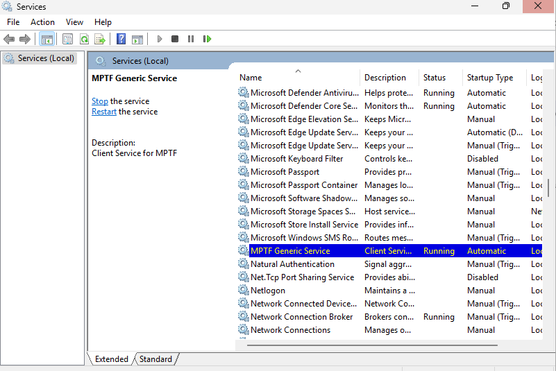
Logging
Logging has moved to EventViewer traces. To view the MPTF events open Event Viewer (eventvwr.msc) and browse to Applications and Services -> Microsoft -> Windows -> MPTF
You will see the MPTF events here for debugging and tracing behaviors.
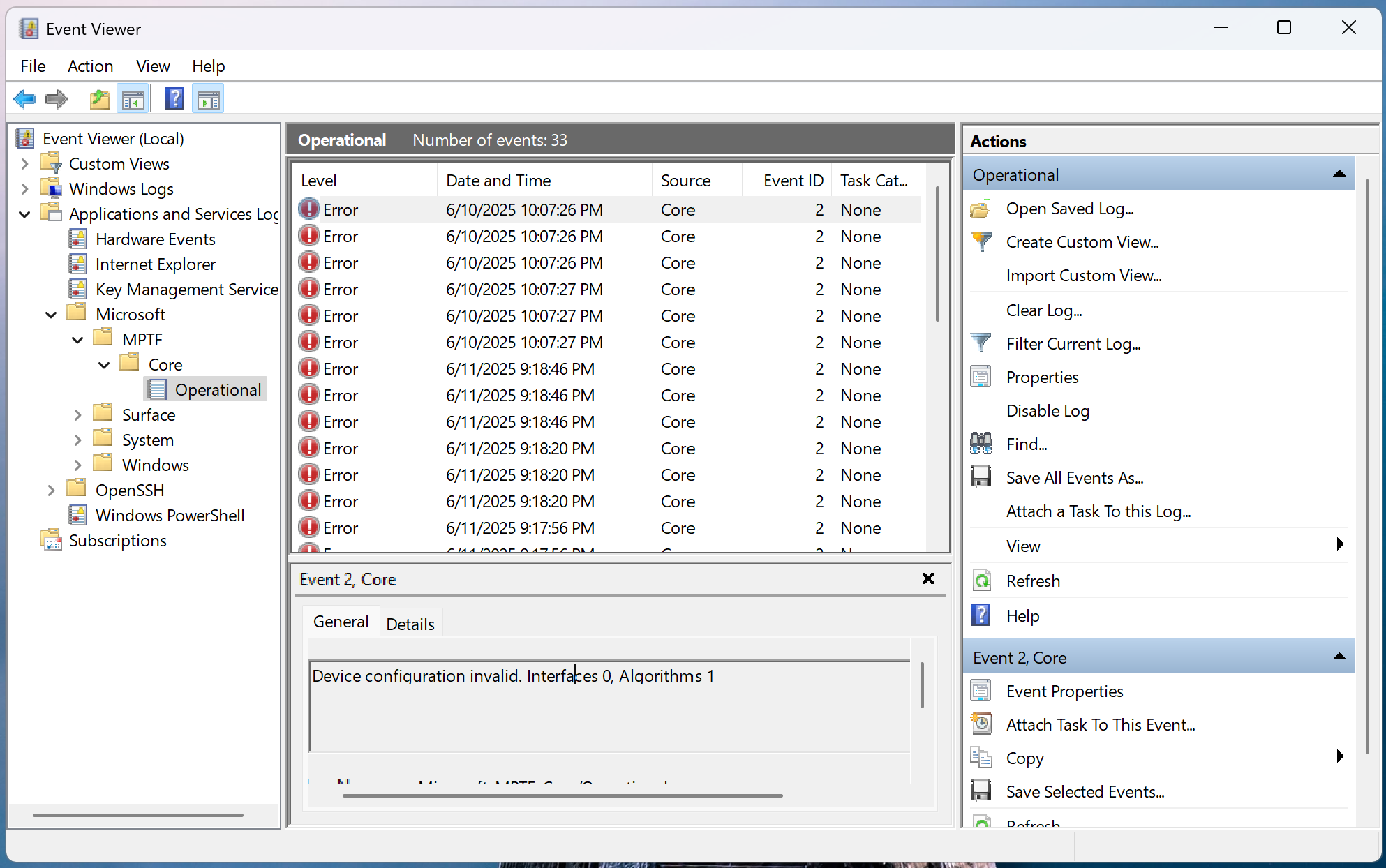
If using secure EC services and sending commands via FFA these logs are captured to the serial port, in this case you should see the output channel value being written to the variable on the serial port logs
15:29:00.621 : SP 8003: DEBUG - set_variable instance id: 0x1
15:29:00.622 : SP 8003:                 length: 0x4
15:29:00.623 : SP 8003:                 uuid: 5cf839df-8be7-42b9-9ac5-3403ca2c8a6a
15:29:00.623 : SP 8003:                 data: 0x19
ACPI Debugging
Since input and output devices go through ACPI calls you may find yourself needing to debug content in ACPI.
!amli set spewon verboseon traceon dbgbrkon
!amli bp \_SB.CIO1._DSM
!amli bl
!amli dns /s \_SB.CIO1
For further details on ACPI debugging see AMLI Debugging
EC Service
On ARM platforms where the interface to the EC is in the secure world, we have a service that runs in the secure world that translates requests from the OS to commands sent to the EC. In the case of MPTF there is a Thermal Service that runs within the EC service to handle requests for custom IO.

ACPI to EC Service Communication
The EC Specification defines commands for get variable and set variable.
EC_THM_GET_VAR = 0x5
EC_THN_SET_VAR = 0x6
Get variable passes in the following structure.
struct GetVar {
    inst: u8,  // Instance of thermal device, there may be multiple fans
    len: u16,  // Length of the variable in this case always 4 bytes
    uuid: uuid, // UUID of the variable see spec
}
This will return status and data
Set variable passes in the following structure
struct SetVar {
    inst: u8,  // Instance of thermal device, there may be multiple fans
    len: u16,  // Length of the variable in this case always 4 bytes
    uuid: uuid, // UUID of the variable see spec
    data: u32, // 32-bit data to write to variable
}
Returns status.
See ACPI section for further details of FFA definition and sending commands. The instance is normally hard coded in ACPI based off the instance definition of ACPI.
EC Service to EC Communication
The communication between the EC service in the secure world and over to the EC MCU itself can vary from platform to platform.
In the example given here the EC is connected via eSPI and we map a chunk of memory in the peripheral channel directly to various variables. The variable maps to an offset in the peripheral channel where the read and write is done for the corresponding entry.
The EC Firmware is notified when a region of memory is updated and will adjust fan and hardware logic based on these new values.
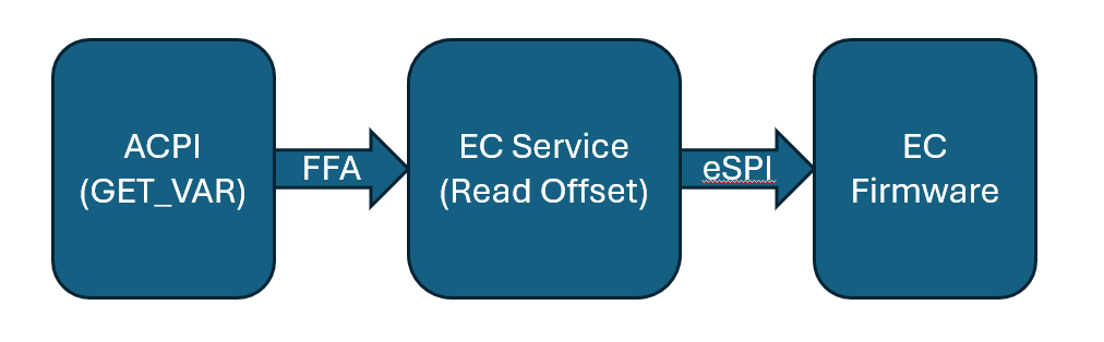
The EC service receives the get/set variable requests in the thermal service
haf-ec-service/ec-service-lib/src/services/thermal/mod.rs
            EC_THM_GET_VAR => {
                rsp.struct_to_args64(&self.get_variable(msg));
                Ok(rsp)
            }
            EC_THM_SET_VAR => {
                rsp.struct_to_args64(&self.set_variable(msg));
                Ok(rsp)
            }
From here it converts it to eSPI peripheral reads and writes.
EC Service ACPI
Sometimes the GVAR and SVAR from CIO may directly map to memory mapped OpRegion in an EC controller such as on Intel platforms. In the case where EC service is present in the secure world on ARM platforms we need to setup a bit more content.
All the communication between non-secure side (NTOS) and secure side (EC Secure Partition) is done through a standard called FF-A.
FFA ACPI Defintion
Make sure in your system in ACPI you have FFA device defined and corresponding _DSD and _DSM methods according to FFA documentation.
Device(\_SB_.FFA0) {
  Name(_HID, "MSFT000C")

  OperationRegion(AFFH, FFixedHw, 2, 144)
  Field(AFFH, BufferAcc, NoLock, Preserve) { AccessAs(BufferAcc, 0x1), FFAC, 1152 }
  ...
  Method(AVAL,0x0, Serialized)
  {
    Return(One)
  }
This should also implment the AVAL function to determine that FFA is loaded and can be used by other ACPI references. If you directly reference FFA0 without checking this if the FFA driver is not loaded can lead to deadlock and other OS issues.
Making FFA Calls
As previously documented in the MPTF section, in the SVAR and GVAR we make calls into FFA. This section documents those parameters in more detail.
    If(LEqual(\_SB.FFA0.AVAL,One)) {        // First check to make sure FFA0 device is available
        Name(BUFF, Buffer(52){})            // Allocate a buffer large enough for all input and output data
        CreateField(BUFF, 0, 64, STAT)      // All FFA commands must have 64-bits status returned
        CreateField(BUFF, 64, 64, RCVD)     // ReceiverId left as zero is populated by the framework
        CreateField(BUFF, 128, 128, UUID)   // UUID of service we want to talk to in this case Thermal Service
        CreateField(BUFF, 256, 8, CMDD)     // Command to send to this service
        CreateField(BUFF, 264, 8, INST)     // Remaining entries are command specific input and output structure definition
        CreateField(BUFF, 272, 16, VLEN)
        CreateField(BUFF, 288, 128, VUID)
        CreateField(BUFF, 264, 64, RVAL)    // Output structure will overlap with input data

        Store(ToUUID("31f56da7-593c-4d72-a4b3-8fc7171ac073"), UUID) // Populate the Thermal Service UUID
        Store(0x5, CMDD)                    // Write command EC_THM_GET_VAR into buffer
        Store(Arg0,INST)                    // Save instance ID into buffer
        Store(4,VLEN)                       // Variable is always DWORD here
        Store(Arg1, VUID)                   // Variable UUID

        Store(Store(BUFF, \_SB_.FFA0.FFAC), BUFF) // Writes BUFF to FFA operation region this actually sends FFA request and gets response

        If(LEqual(STAT,0x0) )               // Check FF-A successful?
        {
            Return (RVAL)                   // Return data in the out buffer
        }
      }
      // Otherwise return an error
For MPTF we mostly just need Get/Set varaible commands and notifications.
EC Notifications
The EC can also send notifications back to the OS if certain events occur. All the notifications come initially through the FFA0 device. When device is defined in ACPI you must list all the logical notification events you expect and the handler for notifications.
Name(_DSD, Package() {
      ToUUID("daffd814-6eba-4d8c-8a91-bc9bbf4aa301"), //Device Prop UUID
      Package() {
        Package(2) {
          "arm-arml0002-ffa-ntf-bind",
          Package() {
              1, // Revision
              1, // Count of following packages
              Package () {
                     ToUUID("31f56da7-593c-4d72-a4b3-8fc7171ac073"), // UUID for thermal
                     Package () {
                          0x01,     // EC_THM_HOT
                          0x02,     // EC_THM_LOW crossed low threshold
                          0x03,     // EC_THM_HIGH crossed high threshold
                      }
              }
         }
      }
    }
  }) // _DSD()

  Method(_DSM, 0x4, NotSerialized)
  {
    // Arg0 - UUID
    // Arg1 - Revision
    // Arg2: Function Index
    //         0 - Query
    //         1 - Notify
    //         2 - binding failure
    //         3 - infra failure
    // Arg3 - Data

    //
    // Device specific method used to query
    // configuration data. See ACPI 5.0 specification
    // for further details.
    //
    If(LEqual(Arg0, Buffer(0x10) {
        //
        // UUID: {7681541E-8827-4239-8D9D-36BE7FE12542}
        //
        0x1e, 0x54, 0x81, 0x76, 0x27, 0x88, 0x39, 0x42, 0x8d, 0x9d, 0x36, 0xbe, 0x7f, 0xe1, 0x25, 0x42
      }))
    {
      // Query Function
      If(LEqual(Arg2, Zero))
      {
        Return(Buffer(One) { 0x03 }) // Bitmask Query + Notify
      }

      // Notify Function
      If(LEqual(Arg2, One))
      {
        // Arg3 - Package {UUID, Cookie}
        Local0 = DeRefOf(Index(Arg3,1))
        Store(Local0,\_SB.ECT0.NEVT )

        Switch(Local0) {
          Case(1) {
            // Handle HOT notification
          }
          Case(2) {
            // Handle Low temp notification
          }
          Case(3) {
            // Handle High temp notification
          }
        }
      }
    } Else {
      Return(Buffer(One) { 0x00 })
    }
  }
EC Service Debugging
Since the EC service runs in the secure world you cannot debug it through windbg. Most debugging is done through serial log messages or JTAG with SWD.
For SWD debugging see references to Hafnium and JTAG debugging.
Serial Debug
In the code you can simply use println or logging interface and these messages will be routed to serial port by default.
Eg.
        println!(
            "set_variable instance id: 0x{:x}
                length: 0x{:x}
                uuid: {}
                data: 0x{:x}",
            req.id, req.len, req.var_uuid, req.data
        );
You will see these messages printed out on the serial terminal
15:29:00.621 : SP 8003: DEBUG - set_variable instance id: 0x1
15:29:00.622 : SP 8003:                 length: 0x4
15:29:00.623 : SP 8003:                 uuid: 5cf839df-8be7-42b9-9ac5-3403ca2c8a6a
15:29:00.623 : SP 8003:                 data: 0x19
MCU Firmware
The MCU Firmware has a region of 256 bytes that is mapped as the peripheral channel on eSPI. This is used to read and write 32-bit values to and from the EC. Based on the parameters that we read and write the MCU firmware will adjust fan speeds and other parameters within the EC that adjust thermal.
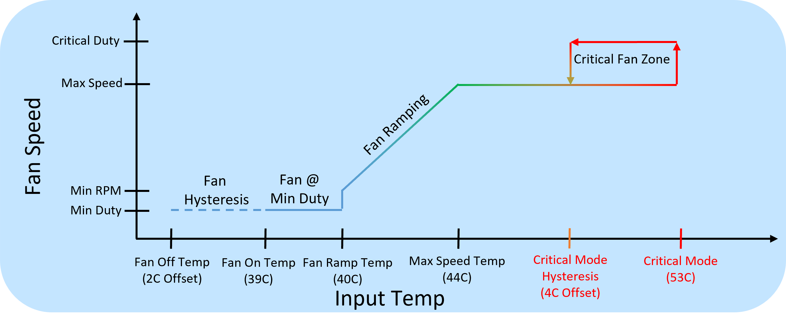
Apps to MCU Interface
When using eSPI transport we define a mapped memory region in the peripheral bus, that must be agreed on between apps side and MCU side.
Memory Layout Definition
Both apps side and MCU side are using RUST, we define the memory layout in YAML format and currently have a python script that converts this to a RUST format.
embedded-services/embedded-service/src/ec_type/generator/ec_memory.yaml
# EC Memory layout definition

Version:
  major:
    type: u8
  minor:
    type: u8
  spin:
    type: u8
  res0:
    type: u8
...
# Size 0x38
Thermal:
  events:
    type: u32
  cool_mode:
    type: u32
  dba_limit:
    type: u32
  sonne_limit:
    type: u32
  ma_limit:
    type: u32
  fan1_on_temp:
    type: u32
  fan1_ramp_temp:
    type: u32
  fan1_max_temp:
    type: u32
  fan1_crt_temp:
    type: u32
  fan1_hot_temp:
    type: u32
  fan1_max_rpm:
    type: u32
  fan1_cur_rpm:
    type: u32
  tmp1_val:
    type: u32
  tmp1_timeout:
    type: u32
  tmp1_low:
    type: u32
  tmp1_high:
    type: u32
Converting YAML to RUST
To convert YAML to RUST simply run the ec-memory-generator.py using the following command
python ec-memory-generator.py ec_memory.yaml
This will outut the following two files for C based structure definition and RUST based
structure.rs
ecmemory.h
When compiling embedded-services the structure.rs must be copied under
embedded-services/embedded-service/src/ec_type
Versioning
Any time a breaking change is made the major version must be updated and if EC and apps don't agree on a major version the fields cannot be interpreted. Whenever possible we only want to add fields which means we can keep the structure backwards compatible and just the minor version can be updated.
MCU eSPI Service
When the apps modifies or writes some value into the peripheral channel on the MCU side a service can register for notifications to specific regions of the memory map. The handling of all eSPI events can be found in
embedded-services/espi-service/src/espi_service.rs
This contains the entry point and main message handling loop.
#[embassy_executor::task]
pub async fn espi_service(mut espi: espi::Espi<'static>, memory_map_buffer: &'static mut [u8]) {
    info!("Reserved eSPI memory map buffer size: {}", memory_map_buffer.len());
    info!("eSPI MemoryMap size: {}", size_of::<ec_type::structure::ECMemory>());
    ...
    loop {
        ...
    }
VWire events and Peripheral channel events come in on Port 0, while OOB messages come in on Port 1. For details about the eSPI protocol see the eSPI secification
Based on the offset of the access in the peripheral channel the data is routed to the correct service
    if offset >= offset_of!(ec_type::structure::ECMemory, therm)
                && offset < offset_of!(ec_type::structure::ECMemory, therm) + size_of::<ec_type::structure::Thermal>()
    {
        self.route_to_thermal_service(&mut offset, &mut length).await?;
    }
This gets converted to a transport independent message and routed to the thermal endpoint that can register and listen for these messages
    async fn route_to_thermal_service(&self, offset: &mut usize, length: &mut usize) -> Result<(), ec_type::Error> {
        let msg = {
            let memory_map = self.ec_memory.borrow();
            ec_type::mem_map_to_thermal_msg(&memory_map, offset, length)?
        };

        comms::send(
            EndpointID::External(External::Host),
            EndpointID::Internal(Internal::Thermal),
            &msg,
        )
        .await
        .unwrap();

        Ok(())
    }
    ```
MCU Debugging
Debugging on the MCU side is done primarily with J-Link SWD connection. Some platforms will provide a dedicated serial port to the MCU that allows debug print messages.
J-Link Debugging
With JTAG debugger you can set breakpoints and step through MCU side code as well as print messages out through the JTAG port using probe-rs.
    info!("Reserved eSPI memory map buffer size: {}", memory_map_buffer.len());
    info!("eSPI MemoryMap size: {}", size_of::<ec_type::structure::ECMemory>());
@Jerry and Felipe to provide further details or link to MCU debugging document
MPTF Demo
Prerequisites
You will need a hardware platform that has the following:
- Boots OS 26400 or later with MPTF support
- ACPI changes for Custom IO and MPTF driver loading
- haf-ec-service with eSPI or other transport from ODP
- MCU firmware code that runs on your MCU from ODP
MPTF and Customized IO
After booting the device copy both the following PocIF.txt and PocSpec.txt to root folder on the device
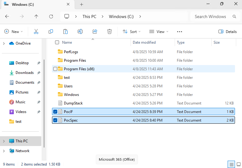
After copying these files we reboot the computer and check in device manager to make sure MPTF devices are all running with no failures.
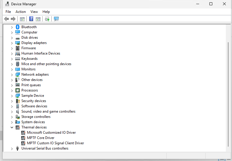
Open System Settings and select Power
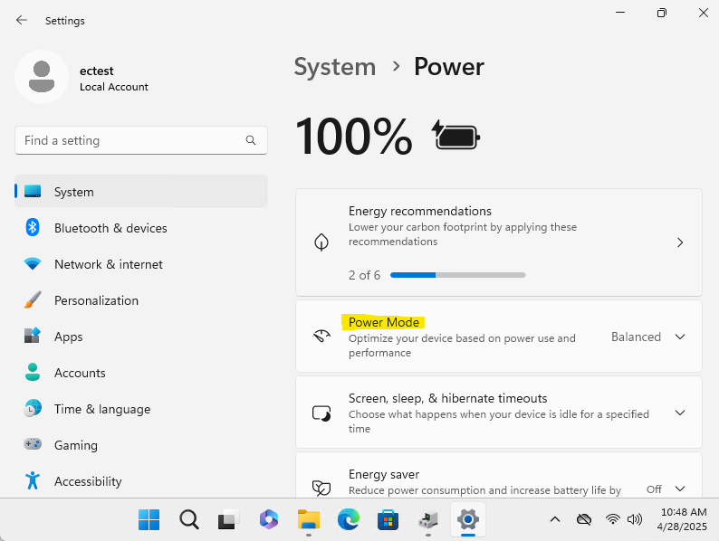
With windbg connecteded and logging enabled for Microsoft Custom IO driver when we change the power mode we will see values being selected.
!wmitrace.stop MptfIo -kd
!wmitrace.start MptfIo -kd
!wmitrace.enable MptfIo {D0ABE2A4-A604-4BEE-8987-55C529C06185} -level 0x7 -flag 0xFFFF
!wmitrace.dynamicprint 1
.reload /f
As you select the different values for Balanced, Best Performance etc you will see it executing the Customized IO functions with the corresponding values defined form the PocSpec.
[1]0004.03A4::04/28/2025-10:58:28.051 [kernel] [SmfInterface_RequestCompletionHandling]Deferred execution: Data write activated
[1]0004.03A4::04/28/2025-10:58:28.067 [mptfcustomizeiosignalclient] [MptfInterfaceDataSet]MptfInterfaceDataSet Received data on channel:0 with value:35 FunctionId 2.
[3]0004.03A4::04/28/2025-10:58:30.211 [kernel] [SmfInterface_RequestCompletionHandling]Deferred execution: Data write activated
[3]0004.03A4::04/28/2025-10:58:30.243 [mptfcustomizeiosignalclient] [MptfInterfaceDataSet]MptfInterfaceDataSet Received data on channel:0 with value:25 FunctionId 2.
[1]0004.03A4::04/28/2025-10:58:32.387 [kernel] [SmfInterface_RequestCompletionHandling]Deferred execution: Data write activated
[1]0004.03A4::04/28/2025-10:58:32.403 [mptfcustomizeiosignalclient] [MptfInterfaceDataSet]MptfInterfaceDataSet Received data on channel:0 with value:15 FunctionId 2.
Hafnium EC Service
Now we demonstrate that the data is received and requests are processed in secure world side. Connecting terminal to our debug serial port we can get the Hanfnium debug messages for each of these power modes we select.
We see that it calls set_variable for instance id: 0x1 with the variable UUID we specify in our ACPI the the value select from the UI
11:02:10.823 : SP 8003: DEBUG - Successfully received ffa msg:
11:02:10.824 : SP 8003: function_id = c400008d
11:02:10.824 : SP 8003: uuid = 31f56da7-593c-4d72-a4b3-8fc7171ac073
11:02:10.824 : SP 8003: DEBUG - Received ThmMgmt command 0x6
11:02:10.824 : SP 8003: DEBUG - set_variable instance id: 0x1
11:02:10.824 : SP 8003: length: 0x4
11:02:10.824 : SP 8003: uuid: 5cf839df-8be7-42b9-9ac5-3403ca2c8a6a
11:02:10.824 : SP 8003: data: 0x23
11:02:12.647 : SP 8003: DEBUG - Successfully received ffa msg:
11:02:12.647 : SP 8003: function_id = c400008d
11:02:12.648 : SP 8003: uuid = 31f56da7-593c-4d72-a4b3-8fc7171ac073
11:02:12.648 : SP 8003: DEBUG - Received ThmMgmt command 0x6
11:02:12.648 : SP 8003: DEBUG - set_variable instance id: 0x1
11:02:12.648 : SP 8003: length: 0x4
11:02:12.648 : SP 8003: uuid: 5cf839df-8be7-42b9-9ac5-3403ca2c8a6a
11:02:12.648 : SP 8003: data: 0x19
11:02:14.199 : SP 8003: DEBUG - Successfully received ffa msg:
11:02:14.199 : SP 8003: function_id = c400008d
11:02:14.200 : SP 8003: uuid = 31f56da7-593c-4d72-a4b3-8fc7171ac073
11:02:14.200 : SP 8003: DEBUG - Received ThmMgmt command 0x6
11:02:14.200 : SP 8003: DEBUG - set_variable instance id: 0x1
11:02:14.200 : SP 8003: length: 0x4
11:02:14.200 : SP 8003: uuid: 5cf839df-8be7-42b9-9ac5-3403ca2c8a6a
11:02:14.200 : SP 8003: data: 0xf
EC MCU Functionality
Finally we validate that the uCode running on the MCU actually receives this data and takes the correct corresponding action. In this example we directly map this variable to the fan RPM as a percentage. As you change the setting in the UI and see the commands in Hafnium EC Service changing values in peripheral channel on the MCU side we receive those notfications and set the fan speed accordingly
Add debug output from MCU here as well.
The Thermal Component Example
In this example we will be constructing a functioning mock thermal component subsystem.
TODO -- this will closely follow the pattern of the Battery example
Goals
The thermal itself will be virtual - no hardware required - and the behavioral aspects of it will be simulated. We will, however, discuss what one would do to implement actual thermal hardware control in a HAL layer.
In this example, we will:
- Define the Traits of the thermal component
- Identify the hardware actions that fulfill these traits
- Define the HAL traits to match these hardware actions
- Implement the HAL traits to hardware access (or define mocks for a virtual example)
- Wrap this simple Traits implementation into a Device for service insertion
- Provide the service layer and insert the device into it
- Test the end result with unit tests and simple executions
- Update the project for an embedded build and deploy onto hardware.
How we will build the Thermal Component
TODO: This will mirror the similar steps for Battery
Thermal component Diagrams
TODO: This will mirror similar content for Battery
The construction of a component such as our thermal subsystem looks as follows.
flowchart TD
A[Service<br><i>Service initiates query</i>]
B[Thermal Subsystem Controller<br><i>Orchestrates component behavior</i>]
C[Thermal Component Trait Interface<br><i>Defines the functional contract</i>]
D[Thermal HAL Implementation<br><i>Implements trait using hardware-specific logic</i>]
E[EC / Hardware Access<br><i>Performs actual I/O operations</i>]
A --> B
B --> C
C --> D
D --> E
subgraph Service Layer
A
end
subgraph Subsystem Layer
B
end
subgraph Component Layer
C
D
end
subgraph Hardware Layer
E
end
When in operation, it conducts its operations in response to message events
TODO: Will be similar to battery example diagram
Building the component
TODO: Will be similar to Battery content for this section
A Mock Thermal Subsystem Project
TODO: Will be similar to Battery content for this section
Using the ODP repositories for defined Thermal traits
TODO: Will be similar to Battery content for this section
Thermal values
TODO: Will be similar to Battery content for this section
Thermal Service Preparation
TODO: Will be similar to Battery content for this section
Thermal Service Registry
TODO: Will be similar to Battery content for this section
Unit Tests
TODO: Will be similar to Battery content for this section
Integration
Embedded Targeting
Project Board
Dependencies
Code Changes
Logging
Flashing
Testing
Integrating the Virtual Laptop
TODO This section will take the components created in the previous exercises and apply them in an integration that covers
-
setting up QEMU as a host
-
communicate with the EC we have constructed in exercises
-
run some tests
Summary and Takeaways
ODP Specification documents
Adherence to the specifications defined by the ODP allow for component portability and auditing.
Embedded Controller Interface Specification
Embedded Controller(EC) Interface Specification describes base set of requirements to interface to core windows features. It covers the following areas:
- Firmware Management
- Battery
- Time and Alarm
- UCSI
- Thermal and Power
- Input Devices
- Customization
EC SOC Interface
EC Physical Interface
The interface by which the EC is physically wired to the SOC may vary depending on what interfaces are supported by the Silicon Vendor, EC manufacturer and OEM. It is recommended that a simple and low latency protocol is chosen such as eSPI, I3C, UART, memory.
EC Software Interface
There are several existing OS interfaces that exist today via ACPI and HID to manage thermal, battery, keyboard, touch etc. These existing structures need to keep working and any new interface must be created in such a way that it does not break existing interfaces. This document covers details on how to implement EC services in secure world and keep compatibility with non-secure EC OperationRegions. It is important to work towards a more robust solution that will handle routing, larger packets and security in a common way across OS’s and across SV architectures.
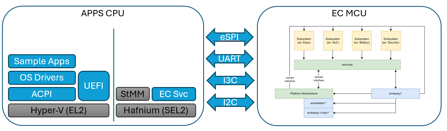
Legacy EC Interface
ACPI specification has a definition for an embedded controller, however this implementation is tied very closely to the eSPI bus and x86 architecture.
The following is an example of legacy EC interface definition from ACPI
11.7. Thermal Zone Examples — ACPI Specification 6.4 documentation
Scope(\\_SB.PCI0.ISA0) {
Device(EC0) {
Name(_HID, EISAID("PNP0C09")) // ID for this EC
// current resource description for this EC
Name(_CRS, ResourceTemplate() {
IO(Decode16,0x62,0x62,0,1)
IO(Decode16,0x66,0x66,0,1)
})
Name(_GPE, 0) // GPE index for this EC
// create EC's region and field for thermal support
OperationRegion(EC0, EmbeddedControl, 0, 0xFF)
Field(EC0, ByteAcc, Lock, Preserve) {
MODE, 1, // thermal policy (quiet/perform)
FAN, 1, // fan power (on/off)
, 6, // reserved
TMP, 16, // current temp
AC0, 16, // active cooling temp (fan high)
, 16, // reserved
PSV, 16, // passive cooling temp
HOT 16, // critical S4 temp
CRT, 16 // critical temp
}
// following is a method that OSPM will schedule after
// it receives an SCI and queries the EC to receive value 7
Method(_Q07) {
Notify (\\_SB.PCI0.ISA0.EC0.TZ0, 0x80)
} // end of Notify method
// fan cooling on/off - engaged at AC0 temp
PowerResource(PFAN, 0, 0) {
Method(_STA) { Return (\\_SB.PCI0.ISA0.EC0.FAN) } // check power state
Method(_ON) { Store (One, \\\\_SB.PCI0.ISA0.EC0.FAN) } // turn on fan
Method(_OFF) { Store ( Zero, \\\\_SB.PCI0.ISA0.EC0.FAN) }// turn off
fan
}
// Create FAN device object
Device (FAN) {
// Device ID for the FAN
Name(_HID, EISAID("PNP0C0B"))
// list power resource for the fan
Name(_PR0, Package(){PFAN})
}
// create a thermal zone
ThermalZone (TZ0) {
Method(_TMP) { Return (\\_SB.PCI0.ISA0.EC0.TMP )} // get current temp
Method(_AC0) { Return (\\_SB.PCI0.ISA0.EC0.AC0) } // fan high temp
Name(_AL0, Package(){\\_SB.PCI0.ISA0.EC0.FAN}) // fan is act cool dev
Method(_PSV) { Return (\\_SB.PCI0.ISA0.EC0.PSV) } // passive cooling
temp
Name(_PSL, Package (){\\_SB.CPU0}) // passive cooling devices
Method(_HOT) { Return (\\_SB.PCI0.ISA0.EC0.HOT) } // get critical S4
temp
Method(_CRT) { Return (\\_SB.PCI0.ISA0.EC0.CRT) } // get critical temp
Method(_SCP, 1) { Store (Arg1, \\\\_SB.PCI0.ISA0.EC0.MODE) } // set
cooling mode
Name(_TSP, 150) // passive sampling = 15 sec
Name(_TZP, 0) // polling not required
Name (_STR, Unicode ("System thermal zone"))
} // end of TZ0
} // end of ECO
} // end of \\\\_SB.PCI0.ISA0 scope-
On platforms that do not support IO port access there is an option to define MMIO regions to simulate the IO port transactions.
In the above example you can see that the operation region directly maps to features on the EC and you can change the EC behavior by writing to a byte in the region or reading the latest data from the EC.
For a system with the EC connected via eSPI and that needs a simple non-secure interface to the EC the above mapping works very well and keeps the code simple. The eSPI protocol itself has details on port accesses and uses the peripheral channel to easily read/write memory mapped regions.
As the EC features evolve there are several requirements that do no work well with this interface:
-
Different buses such as I3C, SPI, UART target a packet request/response rather than a memory mapped interface
-
Protected or restricted access and validation of request/response
-
Firmware update, large data driven requests that require larger data response the 256-byte region is limited
-
Discoverability of features available and OEM customizations
-
Out of order completion of requests, concurrency, routing and priority handling
As we try to address these limitations and move to a more packet based protocol described in this document. The following section covers details on how to adopt existing operation region to new ACPI functionality.
Adopting EC Operation Region
The new OS frameworks such as MPTF still use ACPI methods as primary interface. Instead of defining devices such as FAN or ThermalZone in the EC region you can simply define the EC region itself and then map all the other ACPI functions to operate on this region. This will allow you to maintain backwards compatibility with existing EC definitions.
Device(EC0) {
Name(_HID, EISAID("PNP0C09")) // ID for this EC
// current resource description for this EC
Name(_CRS, ResourceTemplate() {
IO(Decode16,0x62,0x62,0,1)
IO(Decode16,0x66,0x66,0,1)
})
// create EC's region and field for thermal support
OperationRegion(EC0, EmbeddedControl, 0, 0xFF)
Field(EC0, ByteAcc, Lock, Preserve) {
MODE, 1, // thermal policy (quiet/perform)
FAN, 1, // fan power (on/off)
, 6, // reserved
TMP, 16, // current temp
AC0, 16, // active cooling temp (fan high)
, 16, // reserved
PSV, 16, // passive cooling temp
HOT 16, // critical S4 temp
CRT, 16 // critical temp
}
}
Device(SKIN) {
Name(_HID, "MSFT000A") // New MPTF HID Temperature Device
Method(_TMP, 0x0, Serialized) {
Return( \\_SB.PCI0.ISA0.EC0.TMP)
}
}
For more complicated functions that take a package some of the data may be constructed within ACPI and some of the data pulled from the OperationRegion. For example BIX for battery information may have a combination of static and dynamic data like this:
Method (_BIX) {
Name (BAT0, Package (0x12)
{
0x01, // Revision
0x02, // Power Unit
0x03, // Design Capacity
\\_SB.PCI0.ISA0.EC0.BFCC, // Last Full Charge Capacity
0x05, // Battery Technology
0x06, // Design Voltage
0x07, // Design capacity of Warning
0x08, // Design Capacity of Low
\\_SB.PCI0.ISA0.EC0.BCYL, // Cycle Count
0x0A, // Measurement Accuracy
0x0B, // Max Sampling Time
0x0C, // Min Sampling Time
0x0D, // Max Averaging Interval
0x0E, // Min Averaging Interval
0x0F, // Battery Capacity Granularity 1
0x10, // Battery Capacity Granularity 2
"Model123", // Model Number
"Serial456", // Serial Number
"Li-Ion", // Battery Type
"OEMName" // OEM Information
})
Return(BAT0)
}
Limitations for using Legacy EC
Before using the Legacy EC definition OEM’s should be aware of several use cases that may limit you ability to use it.
ACPI support for eSPI master
In the case of Legacy EC the communication to the EC is accomplished directly by the ACPI driver using PORT IO and eSPI Peripheral Bus commands. On ARM platforms there is no PORT IO and these must be substituted with MMIO regions. The ACPI driver needs changes to support MMIO which is being evaluated and support is not yet available. Some Silicon Vendors also do not implement the full eSPI specification and as such the ACPI driver cannot handle all the communication needs. On these platforms using Legacy EC interface is not an option.
Security of eSPI bus
When non-secure world is given access to the eSPI bus it can send commands to device on that bus. Some HW designs have the TPM or SPINOR on the same physical bus as the EC. On these designs allowing non-secure world to directly sends commands to EC can break the security requirements of other devices on the bus. In these cases the eSPI communication must be done in the secure world over FF-A as covered in this document and not use the Legacy EC channel. Since non-secure world has complete access to the EC operation region there is no chance for encryption of data. All data in the operation region is considered non-secure.
Functional limitations of Legacy EC
The peripheral region that is mapped in the Legacy EC in ACPI is limited to 256 bytes and notification events to the ones that are defined and handled in ACPI driver. To create custom solutions, send large packets or support encryption of data the Legacy EC interface has limitations in this area.
Secure EC Services Overview
In this section we review a system design where the EC communication is in the secure world running in a dedicated SP. In a system without secure world or where communication to EC is not desired to be secure all the ACPI functions can be mapped directly to data from the EC operation region.
The following github projects provide sample implementations of this interface:
ACPI EC samples, Kernel mode test driver, User mode test driver
Sample Secure Partition Service for EC services in RUST
RUST crate for FFA implementation in secure partition
The following GUID’s have been designed to represent each service operating in the secure partition for EC.
| EC Service Name | Service GUID | Description |
|---|---|---|
| EC_SVC_MANAGEMENT | 330c1273-fde5-4757-9819-5b6539037502 | Used to query EC functionality, Board info, version, security state, FW update |
| EC_SVC_POWER | 7157addf-2fbe-4c63-ae95-efac16e3b01c | Handles general power related requests and OS Sx state transition state notification |
| EC_SVC_BATTERY | 25cb5207-ac36-427d-aaef-3aa78877d27e | Handles battery info, status, charging |
| EC_SVC_THERMAL | 31f56da7-593c-4d72-a4b3-8fc7171ac073 | Handles thermal requests for skin and other thermal events |
| EC_SVC_UCSI | 65467f50-827f-4e4f-8770-dbf4c3f77f45 | Handles PD notifications and calls to UCSI interface |
| EC_SVC_INPUT | e3168a99-4a57-4a2b-8c5e-11bcfec73406 | Handles wake events, power key, lid, input devices (HID separate instance) |
| EC_SVC_TIME_ALARM | 23ea63ed-b593-46ea-b027-8924df88e92f | Handles RTC and wake timers. |
| EC_SVC_DEBUG | 0bd66c7c-a288-48a6-afc8-e2200c03eb62 | Used for telemetry, debug control, recovery modes, logs, etc |
| EC_SVC_TEST | 6c44c879-d0bc-41d3-bef6-60432182dfe6 | Used to send commands for manufacturing/factory test |
| EC_SVC_OEM1 | 9a8a1e88-a880-447c-830d-6d764e9172bb | Sample OEM custom service and example piping of events |
FFA Overview
This section covers the components involved in sending a command to EC through the FFA flow in windows. This path is specific to ARM devices and a common solution with x64 is still being worked out. Those will continue through the non-secure OperationRegion in the near term.
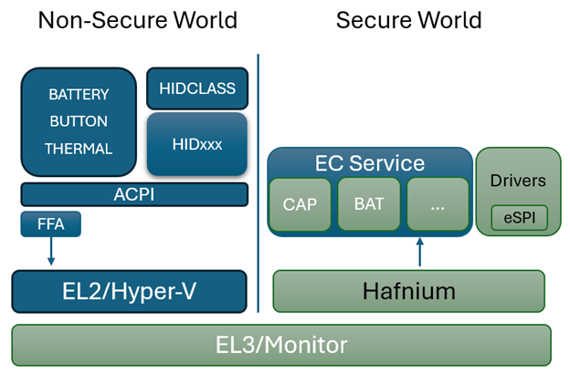
ARM has a standard for calling into the secure world through SMC’s and targeting a particular service running in secure world via a UUID. The full specification and details can be found here: Firmware Framework for A-Profile
The windows kernel provides native ability for ACPI to directly send and receive FFA commands. It also provides a driver ffadrv.sys to expose a DDI that allows other drivers to directly send/receive FFA commands without needing to go through ACPI.
Hyper-V forwards the SMC’s through to EL3 to Hafnium which then uses the UUID to route the request to the correct SP and service. From the corresponding EC service it then calls into the eSPI or underlying transport layer to send and receive the request to the physical EC.
FFA Device Definition
The FFA device is loaded from ACPI during boot and as such requires a Device entry in ACPI
Name(_HID, "ARML0002")
OperationRegion(AFFH, FFixedHw, 2, 144)
Field(AFFH, BufferAcc, NoLock, Preserve) { AccessAs(BufferAcc, 0x1), FFAC, 1152 }
Name(_DSD, Package() {
ToUUID("daffd814-6eba-4d8c-8a91-bc9bbf4aa301"), //Device Prop UUID
Package() {
Package(2) {
"arm-arml0002-ffa-ntf-bind",
Package() {
1, // Revision
2, // Count of following packages
Package () {
ToUUID("330c1273-fde5-4757-9819-5b6539037502"), // Service1 UUID
Package () {
0x01, //Cookie1 (UINT32)
0x07, //Cookie2
}
},
Package () {
ToUUID("b510b3a3-59f6-4054-ba7a-ff2eb1eac765"), // Service2 UUID
Package () {
0x01, //Cookie1
0x03, //Cookie2
}
}
}
}
}
}) // _DSD()
Method(_DSM, 0x4, NotSerialized)
{
// Arg0 - UUID
// Arg1 - Revision
// Arg2: Function Index
// 0 - Query
// 1 - Notify
// 2 - binding failure
// 3 - infra failure
// Arg3 - Data
//
// Device specific method used to query
// configuration data. See ACPI 5.0 specification
// for further details.
//
If(LEqual(Arg0, Buffer(0x10) {
//
// UUID: {7681541E-8827-4239-8D9D-36BE7FE12542}
//
0x1e, 0x54, 0x81, 0x76, 0x27, 0x88, 0x39, 0x42, 0x8d, 0x9d, 0x36, 0xbe, 0x7f, 0xe1, 0x25, 0x42
}))
{
// Query Function
If(LEqual(Arg2, Zero))
{
Return(Buffer(One) { 0x03 }) // Bitmask Query + Notify
}
// Notify Function
If(LEqual(Arg2, One))
{
// Arg3 - Package {UUID, Cookie}
Store(DeRefOf(Index(Arg3,1)), \_SB.ECT0.NEVT )
Return(Zero)
}
} Else {
Return(Buffer(One) { 0x00 })
}
}
Method(AVAL,0x0, Serialized)
{
Return(One)
}
}
HID definition
The _HID “ARML0002” is reserved for FFA devices. Defining this HID for your device will cause the FFA interface for the OS to be loaded on this device.
Operation Region Definition
The operation region is marked as FFixedHw type 4 which lets the ACPI interpreter know that any read/write to this region requires special handling. The length is 144 bytes because this region operates on registers X0-X17 each of which are 8 bytes 18*8 = 144 bytes. This is mapped to FFAC is 1152 bits (144*8) and this field is where we act upon.
OperationRegion(AFFH, FFixedHw, 2, 144)
Field(AFFH, BufferAcc, NoLock, Preserve) { AccessAs(BufferAcc, 0x1),FFAC, 1152 }
When reading and writing from this operation region the FFA driver does some underlying mapping for X0-X3
X0 = 0xc400008d // FFA_DIRECT_REQ2
X1 = (Receiver Endpoint ID) | (Sender Endpoint ID \<\< 16)
X2/X3 = UUID
The following is the format of the request and response packets that are sent via ACPI
FFA_REQ_PACKET
{
uint64 status; // Output status should be zero on input
uint64 recvid; // Lower 16-bits is receiver ID, leave 0 for OS to populate
uint128 UUID;
uint8 reqdata[];
}
FFA_RSP_PACKET
{
uint64 status; // Output status from framework, zero on success
uint64 sendrecvid; // Sender and receiver ID's
uint128 UUID;
uint8 rspdata[];
}
CreateField(BUFF,0,64,STAT) // Out – Status for req/rsp
CreateField(BUFF,64,64,RECV) // In/Out – 16-bits for receiver ID
CreateField(BUFF,128,128,UUID) // In/Out - UUID of service
Inter Partition Setup Protocol
During FFA driver initialization it calls into secure world to get a list of all available services for each secure partition. When parsing the _DSD, for each service UUID a notification registration is sent for each cookie defined. The FFA driver will assign globally unique notification ID with each cookie that the corresponding service must use to trigger given notification going forward.
Name(_DSD, Package() {
ToUUID("daffd814-6eba-4d8c-8a91-bc9bbf4aa301"), //Device Prop UUID
Package() {
Package(2) {
"arm-arml0002-ffa-ntf-bind",
Package() {
1, // Revision
1, // Count of following packages
Package () {
ToUUID("330c1273-fde5-4757-9819-5b6539037502"), // Service1 UUID
Package () {
0x01, //Cookie1 (UINT32)
0x07, //Cookie2
}
},
}
}
}
}) // _DSD()
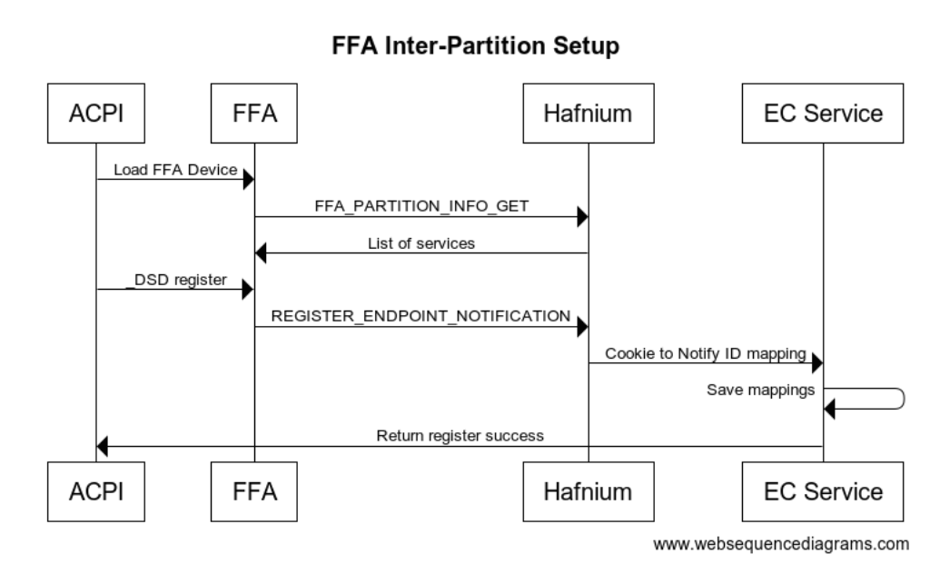
In the above example we indicate that the OS will handle 2 different notification events for UUID 330c1273-fde5-4757-9819-5b6539037502 which is our EC management UUID. FFA knows which secure partition this maps to based on the list of services for each SP it has retrieved. Rather than having to keep track of all the physical bits in the bitmask that are used the FFA driver keeps track of this and allows each service to create a list of virtual ID’s they need to handle. The FFA driver then maps this to one of the available bits in the hardware bitmask and passes this mapping down to the notification service running in a given SP.
Please refer to ARM documentation for full details on Inter-partition protocol DEN0077A_Firmware_Framework_Arm_A-profile_1.3
Input
| Parameter | Register | Value |
|---|---|---|
| FFA_MSG_SEND_DIRECT_REQ2 | X0 | 0xC400008D |
| Sender/Receiver Id | X1 | Bits[31:16]: Sender endpoint ID Bits[15:0]: Receiver endpoint ID |
| Protocol UUID low | X2 | Bytes[0..7] of Inter-partition setup protocol UUID |
| Protocol UUID high | X3 | Bytes[8..15] of Inter-partition setup protocol UUID |
| Reserved SBZ | X4 | 0x0 |
| Sender UUID low | X5 | Bytes[0..7] of service UUID |
| Sender UUID high | X6 | Bytes[8..15] of service UUID |
| Receiver UUID low | X7 | Bytes[0..7] of service UUID |
| Receiver UUID high | X8 | Bytes[8..15] of service UUID |
| Message Information | X9 | Bits[63:9]: Reserved MBZ Bit[8]: Message Direction - b'0 Request Message Bits[7:3]: Reserved MBZ Bits[2:0]: Message ID - b'010: Notification registration for a service |
| Cookie Information | X10 | Bits[63:9]: Bits[63:9]: Reserved MBZ Bits[8:0]: Count of (cookie,notification ID) tuples - 1 <= Count <= 7 |
| Tuple Mapping | X11-xX17 | Bits[63:32]: Cookie value Bits[31:23]: Notification ID associated with cookie Bits[22:1]: Reserved MBZ Bit[0]: Per-vcpu notification flag - b'0: Notification is a global notification - b'1: Notification is per-vcpu notification |
Output
| Parameter | Register | Value |
|---|---|---|
| FFA_MSG_SEND_DIRECT_RESP2 | X0 | 0xC400008E |
| Sender/Receiver Id | X1 | Bits[31:16]: Sender endpoint ID Bits[15:0]: Receiver endpoint ID |
| Protocol UUID low | X2 | Bytes[0..7] of Inter-partition setup protocol UUID |
| Protocol UUID high | X3 | Bytes[8..15] of Inter-partition setup protocol UUID |
| Reserved SBZ | X4 | 0x0 |
| Sender UUID low | X5 | Bytes[0..7] of service UUID |
| Sender UUID high | X6 | Bytes[8..15] of service UUID |
| Receiver UUID low | X7 | Bytes[0..7] of service UUID |
| Receiver UUID high | X8 | Bytes[8..15] of service UUID |
| Message Information | X9 | Bits[63:9]: Reserved MBZ Bit[8]: Message Direction - b'1 Response Message Bits[7:3]: Reserved MBZ Bits[2:0]: Message ID - b'010: Notification registration for a service |
| Cookie Information | X10 | Bits[63:9]: Bits[63:9]: Reserved MBZ Bits[8:0]: Count of (cookie,notification ID) tuples - 1 <= Count <= 7 |
| Tuple Mapping | X11-xX17 | Bits[63:32]: Cookie value Bits[31:23]: Notification ID associated with cookie Bits[22:1]: Reserved MBZ Bit[0]: Per-vcpu notification flag - b'0: Notification is a global notification - b'1: Notification is per-vcpu notification |
Note this NOTIFICATION_REGISTER request is sent to the Inter-Partition Service UUID in the SP. The UUID of the service that the notifications are for are stored in X5/X6 registers shown above.
The UUID for notification service is {e474d87e-5731-4044-a727-cb3e8cf3c8df} which is stored in X2/X3.
Notification Events
All notification events sent from all secure partitions are passed back through the FFA driver. The notification calls the _DSM method. Function 0 is always a bitmap of all the other functions supported. We must support at least Query and Notify. The UUID is stored in Arg0 and the notification cookie is stored in Arg3 when Arg2 is 11.
Method(_DSM, 0x4, NotSerialized)
{
// Arg0 - UUID 0194daab-ab08-7d5e-aea3-854bc457606a
// Arg1 - Revision
// Arg2: Function Index
// 0 - Query
// 1 - Notify
// 2 - binding failure
// 3 - infra failure
// Arg3 - Data
//
// Device specific method used to query
// configuration data. See ACPI 5.0 specification
// for further details.
//
If(LEqual(Arg0, Buffer(0x10) {
//
// UUID: {0194daab-ab08-7d5e-aea3-854bc457606a}
//
0x01, 0x94, 0xda, 0xab, 0xab, 0x08, 0x7d, 0x5e, 0xae, 0xa3, 0x85, 0x4b, 0xc4, 0x57, 0x60, 0x6a
}))
{
// Query Function
If(LEqual(Arg2, 0x0))
{
Return(Buffer(One) { 0x0f }) // Bitmask Query + Notify + binding failure + infra failure
}
// Notify Function
If(LEqual(Arg2, 0x1))
{
// Arg3 - Package {UUID, Cookie}
Store(DeRefOf(Index(Arg3,1)), \_SB.ECT0.NEVT )
}
// Binding Failure
If(LEqual(Arg2, 0x2))
{
// Arg3 Binding failure details
}
// Infra Failure
If(LEqual(Arg2, 0x3))
{
// Arg3 Infra failure details
}
}
Return(Buffer(One) { 0x00 })
}
The following is the call flow showing a secure interrupt arriving to the EC service which results in a notification back to ACPI. The notification payload can optionally be written to a shared buffer or ACPI can make another call back into EC service to retrieve the notification details.
In the _DSM, Arg2=1, Arg3 only contains the ID of the notification and no other payload, so both ACPI and the EC service must be designed either with shared memory buffer or a further notify data packet.
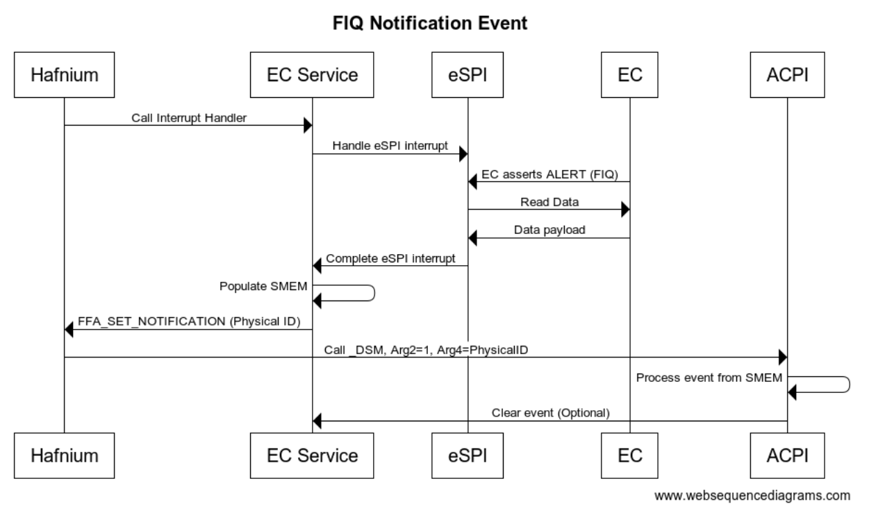
Runtime Requests
During runtime the non-secure side uses FFA_MSG_SEND_DIRECT_REQ2 requests to send requests to a given service within an SP. Any request that is expected to take longer than 1 ms should yield control back to the OS by calling FFA_YIELD within the service. When FFA_YIELD is called it will return control back to the OS to continue executing but the corresponding ACPI thread will be blocked until the original FFA request completes with DIRECT_RSP2. Note this creates a polling type interface where the OS will resume the SP thread after the timeout specified. The following is sample call sequence.
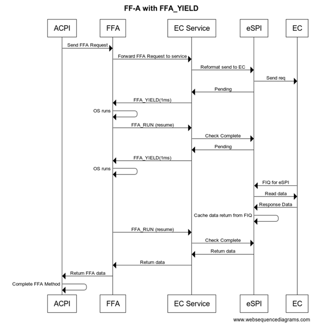
FFA Example Data Flow
For an example let’s take the battery status request _BST and follow data through.
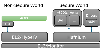
FFA_REQ_PACKET req = {
0x0, // Initialize to no error
0x0, // Let the OS populate the sender/receiver ID
{0x25,0xcb,0x52,0x07,0xac,0x36,0x42,0x7d,0xaa,0xef,0x3a,0xa7,0x88,0x77,0xd2,0x7e},
0x2 // EC_BAT_GET_BST
}
The equivalent to write this data into a BUFF in ACPI is as follows
CreateDwordField(BUFF,0,STAT) // Out – Status for req/rsp
CreateField(BUFF,64,64,RECV) // In/Out – Sender/Receiver ID
CreateField(BUFF,128,128,UUID) // UUID of service
CreateField(BUFF,256,8,CMDD) // In – First byte of command
CreateField(BUFF,256,128,BSTD) // Out – Raw data response 4 DWords
Store(0x2, CMDD)
Store(ToUUID ("25cb5207-ac36-427d-aaef-3aa78877d27e"), UUID)
Store(Store(BUFF, \\_SB_.FFA0.FFAC), BUFF)
The ACPI interpreter when walking through this code creates a buffer and populates the data into buffer. The last line indicates to send this buffer over FFA interface.
ACPI calls into the FFA interface to send the data over to the secure world EC Service
typedef struct _FFA_INTERFACE {
ULONG Version;
PFFA_MSG_SEND_DIRECT_REQ2 SendDirectReq2;
} FFA_INTERFACE, PFFA_INTERFACE;
FFA Parsing
FFA is in charge of sending the SMC over to the secure world and routing to the correct service based on UUID.
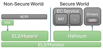
X0 = SEND_DIRECT_REQ2 SMC command ID
X1 = Source ID and Destination ID
X2 = UUID Low
X3 = UUID High
X4-X17 = rawdata
Note: The status and length are not passed through to the secure world they are consumed only be ACPI.
HyperV and Monitor have a chance to filter or deny the request, but in general just pass the SMC request through to Hafnium
Hafnium extracts the data from the registers into an sp_msg structure which is directly mapping contents from x0-x17 into these fields.
pub struct FfaParams {
pub x0: u64,
pub x1: u64,
pub x2: u64,
pub x3: u64,
pub x4: u64,
pub x5: u64,
pub x6: u64,
pub x7: u64,
pub x8: u64,
pub x9: u64,
pub x10: u64,
pub x11: u64,
pub x12: u64,
pub x13: u64,
pub x14: u64,
pub x15: u64,
pub x16: u64,
pub x17: u64,
}
The EC service receives all direct messages through the odp-ffa crate in DirectMessage. You will find this conversion into the RegisterPayload here.
fn try_from(value: SmcParams) -> Result<Self, Self::Error> {
let source_id = (value.x1 & 0xFFFF) as u16;
let destination_id = (value.x1 >> 16) as u16;
let uuid_high = u64::from_be(value.x2);
let uuid_low = u64::from_be(value.x3);
let uuid = Uuid::from_u64_pair(uuid_high, uuid_low);
// x4-x17 are for payload (14 registers)
let payload_regs = [
value.x4, value.x5, value.x6, value.x7, value.x8, value.x9, value.x10, value.x11, value.x12, value.x13,
value.x14, value.x15, value.x16, value.x17,
];
let payload_bytes_iter = payload_regs.iter().flat_map(|®| u64::to_le_bytes(reg).into_iter());
let payload = RegisterPayload::from_iter(payload_bytes_iter);
Ok(DirectMessage {
source_id,
destination_id,
uuid,
payload,
})
}
The destination_id is used to route the message to the correct SP, this is based on the ID field in the DTS description file. Eg: id = <0x8001>;
Embassy and Scheduling
The Secure Partition uses embassy as the scheduler for secure partition. This allows us to use await and do useful work while waiting for events even when we only are single threaded.
Embassy depeneds on timers and interrupts for signalling events. When we don't have any work to do we still in the poll loop today. Optimizations can be made to yield control back to non-secure world in these situations.
EC Service Parsing
Within the EC partition there are several services that register their UUID to receive messages. You will find the main message loop and registration of each service in the embassy_main entry.
service_list![
ec_service_lib::services::Thermal::new(),
ec_service_lib::services::Battery::new(),
ec_service_lib::services::FwMgmt::new(),
ec_service_lib::services::Notify::new()
]
.run_message_loop()
.await
.expect("Error in run_message_loop");
Each service must implement the following 3 functions to register and allow it to recieve direct messages. The following is example implementation of the notification service entry.
const UUID: Uuid = uuid!("e474d87e-5731-4044-a727-cb3e8cf3c8df");
impl Service for Notify {
fn service_name(&self) -> &'static str {
"Notify"
}
fn service_uuid(&self) -> Uuid {
UUID
}
async fn ffa_msg_send_direct_req2(&mut self, msg: MsgSendDirectReq2) -> Result<MsgSendDirectResp2> {
let req: NotifyReq = msg.clone().into();
debug!("Received notify command: {:?}", req.msg_info.message_id());
let payload = match req.msg_info.message_id() {
MessageID::Setup => RegisterPayload::from(self.nfy_setup(req)),
MessageID::Destroy => RegisterPayload::from(self.nfy_destroy(req)),
_ => {
error!("Unknown Notify Command: {:?}", req.msg_info.message_id());
return Err(odp_ffa::Error::Other("Unknown Notify Command"));
}
};
Ok(MsgSendDirectResp2::from_req_with_payload(&msg, payload))
}
}
Large Data Transfers
When making an FFA_MSG_SEND_DIRECT_REQ2 call the data is stored in registers X0-X17. X0-X3 are reserved to store the Function Id, Source Id, Destination Id and UUID. This leaves X4-X17 or 112 bytes. For larger messages they either need to be broken into multiple pieces or make use of a shared buffer between the OS and Secure Partition.
Shared Buffer Definitions
To create a shared buffer you need to modify the dts file for the secure partition to include mapping to your buffer.
ns_comm_buffer {
description = "ns-comm";
base-address = <0x00000100 0x60000000>;
pages-count = <0x8>;
attributes = <NON_SECURE_RW>;
};
During UEFI Platform initialization you will need to do the following steps, see the FFA specification for more details on these commands
- FFA_MAP_RXTX_BUFFER
- FFA_MEM_SHARE
- FFA_MSG_SEND_DIRECT_REQ2 (EC_CAP_MEM_SHARE)
- FFA_UNMAP_RXTX_BUFFER
The RXTX buffer is used during larger packet transfers but can be overridden and updated by the framework. The MEM_SHARE command uses the RXTX buffer so we first map that buffer then populate our memory descriptor requests to the TX_BUFFER and send to Hafnium. After sending the MEM_SHARE request we need to instruct our SP to retrieve this memory mapping request. This is done through our customer EC_CAP_MEM_SHARE request where we describe the shared memory region that UEFI has donated. From there we call FFA_MEM_RETRIEVE_REQ to map the shared memory that was described to Hafnium. After we are done with the RXTX buffers we must unmap them as the OS will re-map new RXTX buffers. From this point on both Non-secure and Secure side will have access to this shared memory buffer that was allocated.
Async Transfers
All services are single threaded by default. Even when doing FFA_YIELD it does not allow any new content to be executed within the service. If you need your service to be truly asynchronous you must have commands with delayed responses.
There is no packet identifier by default and tracking of requests and completion by FFA, so the sample solution given here is based on shared buffers defined in previous section and existing ACPI and FFA functionality.
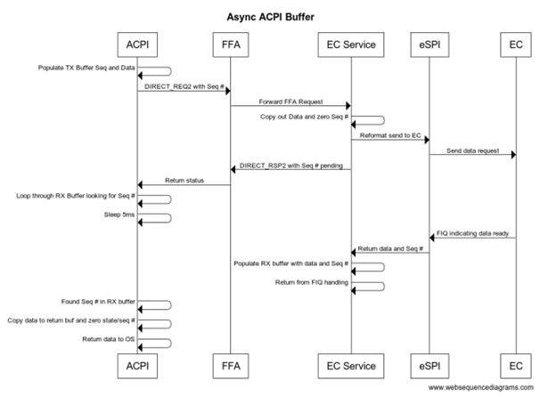
Inside of our FFA functions rather than copying our data payload into the direct registers we define a queue in shared memory and populate the actual data into this queue entry. In the FFA_MSG_SEND_DIRECT_REQ2 we populate an ASYNC command ID (0x0) along with the seq #. The seq # is then used by the service to locate the request in the TX queue. We define a separate queue for RX and TX so we don’t need to synchronize between OS and secure partition.
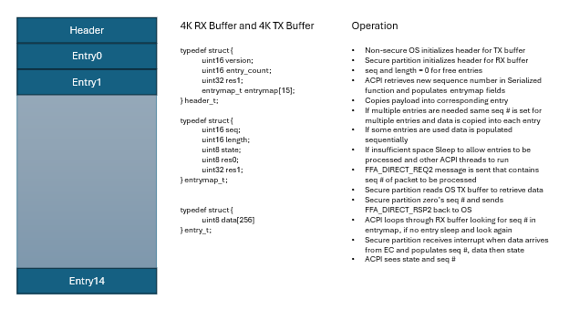
ACPI Structures and Methods for Asynchronous
The SMTX is shared memory TX region definition
// Shared memory regions and ASYNC implementation
OperationRegion (SMTX, SystemMemory, 0x10060000000, 0x1000)
// Store our actual request to shared memory TX buffer
Field (SMTX, AnyAcc, NoLock, Preserve)
{
TVER, 16,
TCNT, 16,
TRS0, 32,
TB0, 64,
TB1, 64,
TB2, 64,
TB3, 64,
TB4, 64,
TB5, 64,
TB6, 64,
TB7, 64,
Offset(0x100), // First Entry starts at 256 byte offset each entry is 256 bytes
TE0, 2048,
TE1, 2048,
TE2, 2048,
TE3, 2048,
TE4, 2048,
TE5, 2048,
TE6, 2048,
TE7, 2048,
}
The QTXB method copies data into first available entry in the TX queue and returns sequence number used.
// Arg0 is buffer pointer
// Arg1 is length of Data
// Return Seq \#
Method(QTXB, 0x2, Serialized) {
Name(TBX, 0x0)
Store(Add(ShiftLeft(1,32),Add(ShiftLeft(Arg1,16),SEQN)),TBX)
Increment(SEQN)
// Loop until we find a free entry to populate
While(One) {
If(LEqual(And(TB0,0xFFFF),0x0)) {
Store(TBX,TB0); Store(Arg0,TE0); Return( And(TBX,0xFFFF) )
}
If(LEqual(And(TB1,0xFFFF),0x0)) {
Store(TBX,TB1); Store(Arg0,TE1); Return( And(TBX,0xFFFF) )
}
If(LEqual(And(TB2,0xFFFF),0x0)) {
Store(TBX,TB2); Store(Arg0,TE2); Return( And(TBX,0xFFFF) )
}
If(LEqual(And(TB3,0xFFFF),0x0)) {
Store(TBX,TB3); Store(Arg0,TE3); Return( And(TBX,0xFFFF) )
}
If(LEqual(And(TB4,0xFFFF),0x0)) {
Store(TBX,TB4); Store(Arg0,TE4); Return( And(TBX,0xFFFF) )
}
If(LEqual(And(TB5,0xFFFF),0x0)) {
Store(TBX,TB5); Store(Arg0,TE5); Return( And(TBX,0xFFFF) )
}
If(LEqual(And(TB6,0xFFFF),0x0)) {
Store(TBX,TB6); Store(Arg0,TE6); Return( And(TBX,0xFFFF) )
}
If(LEqual(And(TB7,0xFFFF),0x0)) {
Store(TBX,TB7); Store(Arg0,TE7); Return( And(TBX,0xFFFF) )
}
Sleep(5)
}
}
The SMRX is shared memory region for RX queues
// Shared memory region
OperationRegion (SMRX, SystemMemory, 0x10060001000, 0x1000)
// Store our actual request to shared memory TX buffer
Field (SMRX, AnyAcc, NoLock, Preserve)
{
RVER, 16,
RCNT, 16,
RRS0, 32,
RB0, 64,
RB1, 64,
RB2, 64,
RB3, 64,
RB4, 64,
RB5, 64,
RB6, 64,
RB7, 64,
Offset(0x100), // First Entry starts at 256 byte offset each entry is 256 bytes
RE0, 2048,
RE1, 2048,
RE2, 2048,
RE3, 2048,
RE4, 2048,
RE5, 2048,
RE6, 2048,
RE7, 2048,
}
The RXDB function takes sequence number as input and will keep looping through all the entries until we see packet has completed. Sleeps for 5ms between each iteration to allow the OS to do other things and other ACPI threads can run.
// Allow multiple threads to wait for their SEQ packet at once
// If supporting packet \> 256 bytes need to modify to stitch together packet
Method(RXDB, 0x1, Serialized) {
Name(BUFF, Buffer(256){})
// Loop forever until we find our seq
While (One) {
If(LEqual(And(RB0,0xFFFF),Arg0)) {
CreateField(BUFF, 0, Multiply(And(ShiftRight(RB0,16),0xFFFF),8), XB0)
Store(RE0,BUFF); Store(0,RB0); Return( XB0 )
}
If(LEqual(And(RB1,0xFFFF),Arg0)) {
CreateField(BUFF, 0, Multiply(And(ShiftRight(RB1,16),0xFFFF),8), XB1)
Store(RE1,BUFF); Store(0,RB1); Return( XB1 )
}
If(LEqual(And(RB2,0xFFFF),Arg0)) {
CreateField(BUFF, 0, Multiply(And(ShiftRight(RB2,16),0xFFFF),8), XB2)
Store(RE2,BUFF); Store(0,RB2); Return( XB2 )
}
If(LEqual(And(RB3,0xFFFF),Arg0)) {
CreateField(BUFF, 0, Multiply(And(ShiftRight(RB3,16),0xFFFF),8), XB3)
Store(RE3,BUFF); Store(0,RB3); Return( XB3 )
}
If(LEqual(And(RB4,0xFFFF),Arg0)) {
CreateField(BUFF, 0, Multiply(And(ShiftRight(RB4,16),0xFFFF),8), XB4)
Store(RE4,BUFF); Store(0,RB4); Return( XB4 )
}
If(LEqual(And(RB5,0xFFFF),Arg0)) {
CreateField(BUFF, 0, Multiply(And(ShiftRight(RB5,16),0xFFFF),8), XB5)
Store(RE5,BUFF); Store(0,RB5); Return( XB5 )
}
If(LEqual(And(RB6,0xFFFF),Arg0)) {
CreateField(BUFF, 0, Multiply(And(ShiftRight(RB6,16),0xFFFF),8), XB6)
Store(RE6,BUFF); Store(0,RB6); Return( XB6 )
}
If(LEqual(And(RB7,0xFFFF),Arg0)) {
CreateField(BUFF, 0, Multiply(And(ShiftRight(RB7,16),0xFFFF),8), XB7)
Store(RE7,BUFF); Store(0,RB7); Return( XB7 )
}
Sleep(5)
}
// If we get here didn't find a matching sequence number
Return (Ones)
}
The following is sample code to transmit a ASYNC request and wait for the data in the RX buffer.
Method(ASYC, 0x0, Serialized) {
If(LEqual(\\_SB.FFA0.AVAL,One)) {
CreateDwordField(BUFF,0,STAT) // Out – Status for req/rsp
CreateField(BUFF,128,128,UUID) // UUID of service
CreateByteField(BUFF,32,CMDD) // Command register
CreateWordField(BUFF,33,BSQN) // Sequence Number
Store(0x0, CMDD) // EC_ASYNC command
Local0 = QTXB(BUFF,20) // Copy data to our queue entry and get back SEQN
Store(Local0,BSQN) // Sequence packet to read from shared memory
Store(ToUUID("330c1273-fde5-4757-9819-5b6539037502"), UUID)
Store(Store(BUFF, \\_SB_.FFA0.FFAC), BUFF)
If(LEqual(STAT,0x0) ) // Check FF-A successful?
{
Return (RXDB(Local0)) // Loop through our RX queue till packet completes
}
}
Recovery and Errors
The eSPI or bus driver is expected to detect if the EC is not responding and retry. The FFA driver will report back in the status byte if it cannot successfully talk to the secure world. If there are other failures generally they should be returned back up through ACPI with a value of (Ones) to indicate failure condition. This may cause some features to work incorrectly.
It is also expected that the EC has a watchdog if something on the EC is hung it should reset and reload on its own. The EC is also responsible for monitoring that the system is running within safe parameters. The thermal requests and queries are meant to be advisory in nature and EC should be able to run independently and safely without any intervention from the OS.
EC Firmware Management
This service is to provide details about the security state, supported features, debug, firmware version and firmware update functionality.
NIST SP 800-193 compliance requires failsafe update of primary and backup EC FW images. EC should run from primary partition while writing backup partitions and then change flag to indicate backup becomes primary and primary becomes backup.
| Capability Command | Description |
|---|---|
| EC_CAP_GET_FW_STATE = 0x1 | Return details of FW in EC, DICE, Secure Boot, Version, etc |
| EC_CAP_GET_SVC_LIST = 0x2 | Get list of services/features that this EC supports |
| EC_CAP_GET_BID = 0x3 | Read Board ID that is used customized behavior |
| EC_CAP_TEST_NFY = 0x4 | Create test notification event |
Get Firmware State
Returns start of the overall EC if DICE and secure boot was enabled, currently running firmware version, EC status like boot failures.
Secure Boot and DICE
DICE is a specification from the Trusted Computing Group that allows the MCU to verify the signature of the code that it is executing, thereby establishing trust in the code. To do this, it has a primary bootloader program that reads the firmware on flash and using a key that is only accessible by the ROM bootloader, can verify the authenticity of the firmware.
Trusted Platform Architecture - Device Identity Composition Engine (trustedcomputinggroup.org)
Input Parameters
None
Output Parameters
| Field | Bits | Description |
|---|---|---|
| FWVersion | 16 | Version of FW running on EC |
| SecureState | 8 | Bit mask representing the secure state of the device 0 – DICE is enabled 1 – Firmware is signed |
| BootStatus | 8 | Boot status and error codes 0 = SUCCESS |
FFA ACPI Example
Method (TFWS) {
// Check to make sure FFA is available and not unloaded
If(LEqual(\\_SB.FFA0.AVAL,One)) {
CreateQwordField(BUFF,0,STAT) // Out – Status for req/rsp
CreateField(BUFF,128,128,UUID) // UUID of service
CreateByteField(BUFF,32, CMDD) // In – First byte of command
CreateDwordField(BUFF,32,FWSD) // Out – Raw data response (overlaps with CMDD)
Store(ToUUID("330c1273-fde5-4757-9819-5b6539037502"), UUID) // Management
Store(0x1, CMDD) // EC_CAP_GET_FW_STATE
Store(Store(BUFF, \_SB_.FFA0.FFAC), BUFF)
If(LEqual(STAT,0x0) ) // Check FF-A successful?
{
Return (FWSD)
}
}
Return(Zero)
}
Get Features Supported
Get a list of services/features supported by this EC. Several features like HID devices are optional and may not be present. OEM services may also be added to this list as additional features supported.
Input Parameters
None
Output Parameters
| Field | Bits | Description |
|---|---|---|
| DebugMask | 16 | 0 - Supports reset reason 1 - Supports debug tracing |
| BatteryMask | 8 | 0 - Battery 0 present 1 - Battery 1 present ... |
| FanMask | 8 | 0 - Fan 0 present 1 - Fan 1 present ... |
| ThermalMask | 8 | 0 - Skin TZ present |
| HIDMask | 8 | 0 - HID0 present 1 - HID1 present ... |
| KeyMask | 16 | 0 - Power key present 1 - LID switch present 2 - VolUp key present 3 - VolDown key present 4 - Camera key present |
FFA ACPI Example
Method(TFET, 0x0, Serialized) {
If(LEqual(\\_SB.FFA0.AVAL,One)) {
CreateQwordField(BUFF,0,STAT) // Out – Status for req/rsp
CreateField(BUFF,128,128,UUID) // UUID of service
CreateByteField(BUFF,32, CMDD) // In – First byte of command
CreateWordField(BUFF,32,FET0) // DebugMask
CreateByteField(BUFF,34,FET1) // BatteryMask
CreateByteField(BUFF,35,FET2) // FanMask
CreateByteField(BUFF,36,FET3) // ThermalMask
CreateByteField(BUFF,37,FET4) // HIDMask
CreateWordField(BUFF,38,FET5) // KeyMask
Store(0x2, CMDD) // EC_CAP_GET_SVC_LIST
Store(ToUUID("330c1273-fde5-4757-9819-5b6539037502"), UUID)
Store(Store(BUFF, \\_SB_.FFA0.FFAC), BUFF)
If(LEqual(STAT,0x0) ) {
Return (package () {FET0,FET1,FET2,FET3,FET4,FET5})
}
}
Return(package () {0,0,0,0,0,0,0})
}
Get Board ID
EC is often used to read pins or details to determine the HW configuration based on GPIO’s or ADC values. This ID allows SW to change behavior depending on this HW version information.
Input Parameters
None
Output Parameters
| Field | Bits | Description |
|---|---|---|
| BoardID | 64 | Vendor defined |
FFA ACPI Example
Method(TBID, 0x0, Serialized) {
If(LEqual(\\_SB.FFA0.AVAL,One)) {
CreateQwordField(BUFF,0,STAT) // Out – Status for req/rsp
CreateField(BUFF,128,128,UUID) // UUID of service
CreateByteField(BUFF,32, CMDD) // In – First byte of command
CreateDwordField(BUFF,32,BIDD) // Output Data
Store(0x3, CMDD) // EC_CAP_GET_BID
Store(ToUUID("330c1273-fde5-4757-9819-5b6539037502"), UUID)
Store(Store(BUFF, \\_SB_.FFA0.FFAC), BUFF)
If(LEqual(STAT,0x0) ) {
Return (BIDD)
} else {
}
Return(Zero)
}
Firmware Update
This should initiate update of a particular firmware in the backup partition to provide NIST SP 800-193 failsafe compliance. EC firmware update is planned to be handled through CFU. Further details are available in CFU specification.
EC Power Service
System Power State
OS calls in to notify EC or a change in system power state.
Perform appropriate power sequencing for the SoC from low power states (S3, S4, S5) to S0, and from S0 to low power states
Battery Service
Battery control is monitored through the Modern Power Thermal Framework (MPTF). See this specification for further details on implementing firmware for these features. This section outlines the interface required in ACPI for this framework to function.
Note: There is an issue with ACPI and embedded packages return Package() {BST0,BST1,BST2,BST3} returns "BST0","BST1","BST2","BST3" rather than the values pointed to by these variables. As such we need to create a global Name for BSTD and initialize default values and update these fields like the following.
Name (BSTD, Package (4) {
0x2,
0x500,
0x10000,
0x3C28
})
...
BSTD[0] = BST0
BSTD[1] = BST1
BSTD[2] = BST2
BSTD[3] = BST3
Return(BSTD)
| Command | Description |
|---|---|
| EC_BAT_GET_BIX = 0x1 | Returns information about battery, model, serial number voltage. Note this is a superset of BIF. (MPTF) |
| EC_BAT_GET_BST = 0x2 | Get Battery Status, must also have notify event on state change. (MPTF) |
| EC_BAT_GET_PSR = 0x3 | Returns whether this power source device is currently online. (MPTF) |
| EC_BAT_GET_PIF = 0x4 | Returns static information about a power source. (MPTF) |
| EC_BAT_GET_BPS = 0x5 | Power delivery capabilities of battery at present time. (MPTF) |
| EC_BAT_SET_BTP = 0x6 | Set battery trip point to generate SCI event (MPTF) |
| EC_BAT_SET_BPT = 0x7 | Set Battery Power Threshold (MPTF) |
| EC_BAT_GET_BPC = 0x8 | Returns static variables that are associated with system power characteristics on the battery path and power threshold support settings. (MPTF) |
| EC_BAT_SET_BMC= 0x9 | Battery Maintenance Control |
| EC_BAT_GET_BMD = 0xA | Returns battery information regarding charging and calibration |
| EC_BAT_GET_BCT = 0xB | Returns battery charge time. |
| EC_BAT_GET_BTM = 0xC | Get estimated runtime of battery while discharging |
| EC_BAT_SET_BMS = 0xD | Sets battery capacity sampling time in ms |
| EC_BAT_SET_BMA = 0xE | Battery Measurement Average Interval |
| EC_BAT_GET_STA = 0xF | Get battery availability |
EC_BAT_GET_BIX
Returns information about battery, model, serial number voltage etc
Input Parameters
None
Output Parameters
Should return structure as defined by ACPI specification
10. Power Source and Power Meter Devices — ACPI Specification 6.4 documentation
FFA ACPI Example
Name (BIXD, Package(21) {
0,
0,
0x15F90,
0x15F90,
1,
0x3C28,
0x8F,
0xE10,
1,
0x17318,
0x03E8,
0x03E8,
0x03E8,
0x03E8,
0x380,
0xE1,
" ",
" ",
" ",
" ",
0
})
Method (_BIX, 0, Serialized) {
// Check to make sure FFA is available and not unloaded
If(LEqual(\_SB.FFA0.AVAL,One)) {
CreateDwordField(BUFF,0,STAT) // Out – Status for req/rsp
CreateField(BUFF,128,128,UUID) // UUID of service
CreateByteField(BUFF,32,CMDD) // In – First byte of command
CreateDwordField(BUFF,32,BIX0) // Out – Revision
CreateDwordField(BUFF,36,BIX1) // Out – Power Unit
CreateDwordField(BUFF,40,BIX2) // Out – Design Capacity
CreateDwordField(BUFF,44,BIX3) // Out – Last Full Charge Capacity
CreateDwordField(BUFF,48,BIX4) // Out – Battery Technology
CreateDwordField(BUFF,52,BIX5) // Out – Design Voltage
CreateDwordField(BUFF,56,BIX6) // Out – Design Capacity of Warning
CreateDwordField(BUFF,60,BIX7) // Out – Design Capacity of Low
CreateDwordField(BUFF,64,BIX8) // Out – Cycle Count
CreateDwordField(BUFF,68,BIX9) // Out – Measurement Accuracy
CreateDwordField(BUFF,72,BI10) // Out – Max Sampling Time
CreateDwordField(BUFF,76,BI11) // Out – Min Sampling Time
CreateDwordField(BUFF,80,BI12) // Out – Max Averaging Internal
CreateDwordField(BUFF,84,BI13) // Out – Min Averaging Interval
CreateDwordField(BUFF,88,BI14) // Out – Battery Capacity Granularity 1
CreateDwordField(BUFF,92,BI15) // Out – Battery Capacity Granularity 2
CreateField(BUFF,768,64,BI16) // Out – Model Number
CreateField(BUFF,832,64,BI17) // Out – Serial number
CreateField(BUFF,896,64,BI18) // Out – Battery Type
CreateField(BUFF,960,64,BI19) // Out – OEM Information
CreateDwordField(BUFF,128,BI20) // Out – OEM Information
Store(0x1, CMDD) //EC_BAT_GET_BIX
Store(ToUUID("25cb5207-ac36-427d-aaef-3aa78877d27e"), UUID)
Store(Store(BUFF, \_SB_.FFA0.FFAC), BUFF)
If(LEqual(STAT,0x0) ) // Check FF-A successful?
{
BIXD[0] = BIX0
BIXD[1] = BIX1
BIXD[2] = BIX2
BIXD[3] = BIX3
BIXD[4] = BIX4
BIXD[5] = BIX5
BIXD[6] = BIX6
BIXD[7] = BIX7
BIXD[8] = BIX8
BIXD[9] = BIX9
BIXD[10] = BI10
BIXD[11] = BI11
BIXD[12] = BI12
BIXD[13] = BI13
BIXD[14] = BI14
BIXD[15] = BI15
BIXD[16] = BI16
BIXD[17] = BI17
BIXD[18] = BI18
BIXD[19] = BI19
BIXD[20] = BI20
}
}
Return(BIXD)
}
EC_BAT_GET_BST
This object returns the present battery status. Whenever the Battery State value changes, the system will generate an SCI to notify the OS.
Input Parameters
None
Output Parameters
Should return structure as defined by ACPI specification
10. Power Source and Power Meter Devices — ACPI Specification 6.4 documentation
FFA ACPI Example
Name (BSTD, Package (4) {
0x2,
0x500,
0x10000,
0x3C28
})
Method (_BST, 0, Serialized) {
// Check to make sure FFA is available and not unloaded
If(LEqual(\_SB.FFA0.AVAL,One)) {
CreateDwordField(BUFF,0,STAT) // Out – Status for req/rsp
CreateField(BUFF,128,128,UUID) // UUID of service
CreateByteField(BUFF,32,CMDD) // In – First byte of command
CreateDwordField(BUFF,32,BST0) // Out – Battery State DWord
CreateDwordField(BUFF,36,BST1) // Out – Battery Rate DWord
CreateDwordField(BUFF,40,BST2) // Out – Battery Reamining Capacity DWord
CreateDwordField(BUFF,44,BST3) // Out – Battery Voltage DWord
Store(0x2, CMDD) //EC_BAT_GET_BST
Store(ToUUID("25cb5207-ac36-427d-aaef-3aa78877d27e"), UUID)
Store(Store(BUFF, \_SB_.FFA0.FFAC), BUFF)
If(LEqual(STAT,0x0) ) // Check FF-A successful?
{
BSTD[0] = BST0
BSTD[1] = BST1
BSTD[2] = BST2
BSTD[3] = BST3
}
}
Return(BSTD)
}
EC_BAT_GET_PSR
Returns whether the power source device is currently in use. This can be used to determine if system is running off this power supply or adapter. On mobile systes this will report that the system is not running on the AC adapter if any of the batteries in the system is being forced to discharge. In systems that contains multiple power sources, this object reports the power source’s online or offline status.
Input Parameters
None
Output Parameters
Should return structure as defined by ACPI specification
10. Power Source and Power Meter Devices — ACPI Specification 6.4 documentation
FFA ACPI Example
Method (_PSR, 0, Serialized) {
// Check to make sure FFA is available and not unloaded
If(LEqual(\_SB.FFA0.AVAL,One)) {
CreateDwordField(BUFF,0,STAT) // Out – Status for req/rsp
CreateField(BUFF,128,128,UUID) // UUID of service
CreateByteField(BUFF,32,CMDD) // In – First byte of command
CreateDwordField(BUFF,32,PSR0) // Out – Power Source
Store(0x3, CMDD) //EC_BAT_GET_PSR
Store(ToUUID("25cb5207-ac36-427d-aaef-3aa78877d27e"), UUID)
Store(Store(BUFF, \_SB_.FFA0.FFAC), BUFF)
If(LEqual(STAT,0x0) ) // Check FF-A successful?
{
return(PSR0)
}
}
Return(0)
}
EC_BAT_GET_PIF
This object returns information about the Power Source, which remains constant until the Power Source is changed. When the power source changes, the platform issues a Notify(0x0) (Bus Check) to the Power Source device to indicate that OSPM must re-evaluate the _PIF object.
Input Parameters
None
Output Parameters
Should return structure as defined by ACPI specification
10. Power Source and Power Meter Devices — ACPI Specification 6.4 documentation
FFA ACPI Example
Name( PIFD, Package(6) {
0, // Out – Power Source State
0, // Out – Maximum Output Power
0, // Out – Maximum Input Power
" ", // Out – Model Number
" ", // Out – Serial Number
" " // Out – OEM Information
})
Method (_PIF, 0, Serialized) {
// Check to make sure FFA is available and not unloaded
If(LEqual(\_SB.FFA0.AVAL,One)) {
CreateDwordField(BUFF,0,STAT) // Out – Status for req/rsp
CreateField(BUFF,128,128,UUID) // UUID of service
CreateByteField(BUFF,32,CMDD) // In – First byte of command
CreateDwordField(BUFF,32,PIF0) // Out – Power Source State
CreateDwordField(BUFF,36,PIF1) // Out – Maximum Output Power
CreateDwordField(BUFF,40,PIF2) // Out – Maximum Input Power
CreateField(BUFF,352,64,PIF3) // Out – Model Number
CreateField(BUFF,416,64,PIF4) // Out – Serial Number
CreateField(BUFF,480,64,PIF5) // Out – OEM Information
Store(0x4, CMDD) //EC_BAT_GET_PIF
Store(ToUUID("25cb5207-ac36-427d-aaef-3aa78877d27e"), UUID)
Store(Store(BUFF, \_SB_.FFA0.FFAC), BUFF)
If(LEqual(STAT,0x0) ) // Check FF-A successful?
{
PIFD[0] = PIF0
PIFD[1] = PIF1
PIFD[2] = PIF2
PIFD[3] = PIF3
PIFD[4] = PIF4
PIFD[5] = PIF5
}
}
Return(PIFD)
}
EC_BAT_GET_BPS
This optional object returns the power delivery capabilities of the battery at the present time. If multiple batteries are present within the system, the sum of peak power levels from each battery can be used to determine the total available power.
Input Parameters
None
Output Parameters
Should return structure as defined by ACPI specification
FFA ACPI Example
Name( BPSD, Package(5) {
0, // Out – Revision
0, // Out – Instantaneous Peak Power Level
0, // Out – Instantaneous Peak Power Period
0, // Out – Sustainable Peak Power Level
0 // Out – Sustainable Peak Power Period
})
Method (_BPS, 0, Serialized) {
// Check to make sure FFA is available and not unloaded
If(LEqual(\_SB.FFA0.AVAL,One)) {
CreateDwordField(BUFF,0,STAT) // Out – Status for req/rsp
CreateField(BUFF,128,128,UUID) // UUID of service
CreateByteField(BUFF,32,CMDD) // In – First byte of command
CreateDwordField(BUFF,32,BPS0) // Out – Revision
CreateDwordField(BUFF,36,BPS1) // Out – Instantaneous Peak Power Level
CreateDwordField(BUFF,40,BPS2) // Out – Instantaneous Peak Power Period
CreateDwordField(BUFF,44,BPS3) // Out – Sustainable Peak Power Level
CreateDwordField(BUFF,48,BPS4) // Out – Sustainable Peak Power Period
Store(0x5, CMDD) //EC_BAT_GET_BPS
Store(ToUUID("25cb5207-ac36-427d-aaef-3aa78877d27e"), UUID)
Store(Store(BUFF, \_SB_.FFA0.FFAC), BUFF)
If(LEqual(STAT,0x0) ) // Check FF-A successful?
{
BPSD[0] = BPS0
BPSD[1] = BPS1
BPSD[2] = BPS2
BPSD[3] = BPS3
BPSD[4] = BPS4
}
}
Return(BPSD)
}
EC_BAT_SET_BTP
This object is used to set a trip point to generate an SCI whenever the Battery Remaining Capacity reaches or crosses the value specified in the _BTP object. Required on systems supporting Modern Standby
Platform design for modern standby | Microsoft Learn
Input Parameters
See ACPI documentation for details
10. Power Source and Power Meter Devices — ACPI Specification 6.4 documentation
Output Parameters
None
FFA ACPI Example
Method (_BTP, 1, Serialized) {
// Check to make sure FFA is available and not unloaded
If(LEqual(\_SB.FFA0.AVAL,One)) {
CreateDwordField(BUFF,0,STAT) // Out – Status for req/rsp
CreateField(BUFF,128,128,UUID) // UUID of service
CreateByteField(BUFF,32,CMDD) // In – First byte of command
CreateDwordField(BUFF,36,BTP0) // In - Trip point value
Store(0x6, CMDD) //EC_BAT_SET_BTP
Store(Arg0, BTP0)
Store(ToUUID("25cb5207-ac36-427d-aaef-3aa78877d27e"), UUID)
Store(Store(BUFF, \_SB_.FFA0.FFAC), BUFF)
If(LEqual(STAT,0x0) ) // Check FF-A successful?
{
return(Zero )
}
}
Return(Zero)
}
EC_BAT_GET_BPC
This optional object returns static values that are used to configure power threshold support in the platform firmware. OSPM can use the information to determine the capabilities of power delivery and threshold support for each battery in the system.
Input Parameters
None
Output Parameters
Should return structure as defined by ACPI specification
10. Power Source and Power Meter Devices — ACPI Specification 6.4 documentation
FFA ACPI Example
Name( BPCD, Package(4) {
1, // Out - Revision
0, // Out - Threshold support
8000, // Out - Max Inst peak power
2000 // Out - Max Sust peak power
})
Method (_BPC, 0, Serialized) {
// Check to make sure FFA is available and not unloaded
If(LEqual(\_SB.FFA0.AVAL,One)) {
CreateDwordField(BUFF,0,STAT) // Out – Status for req/rsp
CreateField(BUFF,128,128,UUID) // UUID of service
CreateByteField(BUFF,32,CMDD) // In – First byte of command
CreateDwordField(BUFF,32,BPC0) // Out - Revision
CreateDwordField(BUFF,36,BPC1) // Out - Threshold support
CreateDwordField(BUFF,40,BPC2) // Out - Max Inst peak power
CreateDwordField(BUFF,44,BPC3) // Out - Max Sust peak power
Store(0x8, CMDD) //EC_BAT_GET_BPC
Store(ToUUID("25cb5207-ac36-427d-aaef-3aa78877d27e"), UUID)
Store(Store(BUFF, \_SB_.FFA0.FFAC), BUFF)
If(LEqual(STAT,0x0) ) // Check FF-A successful?
{
BPCD[0] = BPC0
BPCD[1] = BPC1
BPCD[2] = BPC2
BPCD[3] = BPC3
}
}
Return(BPCD)
}
EC_BAT_SET_BPT
his optional object may be present under a battery device. OSPM must read _BPC first to determine the power delivery capability threshold support in the platform firmware and invoke this Method in order to program the threshold accordingly. If the platform does not support battery peak power thresholds, this Method should not be included in the namespace.
Input Parameters
See ACPI specification for input parameters
10. Power Source and Power Meter Devices — ACPI Specification 6.4 documentation
Output Parameters
Should return structure as defined by ACPI specification
10. Power Source and Power Meter Devices — ACPI Specification 6.4 documentation
FFA ACPI Example
Method (_BPT, 3, Serialized) {
// Check to make sure FFA is available and not unloaded
If(LEqual(\_SB.FFA0.AVAL,One)) {
CreateDwordField(BUFF,0,STAT) // Out – Status for req/rsp
CreateField(BUFF,128,128,UUID) // UUID of service
CreateByteField(BUFF,32,CMDD) // In – First byte of command
CreateDwordField(BUFF,36,BPT0) // In - Revision
CreateDwordField(BUFF,40,BPT1) // In - Threshold ID
CreateDwordField(BUFF,44,BPT2) // In - Threshold value
CreateDwordField(BUFF,32,BPTS) // Out - Trip point value
Store(0x7, CMDD) //EC_BAT_SET_BPT
Store(Arg0, BPT0)
Store(Arg1, BPT1)
Store(Arg2, BPT2)
Store(ToUUID("25cb5207-ac36-427d-aaef-3aa78877d27e"), UUID)
Store(Store(BUFF, \_SB_.FFA0.FFAC), BUFF)
If(LEqual(STAT,0x0) ) // Check FF-A successful?
{
return(BPTS)
}
}
Return(Zero)
}
EC_BAT_SET_BMC
This object is used to initiate calibration cycles or to control the charger and whether or not a battery is powering the system. This object is only present under a battery device if the _BMD Capabilities Flags field has bit 0, 1, 2, or 5 set.
Input Parameters
See ACPI specification for input parameter definition
10. Power Source and Power Meter Devices — ACPI Specification 6.4 documentation
Output Parameters
None
FFA ACPI Example
Method (_BMC, 1, Serialized) {
// Check to make sure FFA is available and not unloaded
If(LEqual(\_SB.FFA0.AVAL,One)) {
CreateDwordField(BUFF,0,STAT) // Out – Status for req/rsp
CreateField(BUFF,128,128,UUID) // UUID of service
CreateByteField(BUFF,32,CMDD) // In – First byte of command
CreateDwordField(BUFF,36,BMC0) // In - Feature control flags
Store(0x9, CMDD) //EC_BAT_SET_BMC
Store(Arg0, BMC0)
Store(ToUUID("25cb5207-ac36-427d-aaef-3aa78877d27e"), UUID)
Store(Store(BUFF, \_SB_.FFA0.FFAC), BUFF)
}
Return(Zero)
}
EC_BAT_GET_BMD
This optional object returns information about the battery’s capabilities and current state in relation to battery calibration and charger control features. If the _BMC object (defined below) is present under a battery device, this object must also be present. Whenever the Status Flags value changes, AML code will issue a Notify(battery_device, 0x82). In addition, AML will issue a Notify(battery_device, 0x82) if evaluating _BMC did not result in causing the Status Flags to be set as indicated in that argument to _BMC. AML is not required to issue Notify(battery_device, 0x82) if the Status Flags change while evaluating _BMC unless the change does not correspond to the argument passed to _BMC.
10. Power Source and Power Meter Devices — ACPI Specification 6.4 documentation
Input Parameters
None
Output Parameters
Should return structure as defined by ACPI specification
FFA ACPI Example
Name( BMDD, Package(5) {
0, // Out - Status
0, // Out - Capability Flags
0, // Out - Recalibrate count
0, // Out - Quick recal time
0 // Out - Slow recal time
})
Method (_BMD, 0, Serialized) {
// Check to make sure FFA is available and not unloaded
If(LEqual(\_SB.FFA0.AVAL,One)) {
CreateDwordField(BUFF,0,STAT) // Out – Status for req/rsp
CreateField(BUFF,128,128,UUID) // UUID of service
CreateByteField(BUFF,32,CMDD) // In – First byte of command
CreateDwordField(BUFF,32,BMD0) // Out - Status
CreateDwordField(BUFF,36,BMD1) // Out - Capability Flags
CreateDwordField(BUFF,40,BMD2) // Out - Recalibrate count
CreateDwordField(BUFF,44,BMD3) // Out - Quick recal time
CreateDwordField(BUFF,48,BMD4) // Out - Slow recal time
Store(0xa, CMDD) //EC_BAT_GET_BMD
Store(ToUUID("25cb5207-ac36-427d-aaef-3aa78877d27e"), UUID)
Store(Store(BUFF, \_SB_.FFA0.FFAC), BUFF)
If(LEqual(STAT,0x0) ) // Check FF-A successful?
{
BMDD[0] = BMD0
BMDD[1] = BMD1
BMDD[2] = BMD2
BMDD[3] = BMD3
BMDD[4] = BMD4
}
}
Return(BMDD)
}
EC_BAT_GET_BCT
When the battery is charging, this optional object returns the estimated time from present to when it is charged to a given percentage of Last Full Charge Capacity.
10. Power Source and Power Meter Devices — ACPI Specification 6.4 documentation
Input Parameters
Input parameters as described in ACPI specification.
Output Parameters
Should return structure as defined by ACPI specification
FFA ACPI Example
Method (_BCT, 1, Serialized) {
// Check to make sure FFA is available and not unloaded
If(LEqual(\_SB.FFA0.AVAL,One)) {
CreateDwordField(BUFF,0,STAT) // Out – Status for req/rsp
CreateField(BUFF,128,128,UUID) // UUID of service
CreateByteField(BUFF,32,CMDD) // In – First byte of command
CreateDwordField(BUFF,36,BCT0) // In - ChargeLevel
CreateDwordField(BUFF,32,BCTD) // Out - Result
Store(0xb, CMDD) //EC_BAT_GET_BCT
Store(Arg0, BCT0)
Store(ToUUID("25cb5207-ac36-427d-aaef-3aa78877d27e"), UUID)
Store(Store(BUFF, \_SB_.FFA0.FFAC), BUFF)
If(LEqual(STAT,0x0) ) // Check FF-A successful?
{
return(BCTD)
}
}
Return(Zero)
}
EC_BAT_GET_BTM
This optional object returns the estimated runtime of the battery while it is discharging.
10. Power Source and Power Meter Devices — ACPI Specification 6.4 documentation
Input Parameters
Input parameters as described in ACPI specification.
Output Parameters
Should return structure as defined by ACPI specification
EC_BAT_SET_BMS
This object is used to set the sampling time of the battery capacity measurement, in milliseconds.
The Sampling Time is the duration between two consecutive measurements of the battery’s capacities specified in _BST, such as present rate and remaining capacity. If the OSPM makes two succeeding readings through _BST beyond the duration, two different results will be returned.
The OSPM may read the Max Sampling Time and Min Sampling Time with _BIX during boot time, and set a specific sampling time within the range with _BMS.
10. Power Source and Power Meter Devices — ACPI Specification 6.4 documentation
Input Parameters
Input parameters as described in ACPI specification.
Output Parameters
Should return structure as defined by ACPI specification
FFA ACPI Example
Method (_BMS, 1, Serialized) {
// Check to make sure FFA is available and not unloaded
If(LEqual(\_SB.FFA0.AVAL,One)) {
CreateDwordField(BUFF,0,STAT) // Out – Status for req/rsp
CreateField(BUFF,128,128,UUID) // UUID of service
CreateByteField(BUFF,32,CMDD) // In – First byte of command
CreateDwordField(BUFF,36,BMS0) // In - Sampling Time
CreateDwordField(BUFF,32,BMSD) // Out - Result code
Store(0xd, CMDD) //EC_BAT_SET_BMS
Store(Arg0, BMS0)
Store(ToUUID("25cb5207-ac36-427d-aaef-3aa78877d27e"), UUID)
Store(Store(BUFF, \_SB_.FFA0.FFAC), BUFF)
If(LEqual(STAT,0x0) ) // Check FF-A successful?
{
return(BMSD)
}
}
Return(Zero)
}
EC_BAT_SET_BMA
This object is used to set the averaging interval of the battery capacity measurement, in milliseconds. The Battery Measurement Averaging Interval is the length of time within which the battery averages the capacity measurements specified in _BST, such as remaining capacity and present rate.
The OSPM may read the Max Average Interval and Min Average Interval with _BIX during boot time, and set a specific average interval within the range with _BMA.
10. Power Source and Power Meter Devices — ACPI Specification 6.4 documentation
Input Parameters
Input parameters as described in ACPI specification.
Output Parameters
Should return structure as defined by ACPI specification
FFA ACPI Example
#![allow(unused)] fn main() { Method (_BMA, 1, Serialized) { // Check to make sure FFA is available and not unloaded If(LEqual(\_SB.FFA0.AVAL,One)) { CreateDwordField(BUFF,0,STAT) // Out – Status for req/rsp CreateField(BUFF,128,128,UUID) // UUID of service CreateByteField(BUFF,32,CMDD) // In – First byte of command CreateDwordField(BUFF,36,BMA0) // In - Averaging Interval CreateDwordField(BUFF,32,BMAD) // Out - Result code Store(0xe, CMDD) //EC_BAT_SET_BMA Store(Arg0, BMA0) Store(ToUUID("25cb5207-ac36-427d-aaef-3aa78877d27e"), UUID) Store(Store(BUFF, \_SB_.FFA0.FFAC), BUFF) If(LEqual(STAT,0x0) ) // Check FF-A successful? { return(BMAD) } } Return(Zero) } }
EC_BAT_GET_STA
Returns battery status to the OS along with any error conditions as defined by ACPI specification.
Input Parameters
None
Output Parameters
Should return structure as defined by ACPI specification
10. Power Source and Power Meter Devices — ACPI Specification 6.4 documentation
FFA ACPI Example
#![allow(unused)] fn main() { Method (BSTA, 0, Serialized) { // Check to make sure FFA is available and not unloaded If(LEqual(\_SB.FFA0.AVAL,One)) { CreateDwordField(BUFF,0,STAT) // Out – Status for req/rsp CreateField(BUFF,128,128,UUID) // UUID of service CreateByteField(BUFF,32,CMDD) // In – First byte of command CreateDwordField(BUFF,32,STAD) // Out - Battery supported info Store(0xf, CMDD) //EC_BAT_GET_STA Store(ToUUID("25cb5207-ac36-427d-aaef-3aa78877d27e"), UUID) Store(Store(BUFF, \_SB_.FFA0.FFAC), BUFF) If(LEqual(STAT,0x0) ) // Check FF-A successful? { return(STAD) } } Return(Zero) } }
Thermal Zone Service
Battery temperature and other temperatures are read through a modified thermal interface called Microsoft Temperature Sensor that implements the _TMP and _DSM functionality. There is also still a generic thermal zone interface which has a few more entries for system outside of MPTF.
| Command | Description |
|---|---|
| EC_THM_GET_TMP = 0x1 | Returns the thermal zone’s current temperature in tenths of degrees. |
| EC_THM_SET_THRS = 0x2 | Sets the thresholds for high, low and timeout. |
| EC_THM_GET_THRS = 0x3 | Get thresholds for low and high points |
| EC_THM_SET_SCP = 0x4 | Set cooling Policy for thermal zone |
| EC_THM_GET_VAR = 0x5 | Read DWORD variable related to thermal |
| EC_THM_SET_VAR = 0x6 | Write DWORD variable related to thermal |
EC_THM_GET_TMP
The Microsoft Thermal Sensor is a simplified ACPI Thermal Zone object, it only keeps the temperature input part of the thermal zone. It is used as the interface to send temperatures from the hardware to the OS. Like the thermal zone, Thermal Sensor also supports getting temperatures through _TMP method.
Input Parameters
Arg0 – Byte Thermal Zone Identifier
Output Parameters
An Integer containing the current temperature of the thermal zone (in tenths of degrees Kelvin)
The return value is the current temperature of the thermal zone in tenths of degrees Kelvin. For example, 300.0K is represented by the integer 3000.
FFA ACPI Example
Method (_TMP) {
// Check to make sure FFA is available and not unloaded
If(LEqual(\_SB.FFA0.AVAL,One)) {
CreateDwordField(BUFF, 0, STAT) // Out – Status
CreateField(BUFF, 128, 128, UUID) // UUID of service
CreateByteField(BUFF, 32, CMDD) // Command register
CreateByteField(BUFF, 33, TMP1) // In – Thermal Zone Identifier
CreateDwordField(BUFF, 34, TMPD) // Out – temperature for TZ
Store(0x1, CMDD) // EC_THM_GET_TMP
Store(1,TMP1)
Store(ToUUID("31f56da7-593c-4d72-a4b3-8fc7171ac073"), UUID) // Thermal
Store(Store(BUFF, \_SB_.FFA0.FFAC), BUFF)
If(LEqual(STAT,0x0) ) // Check FF-A successful?
{
Return (TMPD)
} else {
Return(Zero)
}
} else {
Return(Zero)
}
}
EC_THM_SET_THRS
Update thresholds for thermal zone
The platform should inform the OSPM to read _TMP method through Notify(device, 0x80) when any of below conditions is met:
- The Timeout has been met.
- The current temperature crosses the zone specified by LowTemperature or HighTemperature.
Input Parameters
Arg0 – Byte Thermal Zone Identifier
Arg1 – Timeout // Integer (DWORD) in mS
Arg2 – LowTemperature // Integer (DWORD) in tenth deg Kelvin
Arg3 - HighTemperature // Integer (DWORD) in tenth deg Kelvin
Output Parameters
Integer with status
-
0x00000000: Succeed
-
0x00000001: Failure, invalid parameter
-
0x00000002: Failure, unsupported revision
-
0x00000003: Failure, hardware error
-
Others: Reserved
FFA ACPI Example
Method(_DSM,4,Serialized,0,UnknownObj, {BuffObj, IntObj,IntObj,PkgObj}) {
// Compare passed in UUID to Supported UUID
If(LEqual(Arg0,ToUUID(“1f0849fc-a845-4fcf-865c-4101bf8e8d79 ”)))
{
// Implement function 1 which is update threshold
If(LEqual(Arg2,One)) {
// Check to make sure FFA is available and not unloaded
If(LEqual(\_SB.FFA0.AVAL,One)) {
CreateDwordField(BUFF, 0, STAT) // Out – Status
CreateField(BUFF, 128, 128, UUID) // UUID of service
CreateByteField(BUFF, 32, CMDD) // Command register
CreateByteField(BUFF, 33, TID1) // In – Thermal Zone Identifier
CreateDwordField(BUFF, 34, THS1) // In – Timeout in ms
CreateDwordField(BUFF, 38, THS2) // In – Low threshold tenth Kelvin
CreateDwordField(BUFF, 42, THS3) // In – High threshold tenth Kelvin
CreateDwordField(BUFF, 46, THSD) // Out – Status from EC
Store(0x2, CMDD) // EC_THM_SET_THRS
Store(1,TID1)
Store(Arg0,THS1)
Store(Arg1,THS2)
Store(Arg2,THS3)
Store(ToUUID("31f56da7-593c-4d72-a4b3-8fc7171ac073"), UUID) // Thermal
Store(Store(BUFF, \_SB_.FFA0.FFAC), BUFF)
If(LEqual(STAT,0x0) ) // Check FF-A successful?
{
Return (THSD)
}
}
Return(Zero)
}
}
EC_THM_GET_THRS
Read back thresholds that have been set or default thresholds that exist on the EC.
Input Parameters
Arg0 - Thermal ID – Identifier to determine which TZ to read the thresholds for
Output Parameters
Arg0 – Status // 0 on success or neagtive error code
Arg1 – Timeout // Integer (DWORD) in mS
Arg2 – LowTemperature // Integer (DWORD) in tenth deg Kelvin
Arg3 - HighTemperature // Integer (DWORD) in tenth deg Kelvin
FFA ACPI Example
Method(_DSM,4,Serialized,0,UnknownObj, {BuffObj, IntObj,IntObj,PkgObj}) {
// Compare passed in UUID to Supported UUID
If(LEqual(Arg0,ToUUID(“1f0849fc-a845-4fcf-865c-4101bf8e8d79 ”)))
{
// Implement function 2 which is update threshold
If(LEqual(Arg2,Two)) {
// Check to make sure FFA is available and not unloaded
If(LEqual(\_SB.FFA0.AVAL,One)) {
CreateDwordField(BUFF, 0, STAT) // Out – Status
CreateField(BUFF, 128, 128, UUID) // UUID of service
CreateByteField(BUFF, 32, CMDD) // Command register
CreateByteField(BUFF, 33, TID1) // In – Thermal Zone Identifier
CreateDwordField(BUFF, 34, THS1) // Out – Timeout in ms
CreateDwordField(BUFF, 38, THS2) // Out – Low threshold tenth Kelvin
CreateDwordField(BUFF, 42, THS3) // Out – High threshold tenth Kelvin
Store(0x3, CMDD) // EC_THM_GET_THRS
Store(1,TID1)
Store(ToUUID("31f56da7-593c-4d72-a4b3-8fc7171ac073"), UUID) // Thermal
Store(Store(BUFF, \_SB_.FFA0.FFAC), BUFF)
If(LEqual(STAT,0x0) ) // Check FF-A successful?
{
Return (Package () {THS1, THS2, THS3})
}
}
Return(Zero)
}
}
EC_THM_SET_SCP
This optional object is a control method that OSPM invokes to set the platform’s cooling mode policy setting.
Input Parameters
Arg0 - Identifier to determine which TZ to read the thresholds for
Arg1 - Mode An Integer containing the cooling mode policy code
Arg2 - AcousticLimit An Integer containing the acoustic limit
Arg3 - PowerLimit An Integer containing the power limit
Output Parameters
Arg0 – Status from EC
-
0x00000000: Succeed
-
0x00000001: Failure, invalid parameter
-
0x00000002: Failure, unsupported revision
-
0x00000003: Failure, hardware error
-
Others: Reserved
FFA ACPI Example
Method (_SCP) {
// Check to make sure FFA is available and not unloaded
If(LEqual(\_SB.FFA0.AVAL,One)) {
CreateDwordField(BUFF, 0, STAT) // Out – Status
CreateField(BUFF, 128, 128, UUID) // UUID of service
CreateByteField(BUFF, 32, CMDD) // Command register
CreateByteField(BUFF, 33, TID1) // In – Thermal Zone Identifier
CreateDwordField(BUFF, 34, SCP1) // In – Timeout in ms
CreateDwordField(BUFF, 38, SCP2) // In – Low threshold tenth Kelvin
CreateDwordField(BUFF, 42, SCP3) // In – High threshold tenth Kelvin
CreateDwordField(BUFF, 46, SCPD) // Out – Status from EC
Store(0x4, CMDD) // EC_THM_SET_SCP
Store(1,TID1)
Store(Arg0,SCP1)
Store(Arg1,SCP2)
Store(Arg2,SCP3)
Store(ToUUID("31f56da7-593c-4d72-a4b3-8fc7171ac073"), UUID) // Thermal
Store(Store(BUFF, \_SB_.FFA0.FFAC), BUFF)
If(LEqual(STAT,0x0) ) // Check FF-A successful?
{
Return (SCPD)
}
}
Return(Zero)
}
EC_THM_GET_VAR
This API is to read a variable from the EC related to thermal. Variables are defined as GUID’s and include length of variable to read. In the case of default MPTF interface it is expecting a 32-bit variable.
Input Parameters
Arg0 – 128-bit UUID the defines the variable
Arg1 – 16-bit Length field specifies the length of variable in bytes
Output Parameters
Arg0 – 32-bit status field
-
0x00000000: Succeed
-
0x00000001: Failure, invalid parameter
-
0x00000002: Failure, unsupported revision
-
0x00000003: Failure, hardware error
-
Others: Reserved
Var – Variable length data must match requested length otherwise should return error code
FFA ACPI Example
Method(GVAR,2,Serialized) {
If(LEqual(\_SB.FFA0.AVAL,One)) {
CreateDwordField(BUFF, 0, 64, STAT) // Out – Status
CreateField(BUFF, 128, 128, UUID) // UUID of service
CreateByteField(BUFF, 32, CMDD) // Command register
CreateByteField(BUFF, 33, INST) // In – Instance ID
CreateWordField(BUFF, 34, VLEN) // In – Variable Length in bytes
CreateField(BUFF, 288, 128, VUID) // In – Variable UUID
CreateQWordField(BUFF, 52, RVAL) // Out – Variable value
Store(ToUUID("31f56da7-593c-4d72-a4b3-8fc7171ac073"), UUID)
Store(0x5, CMDD) // EC_THM_GET_VAR
Store(Arg0,INST) // Save instance ID
Store(4,VLEN) // Variable is always DWORD here
Store(Arg1, VUID)
Store(Store(BUFF, \_SB_.FFA0.FFAC), BUFF)
If(LEqual(STAT,0x0) ) // Check FF-A successful?
{
Return (RVAL)
}
}
Return (Ones)
}
EC_THM_SET_VAR
This API is to write a variable to the EC related to thermal. Variables are defined as GUID’s and include length of variable to write. In the case of default MPTF interface it is expecting a 32-bit variable.
Input Parameters
Arg0 – 128-bit UUID the defines the variable
Arg1 – 16-bit Length field specifies the length of variable in bytes
Var - Variable length field of variable data
Output Parameters
Arg0 – 32-bit status field
-
0x00000000: Succeed
-
0x00000001: Failure, invalid parameter
-
0x00000002: Failure, unsupported revision
-
0x00000003: Failure, hardware error
-
Others: Reserved
FFA ACPI Example
Method(SVAR,3,Serialized) {
If(LEqual(\_SB.FFA0.AVAL,One)) {
CreateQwordField(BUFF, 0, STAT) // Out – Status
CreateField(BUFF, 128, 128, UUID) // UUID of service
CreateByteField(BUFF, 32, CMDD) // Command register
CreateByteField(BUFF, 33, INST) // In – Instance ID
CreateWordField(BUFF, 34, VLEN) // In – Variable Length in bytes
CreateField(BUFF, 288, 128, VUID) // In – Variable UUID
CreateQwordField(BUFF, 52, DVAL) // In – Variable UUID
CreateQwordField(BUFF, 60, RVAL) // Out – status
Store(ToUUID("31f56da7-593c-4d72-a4b3-8fc7171ac073"), UUID)
Store(0x6, CMDD) // EC_THM_SET_VAR
Store(Arg0,INST) // Save instance ID
Store(4,VLEN) // Variable is always DWORD here
Store(Arg1, VUID)
Store(Arg2,DVAL)
Store(Store(BUFF, \_SB_.FFA0.FFAC), BUFF)
If(LEqual(STAT,0x0) ) // Check FF-A successful?
{
Return (RVAL)
}
}
Return (Ones)
}
Fan Service
The new MBTF framework depends on reading and writing variables on the EC to allow the EC to make the best decisions on cooling. The recommendations from the OS are aggregated on the EC side and decisions are made on setting FAN speed based on these.
All the control of fan and thermal parameters is done through variable interface using EC_THM_GET_VAR and EC_THM_SET_VAR.
Fan and Thermal variables
It is optional to implement Dba and Sones.
| Variable | GUID | Description | OnTemp | ba17b567-c368-48d5-bc6f-a312a41583c1 | Lowest temperature at which the fan is turned on. | RampTemp | 3a62688c-d95b-4d2d-bacc-90d7a5816bcd | Temperature at which the fan starts ramping from min speed. | MaxTemp | dcb758b1-f0fd-4ec7-b2c0-ef1e2a547b76 | Temperature at top of fan ramp where fan is at maximum speed. | CrtTemp | 218246e7-baf6-45f1-aa13-07e4845256b8 | Critical temperature at which we need to shut down the system. | ProcHotTemp | 22dc52d2-fd0b-47ab-95b8-26552f9831a5 | Temperature at which the EC will assert the PROCHOT notification. | MinRpm | db261c77-934b-45e2-9742-256c62badb7a | Minimum RPM FAN speed | MinDba (Optional) | 0457a722-58f4-41ca-b053-c7088fcfb89d | Minimum Dba from FAN | MinSones (Optional) |
311668e2-09aa-416e-a7ce-7b978e7f88be | Minimum Sones from FAN | MaxRpm | 5cf839df-8be7-42b9-9ac5-3403ca2c8a6a | Maximum RPM for FAN | MaxDba (Optional) | 372ae76b-eb64-466d-ae6b-1228397cf374 | Maximum DBA for FAN | MaxSones (Optional) | 6deb7eb1-839a-4482-8757-502ac31b20b7 | Maximum Sones for FAN | ProfileType | 23b4a025-cdfd-4af9-a411-37a24c574615 | Set profile for EC, gaming, quiet, lap, etc | CurrentRpm | adf95492-0776-4ffc-84f3-b6c8b5269683 | The current RPM of FAN | CurrentDba (Optional) | 4bb2ccd9-c7d7-4629-9fd6-1bc46300ee77 | The current Dba from FAN | CurrentSones (Optional) | 7719d686-02af-48a5-8283-20ba6ca2e940 | The current Sones from FAN |
|---|
ACPI example of Input/Output _DSM
// Arg0 GUID
// 07ff6382-e29a-47c9-ac87-e79dad71dd82 - Input
// d9b9b7f3-2a3e-4064-8841-cb13d317669e - Output
// Arg1 Revision
// Arg2 Function Index
// Arg3 Function dependent
Method(_DSM, 0x4, Serialized) {
// Input Variable
If(LEqual(ToUuid("07ff6382-e29a-47c9-ac87-e79dad71dd82"),Arg0)) {
Switch(Arg2) {
Case(0) {
// We support function 0-3
Return(0xf)
}
Case(1) {
Return(GVAR(1,ToUuid("ba17b567-c368-48d5-bc6f-a312a41583c1"))) // OnTemp
}
Case(2) {
Return(GVAR(1,ToUuid("3a62688c-d95b-4d2d-bacc-90d7a5816bcd"))) // RampTemp
}
Case(3) {
Return(GVAR(1,ToUuid("dcb758b1-f0fd-4ec7-b2c0-ef1e2a547b76"))) // MaxTemp
}
}
Return(Ones)
}
// Output Variable
If(LEqual(ToUuid("d9b9b7f3-2a3e-4064-8841-cb13d317669e"),Arg0)) {
Switch(Arg2) {
Case(0) {
// We support function 0-3
Return(0xf)
}
Case(1) {
Return(SVAR(1,ToUuid("ba17b567-c368-48d5-bc6f-a312a41583c1"),Arg3)) // OnTemp
}
Case(2) {
Return(SVAR(1,ToUuid("3a62688c-d95b-4d2d-bacc-90d7a5816bcd"),Arg3)) // RampTemp
}
Case(3) {
Return(SVAR(1,ToUuid("dcb758b1-f0fd-4ec7-b2c0-ef1e2a547b76"),Arg3)) // MaxTemp
}
}
Return(Ones)
}
Return (Ones)
}
UCSI Interface
EC must have the ability to interface with a discrete PD controller to negotiate power contracts/alt-modes with port partner
See the UCSI specification for commands that are required in all UCSI implementations.
USB-C Connector System Software Interface (UCSI) Driver - Windows drivers | Microsoft Learn
In addition to the commands marked as Required, Windows requires these commands:
-
GET_ALTERNATE_MODES
-
GET_CAM_SUPPORTED
-
GET_PDOS
-
SET_NOTIFICATION_ENABLE: The system or controller must support the following notifications within SET_NOTIFICATION_ENABLE:
-
Supported Provider Capabilities Change
-
Negotiated Power Level Change
-
-
GET_CONNECTOR_STATUS: The system or controller must support these connector status changes within GET_CONNECTOR_STATUS:
-
Supported Provider Capabilities Change
-
Negotiated Power Level Change
-
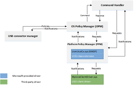
UCSI ACPI Interface
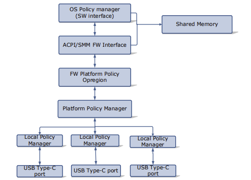
Shared Mailbox Interface
The following table is the reserved memory structure that must be reserved and shared with the EC for communication. When using FF-A this memory region must be statically carved out and 4K aligned and directly accessible by secure world.
| Offset (Bytes) | Mnemonic | Description | Direction | Size (bits) |
|---|---|---|---|---|
| 0 | VERSION | UCSI Version Number | PPM->OPM | 16 |
| 2 | RESERVED | Reserved | N/A | 16 |
| 4 | CCI | USB Type-C Command Status and Connector Change Indication | PPM->OPM | 32 |
| 8 | CONTROL | USB Type-C Control | OPM->PPM | 64 |
| 16 | MESSAGE IN | USB Type-C Message In | PPM->OPM | 128 |
| 32 | MESSAGE OUT | USB Type-C Message Out | OPM->PPM | 128 |
ACPI Definitions
Device(USBC) {
Name(_HID,EISAID(“USBC000”))
Name(_CID,EISAID(“PNP0CA0”))
Name(_UID,1)
Name(_DDN, “USB Type-C”)
Name(_ADR,0x0)
OperationRegion(USBC, SystemMemory, 0xFFFF0000, 0x30)
Field(USBC,AnyAcc,Lock,Preserve)
{
// USB C Mailbox Interface
VERS,16, // PPM-\>OPM Version
RES, 16, // Reservied
CCI, 32, // PPM-\>OPM CCI Indicator
CTRL,64, // OPM-\>PPM Control Messages
MSGI,128, // OPM-\>PPM Message In
MSGO,128, // PPM-\>OPM Message Out
}
Method(_DSM,4,Serialized,0,UnknownObj, {BuffObj, IntObj,IntObj,PkgObj})
{
// Compare passed in UUID to Supported UUID
If(LEqual(Arg0,ToUUID(“6f8398c2-7ca4-11e4-ad36-631042b5008f”)))
{
// Use FFA to send Notification event down to copy data to EC
If(LEqual(\\_SB.FFA0.AVAL,One)) {
CreateQwordField(BUFF,0,STAT) // Out – Status
CreateField(BUFF,128,128,UUID) // UUID of service
CreateByteField(BUFF,32, CMDD) // In – First byte of command
CreateField(BUFF,288,384,FIFD) // Out – Msg data
// Create USCI Doorbell Event
Store(0x0, CMDD) // UCSI set doorbell
Store(ToUUID("daffd814-6eba-4d8c-8a91-bc9bbf4aa301"), UUID) // UCSI
Store(USBC, FIFD) // Copy output data
Store(Store(BUFF, \_SB_.FFA0.FFAC), BUFF)
If(LEqual(STAT,0x0) ) // Check FF-A successful?
{
Return (FIFD)
}
} // End AVAL
Return(Zero)
} // End UUID
} // End DSM
}
EC Input Management
An EC may have several input devices including LID, Power key, touch and keyboard. HID based devices requiring low latency input, are recommended to be connected directly through a non-secure BUS interface such as I2C or I3C for performance reasons.
LID State
Monitor sensors that indicate lid state. If lid is opened, potentially boot the system. If lid is closed, potentially shut down or hibernate the system.
| ACPI | Description |
|---|---|
| _LID | Get state of LID device for clamshell designs |
ACPI Example for LID notificiation
Assuming that LID is managed by the EC during registration we register for Input Management service for a Virtual ID = 1
Name(_DSD, Package() {
ToUUID("daffd814-6eba-4d8c-8a91-bc9bbf4aa301"), //Device Prop UUID
Package() {
Package(2) {
"arm-arml0002-ffa-ntf-bind",
Package() {
1, // Revision
1, // Count of following packages
Package () {
ToUUID("e3168a99-4a57-4a2b-8c5e-11bcfec73406"), // Input Management UUID
Package () {
0x02, // Cookie for LID
}
},
}
}
}
}) // _DSD()
Method(_DSM, 0x4, NotSerialized)
{
// Arg0 - UUID
// Arg1 - Revision
// Arg2: Function Index
// 0 - Query
// 1 - Notify
// 2 - binding failure
// 3 - infra failure
// Arg3 - Data
//
// Device specific method used to query
// configuration data. See ACPI 5.0 specification
// for further details.
//
If(LEqual(Arg0, Buffer(0x10) {
//
// UUID: {7681541E-8827-4239-8D9D-36BE7FE12542}
//
0x1e, 0x54, 0x81, 0x76, 0x27, 0x88, 0x39, 0x42, 0x8d, 0x9d, 0x36, 0xbe, 0x7f, 0xe1, 0x25, 0x42
}))
{
// Query Function
If(LEqual(Arg2, Zero))
{
Return(Buffer(One) { 0x03 }) // Bitmask Query + Notify
}
// Notify Function
If(LEqual(Arg2, One))
{
// Arg3 - Package {UUID, Cookie}
Local0 = DeRefOf(Index(Arg3,1))
Switch(Local0) {
Case(2) {
Notify(\_SB._LID, 0x80)
}
}
}
}
Return(Buffer(One) { 0x00 })
}
System Wake Event
Ability to wake the system from various external events. This is for more complicated events that aren’t a simple GPIO for LID/Power button that require EC monitoring.
HID descriptor Interface
Communication with EC must have packet sent/received in HID format so the OS HIDClass driver can properly understand requests. At this time HID packets will go over HIDI2C but in future these HID packets could be included over a single interface.
| HID IOCTL | Description |
|---|---|
| IOCTL_HID_GET_DEVICE_DESCRIPTOR | Retrieves the device's HID descriptor |
| IOCTL_HID_GET_DEVICE_ATTRIBUTES | Retrieves a device's attributes in a HID_DEVICE_ATTRIBUTES structure |
| IOCTL_HID_GET_REPORT_DESCRIPTOR | Obtains the report descriptor for the HID device |
| IOCTL_HID_READ_REPORT | Returns a report from the device into a class driver-supplied buffer |
| IOCTL_HID_WRITE_REPORT | Transmits a class driver-supplied report to the device |
| IOCTL_HID_GET_FEATURE | Get capabilities of a feature from the device |
| IOCTL_HID_SET_FEATURE | Set/Enable a specific feature on device |
| IOCTL_HID_GET_INPUT_REPORT | Get input report from HID device if input device |
| IOCTL_HID_SET_OUTPUT_REPORT | Send output HID report to device |
| IOCTL_HID_GET_STRING | Get a specific string from device |
| IOCTL_HID_GET_INDEXED_STRING | Get a string from device based on index |
| IOCTL_HID_SEND_IDLE_NOTIFICATION | Notification to idle device into idle/sleep state |
EC Time Alarm Service
The following sections define the operation and definition of the optional control method-based Time and Alarm device, which provides a hardware independent abstraction and a more robust alternative to the Real Time Clock (RTC)
ACPI specification details are in version 6.5 Chapter 9.
| Command | Description |
|---|---|
| EC_TAS_GET_GCP = 0x1 | Get the capabilities of the time and alarm device |
| EC_TAS_GET_GRT = 0x2 | Get the Real Time |
| EC_TAS_SET_SRT = 0x3 | Set the Real Time |
| EC_TAS_GET_GWS = 0x4 | Get Wake Status |
| EC_TAS_SET_CWS = 0x5 | Clear Wake Status |
| EC_TAS_SET_STV = 0x6 | Set Timer value for given timer |
| EC_TAS_GET_TIV = 0x7 | Get Timer value remaining for given timer |
EC_TAS_GET_GCP
This object is required and provides the OSPM with a bit mask of the device capabilities.
9. ACPI-Defined Devices and Device-Specific Objects — ACPI Specification 6.5 documentation
Input Parameters
Input parameters as described in ACPI specification.
Output Parameters
Should return structure as defined by ACPI specification
FFA ACPI
Method (_GCP) {
// Check to make sure FFA is available and not unloaded
If(LEqual(\\_SB.FFA0.AVAL,One)) {
CreateQwordField(BUFF,0,STAT) // Out – Status for req/rsp
CreateField(BUFF,128,128,UUID) // UUID of service
CreateByteField(BUFF,32, CMDD) // In – First byte of command
CreateDwordField(BUFF,32,GCPD) // Out – 32-bit integer described above
Store(0x1, CMDD) // EC_TAS_GET_GCP
Store(ToUUID("23ea63ed-b593-46ea-b027-8924df88e92f"), UUID) // RTC
Store(Store(BUFF, \_SB_.FFA0.FFAC), BUFF)
If(LEqual(STAT,0x0) ) // Check FF-A successful?
{
Return (GCDD)
}
}
Return(Zero)
}
EC_TAS_GET_GRT
This object is required if the capabilities bit 2 is set to 1. The OSPM can use this object to get time. The return value is a buffer containing the time information as described below.
9. ACPI-Defined Devices and Device-Specific Objects — ACPI Specification 6.5 documentation
Input Parameters
Input parameters as described in ACPI specification.
Output Parameters
Should return structure as defined by ACPI specification
FFA ACPI Example
Method (_GRT) {
// Check to make sure FFA is available and not unloaded
If(LEqual(\\_SB.FFA0.AVAL,One)) {
CreateQwordField(BUFF,0,STAT) // Out – Status for req/rsp
CreateField(BUFF,128,128,UUID) // UUID of service
CreateByteField(BUFF,32, CMDD) // In – First byte of command
CreateWordField(BUFF,32,GRT0) // Out Year
CreateByteField(BUFF,36,GRT1) // Out Month
CreateByteField(BUFF,37,GRT2) // Out Day
CreateByteField(BUFF,38,GRT3) // Out Hour
CreateByteField(BUFF,39,GRT4) // Out Minute
CreateByteField(BUFF,40,GRT5) // Out Second
CreateByteField(BUFF,41,GRT6) // Out Valid
CreateWordField(BUFF,42,GRT7) // Out milliseconds
CreateWordField(BUFF,44,GRT8) // Out Timezone
CreateByteField(BUFF,46,GRT9) // Out Daylight
CreateField(BUFF,376,24,PAD0) // Out 3 bytes padding
Store(0x2, CMDD) // EC_TAS_GET_GRT
Store(ToUUID("23ea63ed-b593-46ea-b027-8924df88e92f"), UUID) // RTC
Store(Store(BUFF, \_SB_.FFA0.FFAC), BUFF)
If(LEqual(STAT,0x0) ) // Check FF-A successful?
{
Return (Package() {GRT0,GRT1,GRT2,GRT3,GRT4,GRT5,GRT6,GRT7,GRT8,GRT9, PAD0})
}
}
Return(Package() {0,0,0,0,0,0,0,0,0,0,Buffer(){0,0,0}})
}
EC_TAS_SET_SRT
This object is required if the capabilities bit 2 is set to 1. The OSPM can use this object to set the time.
9. ACPI-Defined Devices and Device-Specific Objects — ACPI Specification 6.5 documentation
Input Parameters
Input parameters as described in ACPI specification.
Output Parameters
Should return structure as defined by ACPI specification
FFA ACPI Example
Method (_SRT) {
// Check to make sure FFA is available and not unloaded
If(LEqual(\\_SB.FFA0.AVAL,One)) {
CreateQwordField(BUFF,0,STAT) // Out – Status for req/rsp
CreateField(BUFF,128,128,UUID) // UUID of service
CreateByteField(BUFF,32, CMDD) // In – First byte of command
CreateField(BUFF,264,128,SRTD) // 16 bytes of data
Store(0x3, CMDD) // EC_TAS_SET_SRT
Store(ToUUID("23ea63ed-b593-46ea-b027-8924df88e92f"), UUID) // RTC
Store(Arg0, SRTD) // Copy over the RTC data
Store(Store(BUFF, \_SB_.FFA0.FFAC), BUFF)
If(LEqual(STAT,0x0) ) // Check FF-A successful?
{
Return (One)
}
}
Return(Zero)}
}
EC_TAS_GET_GWS
This object is required if the capabilities bit 0 is set to 1. It enables the OSPM to read the status of wake alarms
9. ACPI-Defined Devices and Device-Specific Objects — ACPI Specification 6.5 documentation
Input Parameters
Input parameters as described in ACPI specification.
Output Parameters
Should return structure as defined by ACPI specification
FFA ACPI Example
Method (_GWS) {
// Check to make sure FFA is available and not unloaded
If(LEqual(\\_SB.FFA0.AVAL,One)) {
CreateQwordField(BUFF,0,STAT) // Out – Status for req/rsp
CreateField(BUFF,128,128,UUID) // UUID of service
CreateByteField(BUFF,32, CMDD) // In – First byte of command
CreateDwordField(BUFF,33,GWS1) // In – Dword for timer type AC/DC
CreateDwordField(BUFF,32,GWSD) // Out – Dword timer state
Store(20, LENG)
Store(0x4, CMDD) // EC_TAS_GET_GWS
Store(Arg0, GWS1)
Store(ToUUID("23ea63ed-b593-46ea-b027-8924df88e92f"), UUID) // RTC
Store(Store(BUFF, \_SB_.FFA0.FFAC), BUFF)
If(LEqual(STAT,0x0) ) // Check FF-A successful?
{
Return (GWSD)
}
}
Return(Zero)
}
EC_TAS_SET_CWS
This object is required if the capabilities bit 0 is set to 1. It enables the OSPM to clear the status of wake alarms
9. ACPI-Defined Devices and Device-Specific Objects — ACPI Specification 6.5 documentation
Input Parameters
Input parameters as described in ACPI specification.
Output Parameters
Should return structure as defined by ACPI specification
FFA ACPI Example
Method (_CWS) {
// Check to make sure FFA is available and not unloaded
If(LEqual(\\_SB.FFA0.AVAL,One)) {
CreateQwordField(BUFF,0,STAT) // Out – Status for req/rsp
CreateField(BUFF,128,128,UUID) // UUID of service
CreateByteField(BUFF,32, CMDD) // In – First byte of command
CreateDwordField(BUFF,33, CWS1) // In – Dword for timer type AC/DC
CreateDwordField(BUFF,32,CWSD) // Out – Dword timer state
Store(20, LENG)
Store(0x5, CMDD) // EC_TAS_SET_CWS
Store(Arg0,CWS1)
Store(ToUUID("23ea63ed-b593-46ea-b027-8924df88e92f"), UUID) // RTC
Store(Store(BUFF, \_SB_.FFA0.FFAC), BUFF)
If(LEqual(STAT,0x0) ) // Check FF-A successful?
{
Return (CWSD)
}
}
Return(Zero)
}
EC_TAS_SET_STV
This object is required if the capabilities bit 0 is set to 1. It sets the timer to the specified value.
9. ACPI-Defined Devices and Device-Specific Objects — ACPI Specification 6.5 documentation
Input Parameters
Input parameters as described in ACPI specification.
Output Parameters
Should return structure as defined by ACPI specification
FFA ACPI Example
Method (_STV) {
// Check to make sure FFA is available and not unloaded
If(LEqual(\\_SB.FFA0.AVAL,One)) {
CreateQwordField(BUFF,0,STAT) // Out – Status for req/rsp
CreateField(BUFF,128,128,UUID) // UUID of service
CreateByteField(BUFF,32, CMDD) // In – First byte of command
CreateDwordField(BUFF,33, STV1) // In – Dword for timer type AC/DC
CreateDwordField(BUFF,37, STV2) // In – Dword Timer Value
CreateDwordField(BUFF,2,STVD) // Out – Dword timer state
Store(0x6, CMDD) // EC_TAS_SET_STV
Store(Arg0,STV1)
Store(Arg1,STV2)
Store(ToUUID("23ea63ed-b593-46ea-b027-8924df88e92f"), UUID) // RTC
Store(Store(BUFF, \_SB_.FFA0.FFAC), BUFF)
If(LEqual(STAT,0x0) ) // Check FF-A successful?
{
Return (STVD)
}
}
Return(Zero)
}
EC_TAS_GET_TIV
This object is required if the capabilities bit 0 is set to 1. It returns the remaining time of the specified timer before that expires.
9. ACPI-Defined Devices and Device-Specific Objects — ACPI Specification 6.5 documentation
Input Parameters
Input parameters as described in ACPI specification.
Output Parameters
Should return structure as defined by ACPI specification
FFA ACPI Example
Method (_TIV) {
// Check to make sure FFA is available and not unloaded
If(LEqual(\\_SB.FFA0.AVAL,One)) {
CreateQwordField(BUFF,0,STAT) // Out – Status for req/rsp
CreateField(BUFF,128,128,UUID) // UUID of service
CreateByteField(BUFF,32, CMDD) // In – First byte of command
CreateDwordField(BUFF,33, TIV1) // In – Dword for timer type AC/DC
CreateDwordField(BUFF,32,TIVD) // Out – Dword timer state
Store(0x7, CMDD) // EC_TAS_GET_TIV
Store(Arg0,TIV1)
Store(ToUUID("23ea63ed-b593-46ea-b027-8924df88e92f"), UUID) // RTC
Store(Store(BUFF, \_SB_.FFA0.FFAC), BUFF)
If(LEqual(STAT,0x0) ) // Check FF-A successful?
{
Return (TIVD)
}
}
Return(Zero)
}
EC Debug Service
The debug service is used for telemetry, debug logs, system reset information etc.
Recovery Mode
Put EC into recovery mode for development flashing and debugging.
Dump Debug State
EC should be able to support typical engineering requests, such as getting detailed subsystem information, setting/getting GPIOs, etc, for design verification and benchtop testing.
Telemetry
Ability to communicate with the HLOS event logging system, and record EC critical events for later analysis.
System Boot State
In many designs, OEMs will desire indication that the system is responding to a power on request. This could be a logo display on the screen or a bezel LED. EC should be able to control these devices during the boot sequence.
During first boot sequence EC may also be initialized and setup its services. Needs to know when OS is up to send notification for events that are only used by OS.
Memory Mapped Transactions
There are two cases where you may want to use the memory mapped transactions. The first is if you have a large buffer you need to transfer data between EC and HLOS like a debug buffer. The second use case is if you want to emulate an eSPI memory mapped interface for compatibility with legacy devices.
For this mode to work you will need memory carved out which is dedicated and shared between HLOS and secure world. In your UEFI memory map this memory should be marked as EfiMemoryReservedType so that the OS will not use or allocate the memory. In your SP manifest file you will also need to add access to this physical memory range. It needs to be aligned on a 4K boundary and a multiple of 4K. This memory region is carved out and must never be used for any other purpose. Since the memory is shared with HLOS there is also no security surrounding accesses to the memory.
Example Memory Mapped Interface
// Map 4K memory region shared
OperationRegion(ABCD, SystemMemory, 0xFFFF0000, 0x1000)
// DSM Method to send sync event
Method(_DSM,4,Serialized,0,UnknownObj, {BuffObj, IntObj,IntObj,PkgObj})
{
// Compare passed in UUID to Supported UUID
If(LEqual(Arg0,ToUUID(“6f8398c2-7ca4-11e4-ad36-631042b5008f”)))
{
// Use FFA to send Notification event down to copy data to EC
If(LEqual(\\_SB.FFA0.AVAL,One)) {
CreateQwordField(BUFF,0,STAT) // Out – Status for req/rsp
CreateField(BUFF,128,128,UUID) // UUID of service
CreateByteField(BUFF,32, CMDD) // In – First byte of command
// Create Doorbell Event to read shared memory
Store(0x0, CMDD) //
Store(ToUUID("daffd814-6eba-4d8c-8a91-bc9bbf4aa301"), UUID) // Debug Service UUID
Store(Store(BUFF, \_SB_.FFA0.FFAC), BUFF)
} // End AVAL
} // End UUID
} // End DSM
Any updates from the EC come back through a notification event registered in the FFA for this particular service.
EC Manufacturing Service
This service should contain all the functionality that is need to perform self test, validation of the EC and special manufacturing modes. This service should be disabled on retail devices or at least protected to prevent unwanted modes.
Self Test
EC should perform self test and return results/details of test validation
Set Calibration Data
Have ability to store factory calibrations and setup information into EC non-volatile memory. For instance keyboard language information, or thermistor calibration values.
EC OEM Service
Any OEM special custom features should be put in their own service sandbox to support OEM specific features. This will prevent definitions from colliding with other services.
Sample System Implementation
ACPI Interface Definition
FFA Device Definition
Device(\_SB_.FFA0) {
Name(_HID, "MSFT000C")
OperationRegion(AFFH, FFixedHw, 4, 144)
Field(AFFH, BufferAcc, NoLock, Preserve) { AccessAs(BufferAcc, 0x1), FFAC, 1152 }
// Other components check this to make sure FFA is available
Method(AVAL, 0, Serialized) {
Return(One)
}
// Register notification events from FFA
Method(_RNY, 0, Serialized) {
Return( Package() {
Package(0x2) { // Events for Management Service
ToUUID("330c1273-fde5-4757-9819-5b6539037502"),
Buffer() {0x1,0x0} // Register event 0x1
},
Package(0x2) { // Events for Thermal service
ToUUID("31f56da7-593c-4d72-a4b3-8fc7171ac073"),
Buffer() {0x1,0x0,0x2,0x0,0x3,0x0} // Register events 0x1, 0x2, 0x3
},
Package(0x2) { // Events for input device
ToUUID("e3168a99-4a57-4a2b-8c5e-11bcfec73406"),
Buffer() {0x1,0x0} // Register event 0x1 for LID
}
} )
}
Method(_NFY, 2, Serialized) {
// Arg0 == UUID
// Arg1 == Notify ID
// Management Service Events
If(LEqual(ToUUID("330c1273-fde5-4757-9819-5b6539037502"),Arg0)) {
Switch(Arg1) {
Case(1) { // Test Notification Event
Notify(\_SB.ECT0,0x20)
}
}
}
// Thermal service events
If(LEqual(ToUUID("31f56da7-593c-4d72-a4b3-8fc7171ac073"),Arg0)) {
Switch(Arg1) {
Case(1) { // Temp crossed low threshold
Notify(\_SB.SKIN,0x80)
}
Case(2) { // Temp crossed high threshold
Notify(\_SB.SKIN,0x81)
}
Case(3) { // Critical temperature event
Notify(\_SB.SKIN,0x82)
}
}
}
// Input Device Events
If(LEqual(ToUUID("e3168a99-4a57-4a2b-8c5e-11bcfec73406"),Arg0)) {
Switch(Arg1) {
Case(1) { // LID event
Notify(\_SB._LID,0x80)
}
}
}
}
}
Memory Mapped Interface via FFA for UCSI
Note for this implementation of memory mapped interface to work the memory must be marked as reserved by UEFI and not used by the OS and direct access also given to the corresponding service in secure world.
Device(USBC) {
Name(_HID,EISAID(“USBC000”))
Name(_CID,EISAID(“PNP0CA0”))
Name(_UID,1)
Name(_DDN, “USB Type-C”)
Name(_ADR,0x0)
Name(BUFF, Buffer(144){}) // Create buffer for FFA data
OperationRegion(USBC, SystemMemory, UCSI_PHYS_MEM, 0x30)
Field(USBC,AnyAcc,Lock,Preserve)
{
// USB C Mailbox Interface
VERS,16, // PPM-\>OPM Version
RES, 16, // Reservied
CCI, 32, // PPM-\>OPM CCI Indicator
CTRL,64, // OPM-\>PPM Control Messages
MSGI,128, // OPM-\>PPM Message In
MSGO,128, // PPM-\>OPM Message Out
}
Method(_DSM,4,Serialized,0,UnknownObj, {BuffObj, IntObj,IntObj,PkgObj})
{
// Compare passed in UUID to Supported UUID
If(LEqual(Arg0,ToUUID(“6f8398c2-7ca4-11e4-ad36-631042b5008f”)))
{
// Use FFA to send Notification event down to copy data to EC
If(LEqual(\_SB.FFA0.AVAL,One)) {
CreateQwordField(BUFF,0,STAT) // Out – Status for req/rsp
CreateField(BUFF,128,128,UUID) // UUID of service
CreateByteField(BUFF,32, CMDD) // In – First byte of command
CreateField(BUFF,288,384,FIFD) // Out – Msg data
// Create Doorbell Event
Store(0x0, CMDD) // UCSI set doorbell
Store(ToUUID("daffd814-6eba-4d8c-8a91-bc9bbf4aa301"), UUID)
Store(USBC,FIFD)
Store(Store(BUFF, \_SB_.FFA0.FFAC), BUFF)
} // End AVAL
} // End UUID
} // End DSM
}
Thermal ACPI Interface for FFA
This sample code shows one Microsoft Thermal zone for SKIN and then a thermal device THRM for implementing customized IO.
// Sample Definition of FAN ACPI
Device(SKIN) {
Name(_HID, "MSFT000A")
Method(_TMP, 0x0, Serialized) {
If(LEqual(\_SB.FFA0.AVAL,One)) {
CreateQwordField(BUFF,0,STAT) // Out – Status for req/rsp
CreateField(BUFF,128,128,UUID) // UUID of service
CreateByteField(BUFF,32,CMDD) // Command register
CreateByteField(BUFF,33,TZID) // Temp Sensor ID
CreateDWordField(BUFF,32,RTMP) // Output Data
Store(0x1, CMDD) // EC_THM_GET_TMP
Store(0x2, TZID) // Temp zone ID for SKIIN
Store(ToUUID("31f56da7-593c-4d72-a4b3-8fc7171ac073"), UUID)
Store(Store(BUFF, \_SB_.FFA0.FFAC), BUFF)
If(LEqual(STAT,0x0) ) // Check FF-A successful?
{
Return (RTMP)
}
}
Return (Ones)
}
// Arg0 Temp sensor ID
// Arg1 Package with Low and High set points
Method(THRS,0x2, Serialized) {
If(LEqual(\_SB.FFA0.AVAL,One)) {
CreateQwordField(BUFF,0,STAT) // Out – Status for req/rsp
CreateField(BUFF,128,128,UUID) // UUID of service
CreateByteField(BUFF,32,CMDD) // Command register
CreateByteField(BUFF,33,TZID) // Temp Sensor ID
CreateDwordField(BUFF,34,VTIM) // Timeout
CreateDwordField(BUFF,38,VLO) // Low Threshold
CreateDwordField(BUFF,42,VHI) // High Threshold
CreateDWordField(BUFF,46,TSTS) // Output Data
Store(ToUUID("31f56da7-593c-4d72-a4b3-8fc7171ac073"), UUID)
Store(0x2, CMDD) // EC_THM_SET_THRS
Store(Arg0, TZID)
Store(DeRefOf(Index(Arg1,0)),VTIM)
Store(DeRefOf(Index(Arg1,1)),VLO)
Store(DeRefOf(Index(Arg1,2)),VHI)
Store(Store(BUFF, \_SB_.FFA0.FFAC), BUFF)
If(LEqual(STAT,0x0) ) // Check FF-A successful?
{
Return (TSTS)
}
}
Return (0x3) // Hardware failure
}
// Arg0 GUID 1f0849fc-a845-4fcf-865c-4101bf8e8d79
// Arg1 Revision
// Arg2 Function Index
// Arg3 Function dependent
Method(_DSM, 0x4, Serialized) {
If(LEqual(ToUuid("1f0849fc-a845-4fcf-865c-4101bf8e8d79"),Arg0)) {
Switch(Arg2) {
Case (0) {
Return(0x3) // Support Function 0 and Function 1
}
Case (1) {
Return( THRS(0x2, Arg3) ) // Call to function to set threshold
}
}
}
Return(0x3)
}
}
Device(THRM) {
Name(_HID, "MSFT000B")
// Arg0 Instance ID
// Arg1 UUID of variable
// Return (Status,Value)
Method(GVAR,2,Serialized) {
If(LEqual(\_SB.FFA0.AVAL,One)) {
CreateQwordField(BUFF,0,STAT) // Out – Status for req/rsp
CreateField(BUFF,128,128,UUID) // UUID of service
CreateByteField(BUFF,32,CMDD) // Command register
CreateByteField(BUFF,33,INST) // Instance ID
CreateWordField(BUFF,34,VLEN) // 16-bit variable length
CreateField(BUFF,288,128,VUID) // UUID of variable to read
CreateQwordField(BUFF,52,64,RVAL) // Output Data
Store(ToUUID("31f56da7-593c-4d72-a4b3-8fc7171ac073"), UUID)
Store(0x5, CMDD) // EC_THM_GET_VAR
Store(Arg0,INST) // Save instance ID
Store(4,VLEN) // Variable is always DWORD here
Store(Arg1, VUID)
Store(Store(BUFF, \_SB_.FFA0.FFAC), BUFF)
If(LEqual(STAT,0x0) ) // Check FF-A successful?
{
Return (RVAL)
}
}
Return (0x3)
}
// Arg0 Instance ID
// Arg1 UUID of variable
// Return (Status,Value)
Method(SVAR,3,Serialized) {
If(LEqual(\_SB.FFA0.AVAL,One)) {
CreateQwordField(BUFF,0,STAT) // Out – Status for req/rsp
CreateField(BUFF,128,128,UUID) // UUID of service
CreateByteField(BUFF,32,CMDD) // Command register
CreateByteField(BUFF,33,INST) // Instance ID
CreateWordField(BUFF,34,VLEN) // 16-bit variable length
CreateField(BUFF,288,128,VUID) // UUID of variable to Write
CreateQwordField(BUFF,52,64,RVAL) // Output Data
CreateDwordField(BUFF,60,DVAL) // Data value
Store(ToUUID("31f56da7-593c-4d72-a4b3-8fc7171ac073"), UUID)
Store(0x6, CMDD) // EC_THM_SET_VAR
Store(Arg0,INST) // Save instance ID
Store(4,VLEN) // Variable is always DWORD here
Store(Arg1, VUID)
Store(Arg2,DVAL)
Store(Store(BUFF, \_SB_.FFA0.FFAC), BUFF)
If(LEqual(STAT,0x0) ) // Check FF-A successful?
{
Return (RVAL)
}
}
Return (0x3)
}
// Arg0 GUID
// 07ff6382-e29a-47c9-ac87-e79dad71dd82 - Input
// d9b9b7f3-2a3e-4064-8841-cb13d317669e - Output
// Arg1 Revision
// Arg2 Function Index
// Arg3 Function dependent
Method(_DSM, 0x4, Serialized) {
// Input Variable
If(LEqual(ToUuid("07ff6382-e29a-47c9-ac87-e79dad71dd82"),Arg0)) {
Switch(Arg2) {
Case(0) {
// We support function 0-3
Return(0xf)
}
Case(1) {
Return(GVAR(1,ToUuid("ba17b567-c368-48d5-bc6f-a312a41583c1"))) // OnTemp
}
Case(2) {
Return(GVAR(1,ToUuid("3a62688c-d95b-4d2d-bacc-90d7a5816bcd"))) // RampTemp
}
Case(3) {
Return(GVAR(1,ToUuid("dcb758b1-f0fd-4ec7-b2c0-ef1e2a547b76"))) // MaxTemp
}
}
Return(0x1)
}
// Output Variable
If(LEqual(ToUuid("d9b9b7f3-2a3e-4064-8841-cb13d317669e"),Arg0)) {
Switch(Arg2) {
Case(0) {
// We support function 0-3
Return(0xf)
}
Case(1) {
Return(SVAR(1,ToUuid("ba17b567-c368-48d5-bc6f-a312a41583c1"),Arg3)) // OnTemp
}
Case(2) {
Return(SVAR(1,ToUuid("3a62688c-d95b-4d2d-bacc-90d7a5816bcd"),Arg3)) // RampTemp
}
Case(3) {
Return(SVAR(1,ToUuid("dcb758b1-f0fd-4ec7-b2c0-ef1e2a547b76"),Arg3)) // MaxTemp
}
}
}
Return (0x1)
}
}
Call Flows for secure and non-secure Implementation
Depending on system requirements the ACPI calls may go directly to the EC or through secure world then through to EC.
When using non-secure interface the ACPI functions must define protocol level which is the Embedded controller for eSPI. For I2C/I3C or SPI interfaces the corresponding ACPI device must define the bus dependency and build the packet directly that is sent to the EC.
For secure communication all data is sent to the secure world via FF-A commands described in this document and the actual bus protocol and data sent to the EC is defined in the secure world in Hafnium. All support for FF-A is inboxed in the OS by default so EC communication will always work in any environment. However, FF-A is not supported in x86/x64 platforms so direct EC communication must be used on these platforms.
Non-Secure eSPI Access
This call flow assumes using Embedded controller definition with independent ACPI functions for MPTF support
Non-Secure eSPI READ
Device(EC0) {
Name(_HID, EISAID("PNP0C09")) // ID for this EC
// current resource description for this EC
Name(_CRS, ResourceTemplate() {
Memory32Fixed (ReadWrite, 0x100000, 0x10) // Used for simulated port access
Memory32Fixed (ReadWrite, 0x100010, 0x10)
// Interrupt defined for eSPI event signalling
GpioInt(Edge, ActiveHigh, ExclusiveAndWake,PullUp 0,"\_SB.GPI2"){43}
})
Name(_GPE, 0) // GPE index for this EC
// create EC's region and field for thermal support
OperationRegion(EC0, EmbeddedControl, 0, 0xFF)
Field(EC0, ByteAcc, Lock, Preserve) {
MODE, 1, // thermal policy (quiet/perform)
FAN, 1, // fan power (on/off)
, 6, // reserved
TMP, 16, // current temp
AC0, 16, // active cooling temp (fan high)
, 16, // reserved
PSV, 16, // passive cooling temp
HOT 16, // critical S4 temp
CRT, 16 // critical temp
BST1, 32, // Battery State
BST2, 32, // Battery Present Rate
BST3, 32, // Battery Remaining capacity
BST4, 32, // Battery Present Voltage
}
Method (_BST) {
Name (BSTD, Package (0x4)
{
\_SB.PCI0.ISA0.EC0.BST1, // Battery State
\_SB.PCI0.ISA0.EC0.BST2, // Battery Present Rate
\_SB.PCI0.ISA0.EC0.BST3, // Battery Remaining Capacity
\_SB.PCI0.ISA0.EC0.BST4, // Battery Present Voltage
})
Return(BSTD)
}
}
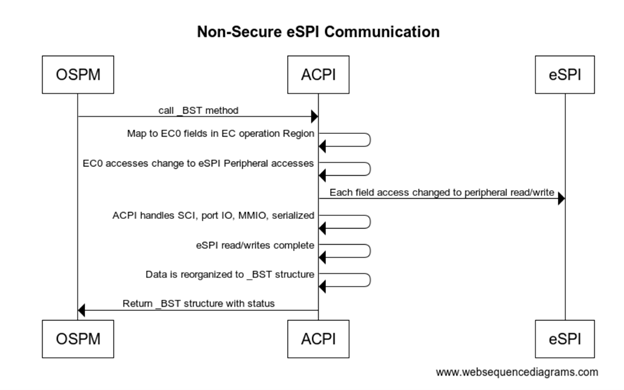
Non-Secure eSPI Notifications
All interrupts are handled by the ACPI driver. When EC needs to send a notification event the GPIO is asserted and traps into IRQ. ACPI driver reads the EC_SC status register to determine if an SCI is pending. DPC callback calls and reads the EC_DATA port to determine the _Qxx event that is pending. Based on the event that is determined by ACPI the corresponding _Qxx event function is called.
Method (_Q07) {
// Take action for event 7
Notify(\_SB._LID, 0x80)
}
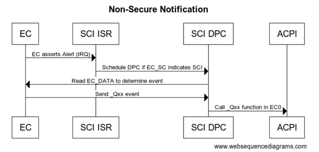
Secure eSPI Access
The following flow assumes ARM platform using FF-A for secure calls. Note if you want to use the same EC firmware on both platforms with secure and non-secure access the EC_BAT_GET_BST in this case should be convert to a peripheral access with the same IO port and offset as non-secure definition.
Secure eSPI READ
Method (_BST, 0, Serialized) {
// Check to make sure FFA is available and not unloaded
If(LEqual(\_SB.FFA0.AVAL,One)) {
CreateDwordField(BUFF,0,STAT) // Out – Status for req/rsp
CreateField(BUFF,128,128,UUID) // UUID of service
CreateByteField(BUFF,32,CMDD) // In – First byte of command
CreateDwordField(BUFF,32,BST0) // Out – Battery State DWord
CreateDwordField(BUFF,36,BST1) // Out – Battery Rate DWord
CreateDwordField(BUFF,40,BST2) // Out – Battery Reamining Capacity DWord
CreateDwordField(BUFF,44,BST3) // Out – Battery Voltage DWord
Store(0x2, CMDD) //EC_BAT_GET_BST
Store(ToUUID("25cb5207-ac36-427d-aaef-3aa78877d27e"), UUID)
Store(Store(BUFF, \_SB_.FFA0.FFAC), BUFF)
If(LEqual(STAT,0x0) ) // Check FF-A successful?
{
return(Package() {BST0, BST1, BST2, BST3} )
}
}
Return(Package() {0,0,0,0})
}
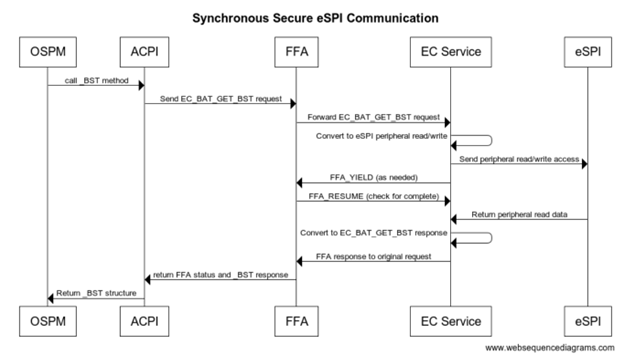
Secure eSPI Notification
When EC communication is done through Secure world we assert FIQ which is handled as eSPI interrupt. eSPI driver reads EC_SC and EC_DATA to retrieve the notification event details. On Non-secure implementation ACPI converts this to Qxx callback. On secure platform this is converted to a virtual ID and sent back to the OS via _NFY callback and a virtual ID.
Method(_DSM, 0x4, NotSerialized)
{
// Arg0 - UUID
// Arg1 - Revision
// Arg2: Function Index
// 0 - Query
// 1 - Notify
// 2 - binding failure
// 3 - infra failure
// Arg3 - Data
//
// Device specific method used to query
// configuration data. See ACPI 5.0 specification
// for further details.
//
If(LEqual(Arg0, Buffer(0x10) {
//
// UUID: {7681541E-8827-4239-8D9D-36BE7FE12542}
//
0x1e, 0x54, 0x81, 0x76, 0x27, 0x88, 0x39, 0x42, 0x8d, 0x9d, 0x36, 0xbe, 0x7f, 0xe1, 0x25, 0x42
}))
{
// Query Function
If(LEqual(Arg2, Zero))
{
Return(Buffer(One) { 0x03 }) // Bitmask Query + Notify
}
// Notify Function
If(LEqual(Arg2, One))
{
// Arg3 - Package {UUID, Cookie}
Store(DeRefOf(Index(Arg3,1)), \_SB.ECT0.NEVT )
If(LEqual(0x2,\_SB.ECT0.NEVT)) {
Notify(\_SB._LID, 0x80)
}
}
}
Return(Buffer(One) { 0x00 })
}