Open Device Partnership documentation guide
The purpose of this document is to guide you through an understanding of ODP regardless of where you are starting from or where your interest may lie.
The overall ODP umbrella is quite large and encompassing, and can be tricky to navigate through, so we will try to simplify that journey a little as well as giving direction on which path along the journey might best fit your interest or involvement.
This document will briefly review the value proposition of ODP and why it is the right technology for the future of firmware development, at the right time.
Then the different ‘tracks’ of ODP will be explained. Here, you may find you are interested in only one of these tracks, or you may find you want to learn more about all of them.
Then, what is inside ODP and where to find it is detailed further - this is a good resource for those simply wishing to navigate the maze of contributed repositories that are available and which ones fit together for a given task.
Patina (boot firmware) documentation is covered conceptually in this guide. Developers wishing to dig into code examples for this aspect of ODP should follow the resources outlined in the Patina Track.
Finally, for developers wishing to know more about how all of this comes together for an Embedded Controller, a series of example implementation exercises are detailed. These exercises can be explored per-component, or as a series that culminates in a working integration with a simulation application and test.
You are in control of how you navigate through this guide, whether you proceed through it all one step at a time, or jump into the paths you find most compelling to your interest is entirely up to you.
Why ODP?
Modern computing devices are ubiquitous in our current time. They are integral to multiple aspects of our lives, from our workplace, to our finances, our creative endeavors, and our personal lifestyles.
Computer technology seemingly leapt from its cradle a half century ago and never slowed its pace. It is easy to take much of it for granted.
We marvel as the new applications show us increasingly amazing opportunities. We also recognize and guard against the threats these applications pose to ourselves and society.
And in this heady environment, it is sometimes easy to forget that the “hidden parts” of these computers we use – the lower-level hardware and firmware – is often built upon languages and processes that, although having evolved to meet the demands of the time, are reaching the end of their practical sustainability for keeping up with the accelerating pace of the world around us.
What was originally just a “boot layer” and a few K of code for key hardware interfacing is now shouldering the responsibility of securing personal information and behavior patterns that a malicious intruder could use for nefarious purposes.
High-value proprietary algorithms and Artificial Intelligence models are now built into the firmware and must be locked down. An increasing number of “always ready” peripherals, such as the battery and charger, biometric identification mechanisms, network connections, and other concerns are being increasingly handled by independent MCUs that must coordinate with one another and with the host system in a responsive, increasingly complex, yet highly secure manner.
Trying to manage all of this with what has been the status-quo for these concerns in past decades, without memory-safe languages and with a loosely-federated collection of standards and patterns agreed upon by an ad-hoc consortium of vendors is increasingly dangerous and costly.
| Legacy Approach | ODP Approach |
|---|---|
| 🐜 Many vendor-specific changesets ❌ | 🧩 Cross-platform modularity 🔒 |
| ❄️ Weak component isolation 🩸 | 🔐 Secure runtime services 🤖 |
| 🔩 Proprietary tool building ⚔️ | 🛠️ Rust-based build tools, Stuart 🧑🔧 |
The firmware we once almost ignored is now the front line of platform security
The Open Device Partnership offers an alternative and a way forward to a more sustainable future that, while still built upon the proven paradigms of the past, boldly rejects the patterns that are known to be costly and ineffective in favor of future-ready, portable, sustainable, and expandable alternatives.
Key to this is the adoption of the programming language Rust as the successor to C. This immediately brings greater confidence that the code will not be susceptible to programming-error related vulnerabilities that may lead to either costly performance behaviors or be maliciously exploited by opportunistic bad actors. Code may be marked unsafe to allow certain difficult-to-static-analyze behaviors that can be asserted to be risk-free, so potentially dangerous area must be carefully justified. Furthermore, the patterns adopted by ODP provides the confidence that code from outside of one’s immediate provenance of control may be audited and trusted and ready to join into a firmware construction built upon industry standards.
In the pages ahead, we’ll look a little more closely at the advantages of ODP one at a time.
Security
Reduce firmware attack surface significantly, and meet modern security expectations using proven tools and patterns.
Security and Trustworthiness from the Ground Up
“If the foundation is weak, nothing built on top can be trusted.”
Rust is a modern, memory-safe language that mitigates entire classes of vulnerabilities endemic to C memory management, buffer overflows, use-after-free, and so forth by detecting and addressing these issues at compile time – so there are few, if any, unpleasant surprises at runtime.
ODP is foundationally centered around Rust and not only embraces these philosophies, it defines patterns that further enhance the memory-safe paradigm, by preventing unauthorized access between ownership domains and guarding against possible malicious intrusions while implementing proven industry-standard patterns.
flowchart LR
  Start[Power On] --> ROM
  ROM --> FirmwareCheck[Validate Firmware Signature]
  FirmwareCheck --> DXECore[Load DXE Core]
  DXECore --> OSLoader[Invoke Bootloader]
  OSLoader --> OSVerify[Validate OS Signature]
  OSVerify --> OSBoot[Launch OS]
  OSBoot --> Ready[Platform Ready]
Adoption of standards and patterns of DICE and EL2 Hypervisor supported architectures – from a Rust-driven baseline - enables a hardware-rooted chain of trust across boot phases, aligning with NIST and platform security goals and requirements.
ODP makes component modularity and portability with a transparent provenance a practical and safe proposition by making it feasiable to audit and verify firmware behavior in specifically constrained ways.
Modular and Composable Firmware Architecture
ODP offers Modularity and Agility not normally found in the firmware domain.
The buzz and the headlines generated by advances in the computer world typically belong to those who have created magic at the application layer. As such, this portion of the development community has seen exponential advances in the tooling and languages at their disposal. This has provided a high level of modularity and with it, agility, that has become synonymous with the market responsiveness we see in the evolution of our favorite applications.
Firmware development, on the other hand, has generally been mired in the processes of the past, and has not enjoyed this same level of modularity and agility.
“Systems scale better when their parts can evolve independently.”
Composable and portable component modules
ODP changes that paradigm and raises the tide. It is inspired by modern software engineering practices: composability, dependency injection, testability.
Components (e.g., battery service, serial logging, boot policies) are decoupled and swappable, enabling faster iteration and better maintainability.
graph LR
  PowerPolicy --> BatteryService
  PowerPolicy --> ChargerService
  PowerPolicy --> ThermalService
  BatteryService --> BatteryController
  ChargerService --> SMbusDriver
Because Rust enforces its memory and safety management guarantees at compile time, tooling such as that found in ODP Patina for example will build a DXE Core monolithically, without the need for an RTOS, and supports a composed modularity paradigm by design, streamlining certification and troubleshooting.
Cross-Domain Coherence
ODP is not just a patch atop of old layers. It is explicitly aligning system layers to reduce duplication, ambiguity, and failure points.
ODP is not just a firmware stack, but a vision that unites the embedded controller, main firmware, and even secure services under a coherent design and tooling approach.
Common patterns with clearly defined lanes
“Secure systems require secure interfaces — everywhere.”
Shared services and conventions allow clear division of responsibility between firmware, EC, and OS—while promoting reuse and coordination.
graph LR
    Host[Host Domain] --> HostServiceA
  Host --> HostServiceB

  HostServiceA --> HostDriverA
  HostServiceB --> HostDriverB

  EC[Embedded Controller Domain] --> ECServiceA
  EC --> ECServiceB

  subgraph Shared Interface
    HostServiceA <---> ECServiceA
    HostServiceB <---> ECServiceB
  end
Improved Developer Experience
ODP reduces developer friction and increases confidence, thus shortening the time to value for the development effort.
“Firmware development shouldn’t feel like archaeology.”
Developers can build and test components in isolation (e.g., battery, GPIO, boot timer), aided by QEMU emulation, mocks, and test harnesses.
ODP can improve developer engagement and productivity by:
- 🚀 Reducing developer friction
- 🛠️ Supporting tooling that’s approachable and efficient
- 🧪 Enabling fast iteration and confident change
- 💬 Reinforcing that firmware development is not arcane magic, just solid coding.
The Rust ecosystem brings built-in unit testing, logging, dependency control (Cargo), and static analysis.
timeline
  title Developer Workflow Evolution
  2000 : Edit ASM/C, guess BIOS behavior
  2010 : Use UEFI drivers, painful debug cycle
  2023 : Rust-based firmware prototypes emerge
  2024 : ODP introduces modular build + Stuart tools
  2025 : Fully testable DXE + EC code in Rust with shared tooling
flowchart LR
  Idea["💡 Idea"] --> Dev["🧩 Create Service Component"]
  Dev --> Test["🧪 Unit & Desktop Test"]
  Test --> Build["🔧 Cross-target Build<br/>(host & EC)"]
flowchart LR
  Build --> Sim["🖥️ Simulate with Mock Devices"]
  Sim --> Flash["🚀 Build & Flash"]
  Flash --> Log["📄 Review Logs / Debug"]
  Log --> Iterate["🔁 Iterate with Confidence"]
Sustainability and Long-Term Cost Reduction
ODP can help cut tech debt at its root by investing in sustainable design by enabling leaner teams and cleaner codebases.
“Technical debt is financial debt — just hidden in your firmware.”
Build right and reuse
Replacing legacy code with safer, testable, and reusable modules means lower maintenance costs over time.
flowchart LR
  Legacy["Legacy Stack"] --> Duplication["💥 Code Duplication"]
  Legacy --> Debugging["🐛 Opaque Bugs"]
  Legacy --> Porting["🔧 Costly Platform Bring-up"]
  Legacy --> Compliance["⚖️ Expensive Security Reviews"]
  Legacy --> Waste["🗑️ Rewrite Instead of Reuse"]
HAL separation
The ability to reuse and recompose across product lines (via ODP libraries) reduces the need to “reinvent the wheel” for each board/platform, as Hardware Abstraction Layers can be cleanly isolated from the business logic of a component design, and easily expanded upon for new features.
More than HAL
This component philosophy extends much further than replaceable HAL layers – it permeates throughout the component and service structure patterns ODP exposes. This allows agile modularity, greater reuseability, and shorter development cycles.
sequenceDiagram
  participant Dev as Developer
  participant Repo as Shared Component Repo
  participant DeviceA as Platform A
  participant DeviceB as Platform B

  Dev->>Repo: Build & Test Component
  DeviceA->>Repo: Pull Component A
  DeviceB->>Repo: Pull Component A
  Dev->>DeviceA: Customize Config
  Dev->>DeviceB: Customize Config
  Note right of Dev: One codebase, many targets
Alignment with Industry Trends and Standards
ODP is forward-facing from its original concept, and embodied in its design. Adoption of ODP positions you at the forefront of secure, future-facing firmware innovation.
“ODP doesn’t rewrite the rules — it implements them with confidence.”
Perfectly Timed
ODP taps into the growing ecosystem momentum around Rust and embedded standards. Rust adoption at Microsoft, Google, and the Linux kernel reflects a broader industry shift.
Open Source and Collaborative
ODP Encourages upstream contributions and compliance with modern firmware interfaces (UEFI, ACPI, DICE).
An open collaboration model invites cross-vendor reuse and innovation while building upon existing standards known to the industry.
graph TD
  A1[UEFI Spec] --> B1[DXE Core]
  A2[ACPI] --> B2[Runtime Services]
  A3[DICE] --> B3[Secure Boot]
  A4[SPDM] --> B3
  A5[DMTF] --> B4[Mgmt Layer]

  B1 --> C[ODP Framework]
  B2 --> C
  B3 --> C
  B4 --> C
Getting Started with ODP

Welcome to the Open Device Partnership (ODP)!
ODP is a community-driven framework for building secure, modular, and reusable firmware components across a range of systems. Whether you’re interested in low-level boot firmware, embedded controller services, or integrating a complete firmware stack, ODP has something for you.
What is ODP?
ODP brings modern software engineering practices—like memory safety and dependency injection—to the world of firmware. It leverages Rust to improve confidence, maintainability, and modularity across diverse hardware and system designs.
It also embraces existing standards like UEFI, DICE, ACPI, and EC protocols—but makes them more accessible and safer to implement.
How to Use This Guide
This documentation is designed to serve multiple audiences working with the Open Device Partnership (ODP). Whether you’re a firmware engineer, technology advisor, integrator, or contributor, you’ll find resources tailored to your needs.
In the Tracks of ODP, you will find curated content organized into guided paths. Each track is designed to help you learn about ODP from different perspectives, whether you’re focused on value propositions, specific technologies like Patina, or roles such as engineering or advising.
Role-Based Reading Guidance
| Role | Recommended Path |
|---|---|
| Firmware Engineer | Follow the documentation from start to finish. Includes technical tutorials, architectural insights, and integration exercises. |
| Technology Advisor | Read the mainline content up through the Architectural Overview. Skip hands-on exercises. Then proceed to the Tracks page to explore summaries and technical overviews by topic. |
| Integrator | Read through the Architectural Overview and Integration sections, then follow the Integrator Track for platform-specific setup and bundling guidance. |
| Contributor | Review the mainline Value Proposition and Architecture Overview, then head to the Contributor Track for community, contribution standards, and roadmap content. |
| Security Reviewer | Jump to the Security Track. It includes collected topics around trusted boot, isolation, and other security concerns, with cross-links to affected design areas. |
| Patina SDK (UEFI) Developer | Refer to external Patina resources with context provided in the Patina Track. You’ll find links to upstream Patina crates, code examples, and implementation notes. |
Where to next?
If you are not a developer, you can skip the next section and go directly to the Tracks of ODP to explore the various paths available. However, even non-developers may find it useful to understand the basics of Rust and how ODP uses it to ensure safety and reliability in firmware development.
Welcome Developer!
Welcome! If you’re a firmware engineer new to the Open Device Partnership, this is the right place to begin.
If you’re also new to the world of Embedded Controllers and the software that drives them, don’t worry — you’re still in the right place.
If you are a previous UEFI developer, you may find some of the concepts familiar, but ODP introduces new patterns and practices that will help you build more secure and modular firmware components. ODP introduces Patina, a Rust-based framework that provides a modern approach to firmware development, focusing on safety, modularity, and reusability. Patina honors the legacy and traditions of UEFI while introducing new paradigms that make firmware development more efficient and secure. For more specific information about Patina, you can refer to the Patina Track or the Patina Concepts section.
 | The Open Device Partnership introduces concepts that are game-changing when it comes to enabling reuse and interchangeability of Embedded Controller components—especially those found in modern laptops. Just as importantly, it brings a revolutionary focus on security and code safety from the ground up. |
![]()
To support this, ODP is designed to use Rust as the implementation language.
If you’re coming from a C or assembly background, you may feel some initial resistance to learning a new language and unfamiliar patterns. That’s understandable.
But let’s face it: while it’s certainly possible to write memory-safe and secure code in C, it’s also very easy to make mistakes. With Rust, you’d have to work pretty hard to write unsafe code that even compiles.
As new standards—and potentially even government regulations—begin to push for memory-safe languages in critical systems, the Open Device Partnership aims to be ahead of the curve by bringing that future into the present.
Let’s start by familiarizing ourselves with Rust (if you are not already), then we will get a high-level understanding of ODP Concepts in the Concepts section, which explains how the various pieces fit together.
Once you’ve familiarized yourself with the fundamentals of Rust and the concepts and scope of ODP, you are ready to explore the ODP tracks and the repositories that support each track or to dive deep into practical examples in building your own firmware components that you can later use to build your own laptop.
From here:
- Continue onto the next page to learn the concepts and basic building blocks of ODP
- Go directly to the Embedded Controller track to learn how to build firmware components for the EC
- Explore the other ODP Tracks to find a path that suits your interests and expertise
Concepts
The core firmware of a modern computing device is much more sophisticated than it was a couple of decades ago. What started out on early computers as the Basic Input-Output System (BIOS) firmware that allowed keyboard input, clock support, and maybe serial terminal output designed to give the most rudimentary of control to a system before it has the opportunity to load the operating system, as well as the initial bootstrap loader to bring that onboard, has grown into an orchestration of individual microcontroller-driven subsystems that manage a variety of input devices, cryptography subsystems, basic networking, power management, and even proprietary AI models.
Beyond handling the boot-time tasks, some of this lower-level firmware is meant to run autonomously in the background to monitor and adjust to operating conditions. For example, a thermal control subsystem will take measures to cool the computer if the CPU temperature exceeds optimal levels, or a battery charging subsystem must correctly detect when the power cord has been plugged in or removed and execute the steps necessary to charge the system. Such tasks are generally controlled by one or more Embedded Controllers, oftentimes found as a single System-on-Chip (SOC) construction.
Embedded Controllers are the unsung heroes of the modern laptop, quietly handling power management, thermal control, battery charging, lid sensors, keyboard scan matrices, and sometimes even security functions. There’s a surprising amount of complexity tucked away in that little chip.
The drivers and handlers responsible for managing these subsystems must be secure, reliable, and easy to adopt with confidence. This calls for a standardized, community-moderated approach—one that still leaves room for innovation and platform-specific differentiation.
There are many proven standards that define and govern the development of this firmware. For example, UEFI (Unified Extensible Firmware Interface) defines a standard for boot-level firmware in a series of layers, and DICE (Device Identity Composition Engine) defines a standard for cryptographic verification of firmware components for a security layer.
Hardware components issue events or respond to signals transmitted over data buses such as eSPI,UART, I2C/I3C. These signals are monitored or driven by firmware, forming the basis for orchestrating and governing hardware behavior
Historically, much of this firmware has been vendor-supplied and tightly coupled to specific EC or boot hardware. It’s often written in C or even assembly, and may be vulnerable to memory-unsafe operations or unintended behavior introduced by seemingly harmless changes.
The Open Device Partnership doesn’t replace the former standards, but it defines a pattern for implementing this architecture in Rust.
As computing devices grow more complex and user data becomes increasingly sensitive, the need for provable safety and security becomes critical.
Rust offers a compelling alternative. As a systems programming language with memory safety at its core, Rust enables secure, low-level code without the tradeoffs typically associated with manual memory management. It’s a natural fit for Embedded Controller development—today and into the future.
Abstraction and normalization are key goals. OEMs often integrate components from multiple vendors and must adapt quickly when supply chains change. Rewriting integration logic for each vendor’s firmware is costly and error-prone.
By adopting ODP’s patterns, only the HAL layer typically needs to be updated when switching hardware components. The higher-level logic—what the system does with the component—remains unchanged
Instead, if the ODP patterns have been adopted, all that really needs to change is the HAL mapping layers that describe how the hardware action and data signals are defined and the higher-level business logic of handling that component can remain the same.
ODP is independent of any runtime or RTOS dependency. Asynchronous support is provided by packages such as the Embassy framework for embedded systems. Embassy provides key building blocks like Hardware Abstraction Layers (HALs), consistent timing models, and support for both asynchronous and blocking execution modes.
So how does this work?
A Rust crate defines the component behavior by implementing hardware pin traits provided by the target microcontroller’s HAL (possibly via Embassy or a compatible interface). These traits are optionally normalized to ACPI (Advanced Configuration and Power Interface) and ASL (ACPI Source Language) standards to align with common host-side expectations.
From there, the system moves into a familiar abstraction pattern. The HAL exposes actions on those pins (such as read() or write()), and the service logic builds higher-level operations (like read_temperature() or set_fan_speed(x)) using those primitives.
flowchart LR
Controller(Controller) --> PinTrait(Pin Traits) --> ASL(ASL) --> HAL(HAL interface) --> Fun(Functional Interface) --> Code(Code action)
style Controller fill:#8C8
style PinTrait fill:#8C8
In the case of a controller being switched out, assuming both controllers perform the same basic functionality (e.g. read temperature, set fan speed) only the pin traits specific to the controller likely need to be changed to implement with similar behavior.
A quick look at Rust
If you are new to Rust, the venerable “Rust Book” is probably your best bet: The Rust Programming Language
and a great sandbox to play in while learning can be found at The Rust Playground
But before you run off to do that…
Let’s look a little at what Rust has to offer first.
The basics are very important to learn because Rust builds on itself and the advanced features are made possible by leveraging the advantages of the basic ones. Most of these have to do with the type and memory safety models that are fundamental to the Rust proposition.
There are several parts to the rust toolchain that you should be aware of to start.
cargo
Cargo is an all-around utility player for the rust environment. It is many things:
- a build manager
- a package manager
- a linter / static analyzer
- a documentation engine
- a test runner
- an extensible system driven by installed modules
rustup
While Cargo is your go-to player for building with a toolchain, rustup is used to setup and modify the toolchain for different needs.
Among its other uses, you may want to familiarize yourself with rustup doc which will open a locally-sourced web book for Rust documentation that can be used offline.
rustc
Rust is a highly optimized compiled language. It’s compiler is called rustc.
Typically rustc is not invoked directly; it is usually invoked with cargo build
The compiler is thorough and strict by design. Clean code is required on your part. Unused variables or mis-assigned variable types will result in compile errors.
- The compiler controls and understands memory allocation and deallocation
- It tracks borrows/references (borrow checking)
- Expands macros
Although some might accuse the Rust compiler of being deliberately unforgiving and opinionated, it is not heartless. It will tell you when you’ve done something wrong, and it will ask for additional information if it can’t figure it out on its own (type, lifetime of borrowed values, etc)
Statements and Expressions
- Like many languages, Rust is primarily an expression-based language, where an expression produces a result or an effect.
- Multiple expression types:
    - Literal
    - Path
    - Block
    - Operator
    - Struct
    - Tuple
    - Method
    - Closure
    - etc
- Expressions may be nested and obey an evaluation ordering

```
let y = 5;
let y = { let x = 5; x + 6; };
```
Variable binding and ownership
In other languages, a “let” statement specifies an assignment. In Rust, a “let” statement creates a variable binding. At first glance, this may seem the same, but there are important differences. A variable binding includes:
- Name of the binding
- Whether or not the value is mutable (default is false)
- The type of the value (based on type annotations, inferred by the compiler or default associated with literal expression)
- A value or backing resource (memory allocated on stack or heap)
- Whether or not this binding “owns” the value.
Binding examples (Primitive types)
fn main() {
// name: x, mutable: false, type: i32, value: 5 (stack), owner: true
let _x = 5;
// same result except with explicit type annotation of i32
let _x: i32 = 5;
// now with unsigned integer
let _x: u32 = 5;
//now mutable
let mut _x: u32 = 5;
// creates 2 immutable variable bindings for x and y
// using a tuple expression with integer literal expressions 1 and 2
let (_x, _y) = (1, 2);
// now x & y are mutable
let (mut _x, mut _y) = (1, 2);
}
Copy semantics and Move semantics
Consider this code:
fn copy_semantics() {
let x = 5;
let y = x;
}
This binds the value 5 to ‘x’ and then binds the value of ‘x’ to ‘y’. So, in the end x == 5 and y == 5. No surprise there, but it should be understood that this is true because the primitive types for this implement the “Copy” trait that allows this.
Now let’s look at another bit of code
fn move_semantics() {
// String does not implement the copy trait...
let message = String::from("hello Rustaceans");
let mut _hello = message;
println!("{}", message);
}
If your run this code in the Rust Playground you will see the following output:
Exited with status 101

error[E0382]: borrow of moved value: `message`
 --> src/main.rs:8:20
  |
4 |     let message = String::from("hello Rustaceans");
  |         ------- move occurs because `message` has type `String`, which does not implement the `Copy` trait
5 |     let mut _hello = message;
  |                      ------- value moved here
...
8 |     println!("{}", message);
  |                    ^^^^^^^ value borrowed here after move
  |
  = note: this error originates in the macro `$crate::format_args_nl` which comes from the expansion of the macro `println` (in Nightly builds, run with -Z macro-backtrace for more info)
help: consider cloning the value if the performance cost is acceptable
  |
5 |     let mut _hello = message.clone();
  |                             ++++++++

For more information about this error, try `rustc --explain E0382`.
error: could not compile `playground` (bin "playground") due to 1 previous error
Types that implement the Copy trait (like integers and booleans) are duplicated on assignment. For other types, ownership is transferred.
Simple primitive types implement the Copy trait — a marker trait indicating that values of a type can be duplicated with a simple bitwise copy
So you can see, the rust compiler, despite being picky, is very helpful. It explains exactly what is happening here:
String does not implement the “Copy” trait, so an assignent ‘moves’ the value from ‘message’ to ‘_hello’ so that when we try to reference ‘message’ later in the print macro, we see the value is no longer there. It even suggests some possible alternatives we might try.
Allocating, Deallocating, and scope
- Memory is allocated when the result of an expression is assigned to a variable binding
- Memory is deallocated when the variable binding that is the owner of the value goes out of scope
- For non-primitive types (on the heap), you may call the
dropfunction (trait) for resources that you control the lifetime scope for. - The drop trait should be custom implemented for resource types that have specific destructor needs.
- Rust calls drop() automatically when a value goes out of scope, but you can override it via the Drop trait if your type needs custom cleanup logic (e.g. closing a file or freeing a resource).
Rust ownership rules
- Each value in rust has an owner (from a variable binding)
- There can only be one owner at a time
- When an owner goes out of scope, the value will be dropped.
Borrowing
Borrowing is the term used for a copy-by-reference. For example:
fn borrowing() {
let mut x: String = String::from("asdf");
// Borrow is a verb… Borrowing a value from the owner
// The result of a borrow is a reference; below an immutable reference
let _y: &String = &x;
// name: y, mutable: false, type: String, value: -> x, owner: false; an immutable reference
// Mutable borrow... the variable binding you are borrowing must be mutable
let _z: &mut String = &mut x;
// name: z, mutable: true, type: String, value: -> x, owner: false; a mutable reference
// You can borrow values stored on the heap or on the stack
let n: i32 = 5;
let _z: &i32 = &n; //is valid… same rules apply as for complex types
}
Borrowing rules
- Only 1 mutable borrow/reference at a time
- As many immutable borrows as you like
- If you have 1 or more immutable borrows and 1 mutable borrow, attempting to use any of the immutable borrows after the value has changed will result in a compile error
Rust uses lifetimes to ensure that borrowed references don’t outlive the data they point to. While often inferred by the compiler, they become important in more advanced usage.
Functions
Rust functions look much like function definitions from other languages. Here’s some examples:
// A function that takes no parameters returns no useable result (unit type)
fn do_something() -> () {}
// equivalent to above… more typical
fn do_something() {}
// this returns an i32 with value 3…
// remember return statement is not needed… just leave off the semi-colon
fn get_three()-> i32 {
3
}
- The function starts with
fn. - Rust style conventions prefer “snake case” (underscore separated lowercase words) style for the function name.
- Functions take parameters which are listed within parenthesis following the function name.
- Functions that return a type denote their return type with ->
<type>after the parameter list. - The function body is within { } brackets.
- The result of the last expression executed becomes the return value if no ‘return’ keyword is encountered.
- The return type () is called the unit type — it’s like void in C/C++, representing ‘no meaningful value’.
Function parameters
- parameters must have a type annotation
- all parameters will be copied, moved, or borrowed from their origins and delivered into the scope of the function (the parameter definition should indicate if they expect a borrow/reference, or an actual value).
fn do_some_things(x: i32, y: String, z: &String, a: &mut String) {}
- x will be a copied value (from i32 primitive)
- y will be a moved value (from the string)
- z will be an immutable borrowed reference
- a will be a mutable borrowed reference
Tuples
- Tuples are primitive types that contain a finite sequence
- Tuples are heterogenous, the sequence does not need to be of the same type
- Tuples are a convenient way of returning multiple results from a function
- Tuples are often used with enums to associate one or more values with an enum variant
example:
let x: (&str,i32, char) = ("hello", 42, 'c')
In the example we define a tuple consisting of three element types: A string reference, a 32-bit integer, and a character. Then we assign literal values for this tuple definition to the binding variable ‘x’.
Struct
A Struct (structure) in Rust is much like a structure definition in several other languages.
For example:
struct Example
{
    foo: String,
    bar: i32,
    baz: bool
}
There is also the concept of a ‘tuple struct’ which is a convenient way to give a name to a tuple that can be treated like a structure, such as the Tuple example we visited above:
struct MyTupleStruct(&String, i32, char)
Remember, tuples can have any number of elements in the sequence.
Enum, Option, and Result
An enum is a way of saying that a value is one from a set of possible values. Most languages have some form of enum, but Rust has an particularly robust level of support around this construct.
Consider this example from the “Rust Book”:
enum Message {
    Quit,
    Move { x: i32, y: i32 },
    Write(String),
    ChangeColor(i32, i32, i32),
}
One can imagine “Message” being used to direct some operation to do one of the four listed things. But note that each of these “directives” has annotations to describe the associated data type that accompany it. “Quit” needs no parameters, “Move” comes with structured data for x and y, “Write” is passed a String, and “ChangeColor” gets a Tuple.
Option
Option is a way to handle Null values in a way a little different from some other languages. An Option is basically a way to say that something has a value or it has no value (Some or None). Option is an enum that is part of the standard Rust library.
Since Option<T> is not the same type as T, the compiler will not allow an evaluation of a possible Null value.
You can also use the is_some() and is_none() functions of an option to determine if it has a value.
Result
Where Option is the state of “Some or None” Result is the state of “Ok or Err”.
Option<T> is used when a value may or may not be present. Result<T, E> is used when a function may succeed (Ok) or fail (Err). Both are enums and must be handled explicitly.
Any operation or function that is executed may potentially fail, and Rust does not employ any sort of try/catch or “on_error” redirections found in other languages. Error conditions are a fact of life and as such are part of the result of doing something. Getting used to evaluating the return value of a function operation may seem annoying at first, but it is actually pretty liberating because it generally simplifies error handling.
Let’s consider this function:
fn do_something() -> Result<String, std::io::Error> {
    let x:String = "hooray".to_string();
    return Ok(x);
}
We can see this function returns the “Ok” result (we don’t create an error case in this example). Of course, unless we explicitly documented it, the caller has no idea there will not be an error, so it handles it like so:
fn main() {

    let x = do_something();
    let y = match x {
        Ok(s) => s,
        Err(_e) => panic!("Oh noes!")
    };
    println!("{}", y);
}
The error case never occurs, but if it did, it would probably be inadvisable to simply call panic! as a result. Of course, sometimes there are no good choices, but especially in firmware driver code, casually throwing panic! exceptions is not a good idea.
On that note, you will encounter a lot of sample code from the web and elsewhere that simply advise calling .unwrap() on an option or a result. While often used in examples or quick scripts, relying on .unwrap() in production firmware is discouraged. Define errors explicitly and handle them deliberately.
Functions and methods for user defined types
User define types include enums, structs, and union
impl Student {
fn new_with_username_email(username: String, email: String) -> Self {
Student {
active_enrollment: true,
username,
email
}
}
//method – with methods you add special parameter…
//a variable binding to “self”. This binding can be mutable or //immutable\
fn get_username(&self) -> String { self.username }
fn get_student(email: &str) -> Student { //query db, return student }
}
impl blocks let you associate methods with a type. Methods that take &self or &mut self operate on an instance, while functions without self are typically constructors or associated functions.
Common construction / initialization patterns
- “new” function
- Default trait
impl Default for Student {
fn default() -> Self {
Student {
active_enrollment: true,
username: String::default(),
email: String::new()
}
}
}
Summary
This introduction to key concepts of Rust just touches the surface of the Rust language itself, not to mention the extended ecosystem and community that surrounds it.
The goal of this introduction has been to introduce the fundamental safety and ownership guarantees Rust builds into its core design to alleviate some of the shortcomings that other languages often suffer from. These fundamentals are keystones to understanding the logic behind the rest of the language.
Don’t stop here:
- visit Learn Rust - Rust Programming Language and learn the language!
- check out crates.io for a taste of the many thousand 3rd-party packages (crates) that you can import for your project
- Use the playground to experiment as you learn.
- for fun extended learning, visit Rustlings, where you get hands-on exercises to break in your muscle memory for writing solid Rust code.
- Since you are here, you undoubtedly have an interest in using Rust to write firmware, so you should visit Rust Embedded Book for a relevant introduction to using Rust in an Embedded Development Environment.
Patina Background
Overview
Firmware and UEFI firmware in particular has long been written in C. Firmware operates in a unique environment compared to other system software. It is written to bootstrap a system often at the host CPU reset vector and as part of a chain of trust established by a hardware rooted immutable root of trust. Modern PC and server firmware is extraordinarily complex with little room for error.
We call the effort to evolve and modernize UEFI firmware in the Open Device Partnership (ODP) project “Patina”. The remainder of this document will discuss the motivation for this effort, a high-level overview of the current state of Patina, and the current state of Rust in UEFI firmware.
Firmware Evolution
From a functional perspective, firmware must initialize the operating environment of a device. To do so involves integrating vendor code for dedicated microcontrollers, security engines, individual peripherals, System-on-Chip (SOC) initialization, and so on. Individual firmware blobs may be located on a number of non-volatile media with very limited capacity. The firmware must perform its functional tasks successfully or risk difficult to diagnose errors in higher levels of the software stack that may impede overall device usability and debuggability.
These properties have led to slow but incremental expansion of host firmware advancements over time.

Firmware Security
From a security perspective, firmware is an important component in the overall system Trusted Computing Base (TCB). Fundamental security features taken for granted in later system software such as kernels and hypervisors are often based on secure establishment in a lower layer of firmware. At the root is a concept of “trust”.
While operating systems are attractive targets due to their ubiquity across devices and scale, attackers are beginning to shift more focus to firmware as an attack surface in response to increasingly effective security measures being applied in modern operating systems. While significant research has been devoted across the entire boot process, UEFI firmware on the host CPU presents a unique opportunity to gain more visibility into early code execution details and intercept the boot process before essential activities take place such as application of important security register locks, cache/memory/DMA protections, isolated memory regions, etc. The result is code executed in this timeframe must carry forward proper verification and measurement of future code while also ensuring it does not introduce a vulnerability in its own execution.
Performant and Reliable
From a performance perspective, firmware code is often expected to execute exceedingly fast. The ultimate goal is for an end user to not even be aware such code is present. In a consumer device scenario, a user expects to press a power button and immediately receive confirmation their system is working properly. At a minimum, a logo is often shown to assure the user something happened and they will be able to interact with the system soon. In a server scenario, fleet uptime is paramount. Poorly written firmware can lead to long boot times that impact virtual machine responsiveness and workload scaling or, even worse, Denial of Service if the system fails to boot entirely. In an embedded scenario, government regulations may require firmware to execute fast enough to show a backup camera within a fixed amount of time.
All of this is to illustrate that firmware must perform important work in a diverse set of hardware states with code that is as small as possible and do so quickly and securely. In order to transition implementation spanning millions of lines of code written in a language developed over 50 years ago requires a unique and compelling alternative.
Rust and Firmware
As previously stated, modern systems necessitate a powerful language that can support low-level programming with maximum performance, reliability, and safety. While C has provided the flexibility needed to implement relatively efficient firmware code, it has failed to prevent recurring problems around memory safety.
Stringent Safety
Common pitfalls in C such as null pointer dereferences, buffer and stack overflows, and pointer mismanagement continue to be at the root of high impact firmware vulnerabilities. These issues are especially impactful if they compromise the system TCB. Rust is compelling for UEFI firmware development because it is designed around strong memory safety without the usual overhead of a garbage collector. In addition, it enforces stringent type safety and concurrency rules that prevent the types of issues that often lead to subtle bugs in low-level software development.
Languages aside, UEFI firmware has greatly fallen behind other system software in its adoption of basic memory vulnerability mitigation techniques. For example, data execution protection, heap and stack guards, stack cookies, and null pointer dereference detection is not present in the vast majority of UEFI firmware today. More advanced (but long time) techniques such as Address Space Layout Randomization (ASLR), forward-edge control flow integrity technologies such as x86 Control Flow Enforcement (CET) Indirect Branch Tracking (IBT) or Arm Branch Target Identification (BTI) instructions, structured exception handling, and similar technologies are completely absent in most UEFI firmware today. This of course exacerbates errors commonly made as a result of poor language safety.
Given firmware code also runs in contexts with high privilege level such as System Management Mode (SMM) in x86, implementation errors can be elevated by attackers to gain further control over the system and subvert other protections.
Developer Productivity
The Rust ecosystem brings more than just safety. As a modern language firmware development can now participate in concepts and communities typically closed to firmware developers. For example:
-
Higher level multi-paradigm programming concepts such as those borrowed from functional programming in addition to productive polymorphism features such as generics and traits.
-
Safety guarantees that prevent errors and reduce the need for a myriad of static analysis tools with flexibility to still work around restrictions when needed in an organized and well understood way (unsafe code).
Modern Tooling
Rust includes a modern toolchain that is well integrated with the language and ecosystem. This standardizes tooling fragmented across vendors today and lends more time to firmware development. Examples of tools and community support:
-
An official package management system with useful tools such as first-class formatters and linters that reduce project-specific implementations and focus discussion on functional code changes.
-
High quality reusable bundles of code in the form of crates that increase development velocity and engagement with other domain experts.
-
Useful compilation messages and excellent documentation that can assist during code development.
-
A modern testing framework that allows for unit, integration, and on-platform tests to be written in a consistent way. Code coverage tools that are readily available and integrate seamlessly with modern IDEs.
Rust’s interoperability with C code is also useful. This enables a phased adoption pathway where codebases can start incorporating Rust while still relying upon its extensive pre-existing code. At the same time, Rust has been conscious of low-level needs and can precisely structure data for C compatibility.
Patina in ODP
The Patina team in ODP plans to participate within the open Rust development community by:
- Engaging with the broader Rust community to learn best practices and share low-level system programming knowledge.
- Leveraging and contributing back to popular crates and publishing new crates that may be useful to other projects.
- A general design strategy is to solve common problems in a generic crate that can be shared and then integrate it back into firmware.
- Collaborating with other firmware vendors and the UEFI Forum to share knowledge and best practices and incorporate elements of memory safety languages like Rust into industry standard specifications where appropriate. Some specifications have interfaces defined around concepts and practices common in unsafe languages that could be improved for safety and reliability.
Looking forward, we’re continuing to expand the coverage of our firmware code written in Rust. We are excited to continue learning more about Rust in collaboration with the community and our partners.
Embedded Controller
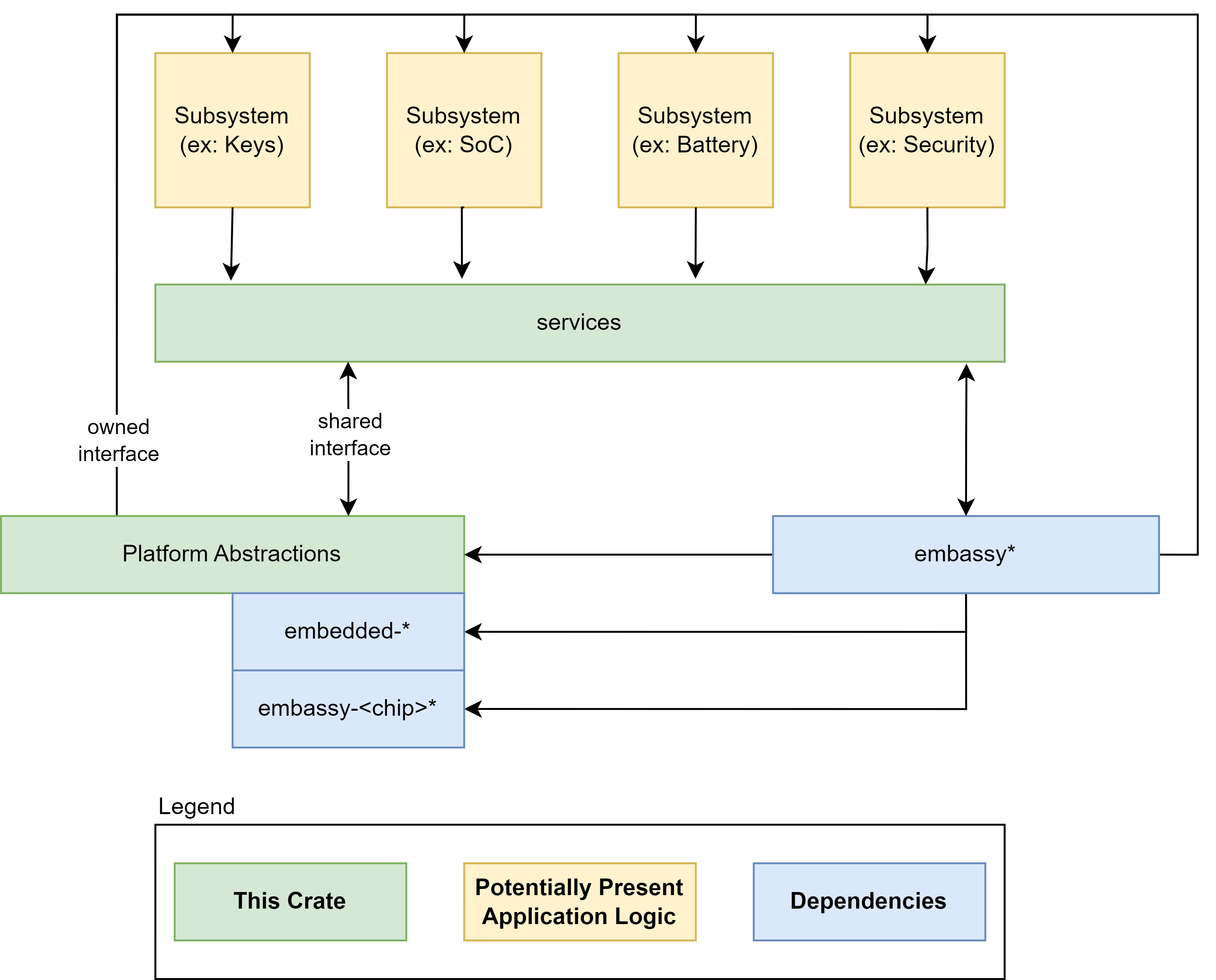
An Embedded Controller is typically a single SOC (System on Chip) design capable of managing a number of low-level tasks.
These individual tasked components of the SOC are represented by the gold boxes in the diagram. The ODP Support for Embedded Controller development is represented in the diagram in the green boxes, whereas third party support libraries are depicted in blue.
Component modularity
A Component can be thought of as a stack of functionality defined by traits (A trait in Rust is analogous to an interface in other common languages).
For the functionality defined by the trait definition to interact with the hardware, there must be a HAL (hardware abstraction layer) defined that implements key actions required by the hardware to conduct these tasks. These HAL actions are then controlled by the functional interface of the component definition.
The component definition is part of a Subsystem of functionality that belongs to a Service.
For example, a Power Policy Service may host several related Subsystems for Battery, Charger, etc. Each of these Subsystems have Controllers to interact with their corresponding components. These Controllers are commanded by the Service their Subsystem belongs to, so for example, the power policy service may interrogate the current charge state of the battery. It does so by interrogating the Subsystem Controller which in turn relies upon the interface defined by the component Trait, which finally calls upon the hardware HAL to retrieve the necessary data from the hardware. This chain of stacked concerns forms a common pattern that allows for agile modularity and flexible portability of components between target contexts.
flowchart TD
    A[e.g. Power Policy Service<br><i>Service initiates query</i>]
    B[Subsystem Controller<br><i>Orchestrates component behavior</i>]
    C[Component Trait Interface<br><i>Defines the functional contract</i>]
    D[HAL Implementation<br><i>Implements trait using hardware-specific logic</i>]
    E[EC / Hardware Access<br><i>Performs actual I/O operations</i>]

    A --> B
    B --> C
    C --> D
    D --> E

    subgraph Service Layer
        A
    end

    subgraph Subsystem Layer
        B
    end

    subgraph Component Layer
        C
        D
    end

    subgraph Hardware Layer
        E
    end
Secure vs Non-Secure
Communication between Subsystems may be considered to be either a “Secure” channel for data communication or a “Non-Secure” channel. An implementation may use more than one transport for different controller and controller service needs.
Data communication with the embedded controller can be considered an owned interface because it is implemented within the EC architecture itself. It may also tie into an external communication bus such as SPI or I2C for data exhanges between other MCUs or the host, but for purposes of communicating between its own subsystems, it is an internally implemented construct.
A “Secure” transport is one that can validate and trust the data from the channel, using cryptographic signatures and hypervisor isolation to insure the integrity of the data exchanged between subsystems. Not all such channels must necessarily be secure, and indeed in some cases depending upon the components used it may not even be possible to secure a channel. The ODP approach is agnostic to these decisions, and can support either or both patterns of implementation.
Depending upon the hardware architecture and available supporting features, a secure channel may incorporate strong isolation between individual component subsystems through memory access and paging mechanisms and/or hypervisor control.
Two similar sounding, but different models become known here. One is SMM, or “System Management Mode”. SMM is a high-privilege CPU mode for x86 microcontrollers that EC services can utilize to gain access. To facilitate this, the SMM itself must be secured. This is done as part of the boot time validation and attestation of SMM access policies. With this in place, EC Services may be accessed by employing a SMM interrupt.
For A deeper dive into what SMM is, see How SMM isolation hardens the platform
Another term seen about will be “SMC”, or “Secure Memory Control”, which is a technology often found in ARM-based architectures. In this scheme, memory is divided into secure and non-secure areas that are mutally exclusive of each other, as well as a narrow section known as “Non-Secure Callable” which is able to call into the “Secure” area from the “Non-Secure” side.
Secure Memory Control concepts are discussed in detail with this document: TrustZone Technology for Armv8-M Architecture
SMM or SMC adoption has design ramifications for EC Services exchanges, but also affects the decisions made around boot firmware, and we’ll see these terms again when we look at ODP Patina implementations.
Hypervisor context multiplexing
Another component of a Secure EC design is the use of a hypervisor to constrain the scope of any given component service to a walled-off virtualization context. One such discussion of such use is detailed in this article
The Open Device Partnership defines:
- An “owned interface” that communicates with the underlying hardware via the available data transport .
- We can think of this transport as being a channel that is considered either “Secure” or “Non-Secure”.
- This interface supports business logic for operational abstractions and concrete implementations to manipulate or interrogate the connected hardware component.
- The business logic code may rely upon other crates to perform its functions. There are several excellent crates available in the Rust community that may be leveraged, such as Embassy.
- Synchronous and asynchronous patterns are supported.
- No runtime or RTOS dependencies.
An implementation may look a little like this:

EC Services
Embedded controller services are available for the operating system to call for various higher-level purposes dictated by specification. The Windows Operating system defines some of these standard services for its platform.
These service interfaces include those for:
- debug services
- firmware management services
- input management services
- oem services
- power services
- time services
Services may be available for operating systems other than Windows.
OEMs may wish to implement their own services as part of their product differentiation.
EC Service communication protocols
With a communication channel protocol established between OS and EC, operating system agents and applications are able to monitor and operate peripheral controllers from application space.
This scope comes with some obvious security ramifications that must be recognized.
Implementations of ODP may be architected for both Secure and Non-Secure system firmware designs, as previously discussed.
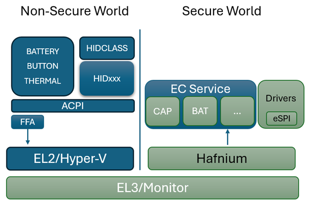
In the diagram above, the dark blue sections are those elements that are part of normal (non-secure) memory space and may be called from a service interface directly. As we can see on the Non-Secure side, the ACPI transport channel has access to the EC component implementations either directly or through the FF-A (Firmware Framework Memory Management Protocol).
FF-A
The Firmware Framework Memory Management Protocol (Spec) describes the relationship of a hypervisor controlling a set of secure memory partitions with configurable access and ownership attributes and the protocol for exchanging information between these virtualized contexts.
FF-A is available for Arm devices only. A common solution for x64 is still in development. For x64 implementations, use of SMM is employed to orchestrate hypervisor access using the [Hafnium] Rust product.
In a Non-Secure implementation without a hypervisor, the ACPI connected components can potentially change the state within any accessible memory space. An implementation with a hypervisor cannot. It may still be considered a “Non-Secure” implementation, however, as the ACPI data itself is unable to be verified for trust.
In a fully “Secure” implementation, controller code is validated at boot time to insure the trust of the data it provides. Additionally, for certain types of data, digital signing and/or encryption may be used on the data exchanged to provide an additional level of trust.
Sample System Implementation
This is short sample implementing a thermal control service interface. This sample assumes one thermal sensor and one thermal control device accessible via ACPI. For an ARM implementation, FF-A and Hafnium is assumed. For x86/x64, an eSPI transport is assumed and direct (Non-Secure) access is made from there.
FFA Device Definition
#![allow(unused)]
fn main() {
Device(\\_SB_.FFA0) {
  Name(_HID, "MSFT000C")
  OperationRegion(AFFH, FFixedHw, 4, 144)
  Field(AFFH, BufferAcc, NoLock, Preserve) { AccessAs(BufferAcc, 0x1), FFAC, 1152 }

  // Other components check this to make sure FFA is available
  Method(AVAL, 0, Serialized) {
    Return(One)
  }

  // Register notification events from FFA
  Method(_RNY, 0, Serialized) {
    Return( Package() {
      Package(0x2) { // Events for Management Service
        ToUUID("330c1273-fde5-4757-9819-5b6539037502"),
        Buffer() {0x1,0x0} // Register event 0x1
      },
      Package(0x2) { // Events for Thermal service
        ToUUID("31f56da7-593c-4d72-a4b3-8fc7171ac073"),
        Buffer() {0x1,0x0,0x2,0x0,0x3,0x0} // Register events 0x1, 0x2, 0x3
      },
      Package(0x2) { // Events for input device
        ToUUID("e3168a99-4a57-4a2b-8c5e-11bcfec73406"),
        Buffer() {0x1,0x0} // Register event 0x1 for LID
      }
    } )
  }

  Method(_NFY, 2, Serialized) {
    // Arg0 == UUID
    // Arg1 == Notify ID
    // Management Service Events

    If(LEqual(ToUUID("330c1273-fde5-4757-9819-5b6539037502"),Arg0)) {
      Switch(Arg1) {
        Case(1) { // Test Notification Event
          Notify(\\_SB.ECT0,0x20)
        }
      }
    }

    // Thermal service events
    If(LEqual(ToUUID("31f56da7-593c-4d72-a4b3-8fc7171ac073"),Arg0)) {
      Switch(Arg1) {
        Case(1) { // Temp crossed low threshold
          Notify(\\_SB.SKIN,0x80)
        }
        Case(2) { // Temp crossed high threshold
          Notify(\\_SB.SKIN,0x81)
        }
        Case(3) { // Critical temperature event
          Notify(\\_SB.SKIN,0x82)
        }
      }
    }

    // Input Device Events
    If(LEqual(ToUUID("e3168a99-4a57-4a2b-8c5e-11bcfec73406"),Arg0)) {
      Switch(Arg1) {
        Case(1) { // LID event
          Notify(\\_SB._LID,0x80)
        }
      }
    }
  }
}
}
Memory Mapped Interface via FFA for UCSI
Note for this implementation of memory mapped interface to work the memory must be marked as reserved by UEFI and not used by the OS and direct access also given to the corresponding service in secure world.
#![allow(unused)]
fn main() {
Device(USBC) {
  Name(_HID,EISAID(“USBC000”))
  Name(_CID,EISAID(“PNP0CA0”))
  Name(_UID,1)
  Name(_DDN, “USB Type-C”)
  Name(_ADR,0x0)
  OperationRegion(USBC, SystemMemory, UCSI_PHYS_MEM, 0x30)
  Field(USBC,AnyAcc,Lock,Preserve)
  {
    // USB C Mailbox Interface
    VERS,16, // PPM-\>OPM Version
    RES, 16, // Reservied
    CCI, 32, // PPM-\>OPM CCI Indicator
    CTRL,64, // OPM-\>PPM Control Messages
    MSGI,128, // OPM-\>PPM Message In
    MSGO,128, // PPM-\>OPM Message Out
  }

  Method(_DSM,4,Serialized,0,UnknownObj, {BuffObj, IntObj,IntObj,PkgObj})
  {

    // Compare passed in UUID to Supported UUID
    If(LEqual(Arg0,ToUUID(“6f8398c2-7ca4-11e4-ad36-631042b5008f”)))
    {
      // Use FFA to send Notification event down to copy data to EC
      If(LEqual(\\_SB.FFA0.AVAL,One)) {
        Name(BUFF, Buffer(144){}) // Create buffer for send/recv data
        CreateByteField(BUFF,0,STAT) // Out – Status for req/rsp
        CreateByteField(BUFF,1,LENG) // In/Out – Bytes in req, updates bytes returned
        CreateField(BUFF,16,128,UUID) // UUID of service
        CreateByteField(BUFF,18, CMDD) // In – First byte of command
        CreateField(BUFF,144,1024,FIFD) // Out – Msg data

        // Create Doorbell Event
        Store(20, LENG)
        Store(0x0, CMDD) // UCSI set doorbell
        Store(ToUUID("daffd814-6eba-4d8c-8a91-bc9bbf4aa301"), UUID)
        Store(Store(BUFF, \_SB_.FFA0.FFAC), BUFF)
      } // End AVAL
    } // End UUID
  } // End DSM
}
}
Thermal ACPI Interface for FFA
This sample code shows one Microsoft Thermal zone for SKIN and then a thermal device THRM for implementing customized IO.
#![allow(unused)]
fn main() {
// Sample Definition of FAN ACPI
Device(SKIN) {
  Name(_HID, "MSFT000A")

  Method(_TMP, 0x0, Serialized) {
    If(LEqual(\\_SB.FFA0.AVAL,One)) {
      Name(BUFF, Buffer(30){})
      CreateByteField(BUFF,0,STAT) // Out – Status for req/rsp
      CreateByteField(BUFF,1,LENG) // In/Out – Bytes in req, updates bytes returned
      CreateField(BUFF,16,128,UUID) // UUID of service
      CreateByteField(BUFF,18,CMDD) // Command register
      CreateByteField(BUFF,19,TZID) // Temp Sensor ID
      CreateDWordField(BUFF,26,RTMP) // Output Data

      Store(20, LENG)
      Store(0x1, CMDD) // EC_THM_GET_TMP
      Store(0x2, TZID) // Temp zone ID for SKIIN
      Store(ToUUID("31f56da7-593c-4d72-a4b3-8fc7171ac073"), UUID)
      Store(Store(BUFF, \\_SB_.FFA0.FFAC), BUFF)

      If(LEqual(STAT,0x0) ) // Check FF-A successful?
      {
        Return (RTMP)
      }
    }
    Return (Ones)
  }

  // Arg0 Temp sensor ID
  // Arg1 Package with Low and High set points
  Method(THRS,0x2, Serialized) {
    If(LEqual(\\_SB.FFA0.AVAL,One)) {
      Name(BUFF, Buffer(32){})
      CreateByteField(BUFF,0,STAT) // Out – Status for req/rsp
      CreateByteField(BUFF,1,LENG) // In/Out – Bytes in req, updates bytes returned
      CreateField(BUFF,16,128,UUID) // UUID of service
      CreateByteField(BUFF,18,CMDD) // Command register
      CreateByteField(BUFF,19,TZID) // Temp Sensor ID
      CreateDwordField(BUFF,20,VTIM) // Timeout
      CreateDwordField(BUFF,24,VLO) // Low Threshold
      CreateDwordField(BUFF,28,VHI) // High Threshold
      CreateDWordField(BUFF,18,TSTS) // Output Data

      Store(ToUUID("31f56da7-593c-4d72-a4b3-8fc7171ac073"), UUID)
      Store(32, LENG)
      Store(0x2, CMDD) // EC_THM_SET_THRS
      Store(Arg0, TZID)
      Store(DeRefOf(Index(Arg1,0)),VTIM)
      Store(DeRefOf(Index(Arg1,1)),VLO)
      Store(DeRefOf(Index(Arg1,2)),VHI)
      Store(Store(BUFF, \\_SB_.FFA0.FFAC), BUFF)

      If(LEqual(STAT,0x0) ) // Check FF-A successful?
      {
        Return (TSTS)
      }
    }
    Return (0x3) // Hardware failure
  }

  // Arg0 GUID 1f0849fc-a845-4fcf-865c-4101bf8e8d79
  // Arg1 Revision
  // Arg2 Function Index
  // Arg3 Function dependent
  Method(_DSM, 0x4, Serialized) {
    If(LEqual(ToUuid("1f0849fc-a845-4fcf-865c-4101bf8e8d79"),Arg0)) {
      Switch(Arg2) {
        Case (0) {
          Return(0x3) // Support Function 0 and Function 1
        }
        Case (1) {
          Return( THRS(0x2, Arg3) ) // Call to function to set threshold
        }
      }
    }
    Return(0x3)
  }
}

Device(THRM) {
  Name(_HID, "MSFT000B")

  // Arg0 Instance ID
  // Arg1 UUID of variable
  // Return (Status,Value)
  Method(GVAR,2,Serialized) {
    If(LEqual(\\_SB.FFA0.AVAL,One)) {
      Name(BUFF, Buffer(38){})
      CreateByteField(BUFF,0,STAT) // Out – Status for req/rsp
      CreateByteField(BUFF,1,LENG) // In/Out – Bytes in req, updates bytes returned
      CreateField(BUFF,16,128,UUID) // UUID of service
      CreateByteField(BUFF,18,CMDD) // Command register
      CreateByteField(BUFF,19,INST) // Instance ID
      CreateWordField(BUFF,20,VLEN) // 16-bit variable length
      CreateField(BUFF,176,128,VUID) // UUID of variable to read
      CreateField(BUFF,208,64,RVAL) // Output Data

      Store(ToUUID("31f56da7-593c-4d72-a4b3-8fc7171ac073"), UUID)
      Store(38, LENG)
      Store(0x5, CMDD) // EC_THM_GET_VAR
      Store(Arg0,INST) // Save instance ID
      Store(4,VLEN) // Variable is always DWORD here
      Store(Arg1, VUID)
      Store(Store(BUFF, \\_SB_.FFA0.FFAC), BUFF)

      If(LEqual(STAT,0x0) ) // Check FF-A successful?
      {
        Return (RVAL)
      }
    }
    Return (0x3)
  }

  // Arg0 Instance ID
  // Arg1 UUID of variable
  // Return (Status,Value)
  Method(SVAR,3,Serialized) {
    If(LEqual(\\_SB.FFA0.AVAL,One)) {
      Name(BUFF, Buffer(42){})
      CreateByteField(BUFF,0,STAT) // Out – Status for req/rsp
      CreateByteField(BUFF,1,LENG) // In/Out – Bytes in req, updates bytes returned
      CreateField(BUFF,16,128,UUID) // UUID of service
      CreateByteField(BUFF,18,CMDD) // Command register
      CreateByteField(BUFF,19,INST) // Instance ID
      CreateWordField(BUFF,20,VLEN) // 16-bit variable length
      CreateField(BUFF,176,128,VUID) // UUID of variable to read
      CreateDwordField(BUFF,38,DVAL) // Data value
      CreateField(BUFF,208,32,RVAL) // Ouput Data

      Store(ToUUID("31f56da7-593c-4d72-a4b3-8fc7171ac073"), UUID)
      Store(42, LENG)
      Store(0x6, CMDD) // EC_THM_SET_VAR
      Store(Arg0,INST) // Save instance ID
      Store(4,VLEN) // Variable is always DWORD here
      Store(Arg1, VUID)
      Store(Arg2,DVAL)
      Store(Store(BUFF, \\_SB_.FFA0.FFAC), BUFF)

      If(LEqual(STAT,0x0) ) // Check FF-A successful?
      {
      Return (RVAL)
      }
    }
    Return (0x3)
  }

  // Arg0 GUID
  // 07ff6382-e29a-47c9-ac87-e79dad71dd82 - Input
  // d9b9b7f3-2a3e-4064-8841-cb13d317669e - Output
  // Arg1 Revision
  // Arg2 Function Index
  // Arg3 Function dependent
  Method(_DSM, 0x4, Serialized) {
    // Input Variable
    If(LEqual(ToUuid("07ff6382-e29a-47c9-ac87-e79dad71dd82"),Arg0)) {
      Switch(Arg2) {
        Case(0) {
          // We support function 0-3
          Return(0xf)
        }
        Case(1) {
          Return(GVAR(1,ToUuid("ba17b567-c368-48d5-bc6f-a312a41583c1"))) // OnTemp
        }
        Case(2) {
          Return(GVAR(1,ToUuid("3a62688c-d95b-4d2d-bacc-90d7a5816bcd"))) // RampTemp
        }
        Case(3) {
          Return(GVAR(1,ToUuid("dcb758b1-f0fd-4ec7-b2c0-ef1e2a547b76"))) // MaxTemp
        }
      }
      Return(0x1)
    }

    // Output Variable
    If(LEqual(ToUuid("d9b9b7f3-2a3e-4064-8841-cb13d317669e"),Arg0)) {
      Switch(Arg2) {
        Case(0) {
          // We support function 0-3
          Return(0xf)
        }
        Case(1) {
          Return(SVAR(1,ToUuid("ba17b567-c368-48d5-bc6f-a312a41583c1"),Arg3)) // OnTemp
        }
        Case(2) {
          Return(SVAR(1,ToUuid("3a62688c-d95b-4d2d-bacc-90d7a5816bcd"),Arg3)) // RampTemp
        }
        Case(3) {
          Return(SVAR(1,ToUuid("dcb758b1-f0fd-4ec7-b2c0-ef1e2a547b76"),Arg3)) // MaxTemp
        }
      }
    }
    Return (0x1)
  }
}
}
Call Flows for secure and non-secure Implementation
Depending on system requirements the ACPI calls may go directly to the EC or through secure world then through to EC.
When using non-secure interface the ACPI functions must define protocol level which is the Embedded controller for eSPI. For I2C/I3C or SPI interfaces the corresponding ACPI device must define the bus dependency and build the packet directly that is sent to the EC.
For secure communication all data is sent to the secure world via FF-A commands described in this document and the actual bus protocol and data sent to the EC is defined in the secure world in Hafnium. All support for FF-A is inboxed in the OS by default so EC communication will always work in any environment. However, FF-A is not supported in x86/x64 platforms so direct EC communication must be used on these platforms.
Non-Secure eSPI Access
This call flow assumes using Embedded controller definition with independent ACPI functions for MPTF support
Non-Secure eSPI READ
#![allow(unused)]
fn main() {
Device(EC0) {
  Name(_HID, EISAID("PNP0C09")) // ID for this EC

  // current resource description for this EC
  Name(_CRS, ResourceTemplate() {
    Memory32Fixed (ReadWrite, 0x100000, 0x10) // Used for simulated port access
    Memory32Fixed (ReadWrite, 0x100010, 0x10)
    // Interrupt defined for eSPI event signalling
    GpioInt(Edge, ActiveHigh, ExclusiveAndWake,PullUp 0,"\\_SB.GPI2"){43}
  })

  Name(_GPE, 0) // GPE index for this EC

  // create EC's region and field for thermal support
  OperationRegion(EC0, EmbeddedControl, 0, 0xFF)
  Field(EC0, ByteAcc, Lock, Preserve) {
    MODE, 1, // thermal policy (quiet/perform)
    FAN, 1, // fan power (on/off)
    , 6, // reserved
    TMP, 16, // current temp
    AC0, 16, // active cooling temp (fan high)
    , 16, // reserved
    PSV, 16, // passive cooling temp
    HOT 16, // critical S4 temp
    CRT, 16 // critical temp
    BST1, 32, // Battery State
    BST2, 32, // Battery Present Rate
    BST3, 32, // Battery Remaining capacity
    BST4, 32, // Battery Present Voltage
  }

  Method (_BST) {
    Name (BSTD, Package (0x4)
    {
      \\_SB.PCI0.ISA0.EC0.BST1, // Battery State
      \\_SB.PCI0.ISA0.EC0.BST2, // Battery Present Rate
      \\_SB.PCI0.ISA0.EC0.BST3, // Battery Remaining Capacity
      \\_SB.PCI0.ISA0.EC0.BST4, // Battery Present Voltage
    })
    Return(BSTD)
  }
}
}
sequenceDiagram OSPM->>ACPI: call _BST method ACPI->>ACPI: Map to EC0 fields in EC operation Region ACPI->>ACPI: EC0 accesses change to eSPI Peripheral accesses ACPI->>eSPI: Each field acccess changed to peripheral read/write ACPI->>ACPI: ACI handles SCI, port IO, MMIO, serialized ACPI->>ACPI: eSPI read/writes complete ACPI->>ACPI: Data is reorganized to _BST structure ACPI->>OSPM: Return _BST structure with status
Non-Secure eSPI Notifications
All interrupts are handled by the ACPI driver. When EC needs to send a notification event the GPIO is asserted and traps into IRQ. ACPI driver reads the EC_SC status register to determine if an SCI is pending. DPC callback calls and reads the EC_DATA port to determine the _Qxx event that is pending. Based on the event that is determined by ACPI the corresponding _Qxx event function is called.
#![allow(unused)]
fn main() {
Method (_Q07) {
  // Take action for event 7
  Notify(\\_SB._LID, 0x80)
}
}
sequenceDiagram EC->>SCI ISR: EC asserts alert (IRQ) SCI ISR->>SCI DPC: Schedule DPC if EC_SC indicates SCI SCI DPC->>EC: Read EC_DATA to determine event EC->>SCI DPC: Send Qxx event SCI DPC->>ACPI: Call _Qxx function in EC0
Secure eSPI Access
The following flow assumes ARM platform using FF-A for secure calls. Note if you want to use the same EC firmware on both platforms with secure and non-secure access the EC_BAT_GET_BST in this case should be convert to a peripheral access with the same IO port and offset as non-secure definition.
Secure eSPI READ
#![allow(unused)]
fn main() {
Method (_BST) {
  // Check to make sure FFA is available and not unloaded
  If(LEqual(\\_SB.FFA0.AVAL,One)) {
    Name(BUFF, Buffer(32){}) // Create buffer for send/recv data
    CreateByteField(BUFF,0,STAT) // Out – Status for req/rsp
    CreateByteField(BUFF,1,LENG) // In/Out – Bytes in req, updates bytes returned
    CreateField(BUFF,16,128,UUID) // UUID of service
    CreateByteField(BUFF,18, CMDD) // In – First byte of command
    CreateDwordField(BUFF,19, BMA1) // In – Averaging Interval
    CreateField(BUFF,144,128,BSTD) // Out – 4 DWord BST data

    Store(ToUUID("25cb5207-ac36-427d-aaef-3aa78877d27e"), UUID) // Battery
    Store(42, LENG)
    Store(0x6, CMDD) // EC_BAT_GET_BST
    Store(Store(BUFF, \\_SB_.FFA0.FFAC), BUFF)

    If(LEqual(STAT,0x0) ) // Check FF-A successful?
    {
    Return (BMAD)
    }
  }
  Return(Zero)
}
}
sequenceDiagram OSPM->>ACPI: call_BST method ACPI->>FFA: Send EC_BAT_GET_BST_request FFA->>EC Service: Forward EC_BAT_GET_BST_request EC Service->>EC Service: Convert to eSPI peripheral read/write EC Service->>eSPI: send peripheral read/write access EC Service->>FFA: FFA_YIELD (as needed) FFA->>EC Service: FFA_RESUME (check for complete) eSPI->>EC Service: Return peripheral read data EC Service->>EC Service: Convert to EC_BAT_GET_BST response EC Service->>FFA: FFA response to original request FFA->>ACPI: return FFA status and _BST response ACPI->OSPM: return _BST structure
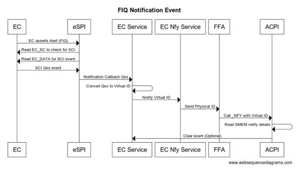
Secure eSPI Notification
When EC communication is done through Secure world we assert FIQ which is handled as eSPI interrupt. eSPI driver reads EC_SC and EC_DATA to retrieve the notification event details. On Non-secure implementation ACPI converts this to Qxx callback. On secure platform this is converted to a virtual ID and sent back to the OS via _NFY callback and a virtual ID.
#![allow(unused)]
fn main() {
Method(_NFY, 2, Serialized) {
  // Arg0 == UUID
  // Arg1 == Notify ID
  If(LEqual(ToUUID("25cb5207-ac36-427d-aaef-3aa78877d27e"),Arg0)) {
    If(LEqual(0x2,Arg1)) {
      Store(Arg1, \\_SB.ECT0.NEVT)
      Notify(\\_SB._LID, 0x80)
    }
  }
}
}
sequenceDiagram EC->>eSPI: EC asserts Alert (FIQ) eSPI->>EC: Read EC_SC to check for SCI eSPI->>EC: Read EC_DATA for SCI event EC->>eSPI: SCI Qxx event eSPI->>EC Service: Notification callback Qxx EC Service->>EC Service: Convert qxx to Virtual ID EC Service->>EC Nfy Service: Notify Virtual ID EC Nfy Service->>FFA:Send Physical ID FFA->>ACPI:Call_NFY with Virtual ID ACPI->>ACPI: Read SMEM notify details ACPI--)EC Service: Clear event (optional)
Legacy EC Interface
ACPI specification has a definition for an embedded controller, however this implementation is tied very closely to the eSPI bus and x86 architecture.
The following is an example of legacy EC interface definition from ACPI
11.7. Thermal Zone Examples — ACPI Specification 6.4 documentation
#![allow(unused)]
fn main() {
Scope(\\_SB.PCI0.ISA0) {
  Device(EC0) {
    Name(_HID, EISAID("PNP0C09")) // ID for this EC

    // current resource description for this EC
    Name(_CRS, ResourceTemplate() {
      IO(Decode16,0x62,0x62,0,1)
      IO(Decode16,0x66,0x66,0,1)
    })

    Name(_GPE, 0) // GPE index for this EC

    // create EC's region and field for thermal support
    OperationRegion(EC0, EmbeddedControl, 0, 0xFF)
    Field(EC0, ByteAcc, Lock, Preserve) {
      MODE, 1, // thermal policy (quiet/perform)
      FAN, 1, // fan power (on/off)
      , 6, // reserved
      TMP, 16, // current temp
      AC0, 16, // active cooling temp (fan high)
      , 16, // reserved
      PSV, 16, // passive cooling temp
      HOT 16, // critical S4 temp
      CRT, 16 // critical temp
    }

    // following is a method that OSPM will schedule after
    // it receives an SCI and queries the EC to receive value 7
    Method(_Q07) {
      Notify (\\_SB.PCI0.ISA0.EC0.TZ0, 0x80)
    } // end of Notify method

    // fan cooling on/off - engaged at AC0 temp
    PowerResource(PFAN, 0, 0) {
      Method(_STA) { Return (\\_SB.PCI0.ISA0.EC0.FAN) } // check power state
      Method(_ON) { Store (One, \\\\_SB.PCI0.ISA0.EC0.FAN) } // turn on fan
      Method(_OFF) { Store ( Zero, \\\\_SB.PCI0.ISA0.EC0.FAN) }// turn off
fan
    }

    // Create FAN device object
    Device (FAN) {
    // Device ID for the FAN
    Name(_HID, EISAID("PNP0C0B"))
    // list power resource for the fan
    Name(_PR0, Package(){PFAN})
    }

    // create a thermal zone
    ThermalZone (TZ0) {
      Method(_TMP) { Return (\\_SB.PCI0.ISA0.EC0.TMP )} // get current temp
      Method(_AC0) { Return (\\_SB.PCI0.ISA0.EC0.AC0) } // fan high temp
      Name(_AL0, Package(){\\_SB.PCI0.ISA0.EC0.FAN}) // fan is act cool dev
      Method(_PSV) { Return (\\_SB.PCI0.ISA0.EC0.PSV) } // passive cooling
temp
      Name(_PSL, Package (){\\_SB.CPU0}) // passive cooling devices
      Method(_HOT) { Return (\\_SB.PCI0.ISA0.EC0.HOT) } // get critical S4
temp
      Method(_CRT) { Return (\\_SB.PCI0.ISA0.EC0.CRT) } // get critical temp
      Method(_SCP, 1) { Store (Arg1, \\\\_SB.PCI0.ISA0.EC0.MODE) } // set
cooling mode

      Name(_TSP, 150) // passive sampling = 15 sec
      Name(_TZP, 0) // polling not required
      Name (_STR, Unicode ("System thermal zone"))
    } // end of TZ0
  } // end of ECO
} // end of \\\\_SB.PCI0.ISA0 scope-
}
On platforms that do not support IO port access there is an option to define MMIO regions to simulate the IO port transactions.
In the above example you can see that the operation region directly maps to features on the EC and you can change the EC behavior by writing to a byte in the region or reading the latest data from the EC.
For a system with the EC connected via eSPI and that needs a simple non-secure interface to the EC the above mapping works very well and keeps the code simple. The eSPI protocol itself has details on port accesses and uses the peripheral channel to easily read/write memory mapped regions.
As the EC features evolve there are several requirements that do no work well with this interface:
-
Different buses such as I3C, SPI, UART target a packet request/response rather than a memory mapped interface
-
Protected or restricted access and validation of request/response
-
Firmware update, large data driven requests that require larger data response the 256-byte region is limited
-
Discoverability of features available and OEM customizations
-
Out of order completion of requests, concurrency, routing and priority handling
As we try to address these limitations and move to a more packet based protocol described in this document. The following section covers details on how to adopt existing operation region to new ACPI functionality.
Adopting EC Operation Region
The new OS frameworks such as MPTF still use ACPI methods as primary interface. Instead of defining devices such as FAN or ThermalZone in the EC region you can simply define the EC region itself and then map all the other ACPI functions to operate on this region. This will allow you to maintain backwards compatibility with existing EC definitions.
#![allow(unused)]
fn main() {
Device(EC0) {
  Name(_HID, EISAID("PNP0C09")) // ID for this EC
  // current resource description for this EC
  Name(_CRS, ResourceTemplate() {
    IO(Decode16,0x62,0x62,0,1)
    IO(Decode16,0x66,0x66,0,1)
  })

  // create EC's region and field for thermal support
  OperationRegion(EC0, EmbeddedControl, 0, 0xFF)
  Field(EC0, ByteAcc, Lock, Preserve) {
    MODE, 1, // thermal policy (quiet/perform)
    FAN, 1, // fan power (on/off)
    , 6, // reserved
    TMP, 16, // current temp
    AC0, 16, // active cooling temp (fan high)
    , 16, // reserved
    PSV, 16, // passive cooling temp
    HOT 16, // critical S4 temp
    CRT, 16 // critical temp
  }
}

Device(SKIN) {
  Name(_HID, "MSFT000A") // New MPTF HID Temperature Device
  Method(_TMP, 0x0, Serialized) {
      Return( \\_SB.PCI0.ISA0.EC0.TMP)
  }
}
}
For more complicated functions that take a package some of the data may be constructed within ACPI and some of the data pulled from the OperationRegion. For example BIX for battery information may have a combination of static and dynamic data like this:
#![allow(unused)]
fn main() {
Method (_BIX) {
  Name (BAT0, Package (0x12)
  {
    0x01, // Revision
    0x02, // Power Unit
    0x03, // Design Capacity
    \\_SB.PCI0.ISA0.EC0.BFCC, // Last Full Charge Capacity
    0x05, // Battery Technology
    0x06, // Design Voltage
    0x07, // Design capacity of Warning
    0x08, // Design Capacity of Low
    \\_SB.PCI0.ISA0.EC0.BCYL, // Cycle Count
    0x0A, // Measurement Accuracy
    0x0B, // Max Sampling Time
    0x0C, // Min Sampling Time
    0x0D, // Max Averaging Interval
    0x0E, // Min Averaging Interval
    0x0F, // Battery Capacity Granularity 1
    0x10, // Battery Capacity Granularity 2
    "Model123", // Model Number
    "Serial456", // Serial Number
    "Li-Ion", // Battery Type
    "OEMName" // OEM Information
  })
  Return(BAT0)
}
}
Limitations for using Legacy EC
Before using the Legacy EC definition OEM’s should be aware of several use cases that may limit you ability to use it.
ACPI support for eSPI master
In the case of Legacy EC the communication to the EC is accomplished directly by the ACPI driver using PORT IO and eSPI Peripheral Bus commands. On ARM platforms there is no PORT IO and these must be substituted with MMIO regions. The ACPI driver needs changes to support MMIO which is being evaluated and support is not yet available. Some Silicon Vendors also do not implement the full eSPI specification and as such the ACPI driver cannot handle all the communication needs. On these platforms using Legacy EC interface is not an option.
Security of eSPI bus
When non-secure world is given access to the eSPI bus it can send commands to device on that bus. Some HW designs have the TPM or SPINOR on the same physical bus as the EC. On these designs allowing non-secure world to directly sends commands to EC can break the security requirements of other devices on the bus. In these cases the eSPI communication must be done in the secure world over FF-A as covered in this document and not use the Legacy EC channel. Since non-secure world has complete access to the EC operation region there is no chance for encryption of data. All data in the operation region is considered non-secure.
Functional limitations of Legacy EC
The peripheral region that is mapped in the Legacy EC in ACPI is limited to 256 bytes and notification events to the ones that are defined and handled in ACPI driver. To create custom solutions, send large packets or support encryption of data the Legacy EC interface has limitations in this area.
Secure EC Services Overview
In this section we review a system design where the EC communication is in the secure world running in a dedicated SP. In a system without secure world or where communication to EC is not desired to be secure all the ACPI functions can be mapped directly to data from the EC operation region.
The following github projects provide sample implementations of this interface:
ACPI EC samples, Kernel mode test driver, User mode test driver
Sample Secure Partition Service for EC services in RUST
RUST crate for FFA implementation in secure partition
The following GUID’s have been designed to represent each service operating in the secure partition for EC.
| EC Service Name | Service GUID | Description | EC_SVC_MANAGEMENT | 330c1273-fde5-4757-9819-5b6539037502 | Used to query EC functionality, Board info, version, security state, FW update | EC_SVC_POWER | 7157addf-2fbe-4c63-ae95-efac16e3b01c | Handles general power related requests and OS Sx state transition state notification | EC_SVC_BATTERY | 25cb5207-ac36-427d-aaef-3aa78877d27e | Handles battery info, status, charging | EC_SVC_THERMAL | 31f56da7-593c-4d72-a4b3-8fc7171ac073 | Handles thermal requests for skin and other thermal events | EC_SVC_UCSI | 65467f50-827f-4e4f-8770-dbf4c3f77f45 | Handles PD notifications and calls to UCSI interface | EC_SVC_INPUT | e3168a99-4a57-4a2b-8c5e-11bcfec73406 | Handles wake events, power key, lid, input devices (HID separate instance) | EC_SVC_TIME_ALARM | 23ea63ed-b593-46ea-b027-8924df88e92f | Handles RTC and wake timers. | EC_SVC_DEBUG | 0bd66c7c-a288-48a6-afc8-e2200c03eb62 | Used for telemetry, debug control, recovery modes, logs, etc | EC_SVC_TEST | 6c44c879-d0bc-41d3-bef6-60432182dfe6 | Used to send commands for manufacturing/factory test | EC_SVC_OEM1 | 9a8a1e88-a880-447c-830d-6d764e9172bb | Sample OEM custom service and example piping of events |
|---|
FFA Overview
This section covers the components involved in sending a command to EC through the FFA flow in windows. This path is specific to ARM devices and a common solution with x64 is still being worked out. Those will continue through the non-secure OperationRegion in the near term.

ARM has a standard for calling into the secure world through SMC’s and targeting a particular service running in secure world via a UUID. The full specification and details can be found here: Firmware Framework for A-Profile
The windows kernel provides native ability for ACPI to directly send and receive FFA commands. It also provides a driver ffadrv.sys to expose a DDI that allows other drivers to directly send/receive FFA commands without needing to go through ACPI.
Hyper-V forwards the SMC’s through to EL3 to Hafnium which then uses the UUID to route the request to the correct SP and service. From the corresponding EC service it then calls into the eSPI or underlying transport layer to send and receive the request to the physical EC.
FFA Device Definition
The FFA device is loaded from ACPI during boot and as such requires a Device entry in ACPI
#![allow(unused)]
fn main() {
  Name(_HID, "MSFT000C")

  OperationRegion(AFFH, FFixedHw, 4, 144)
  Field(AFFH, BufferAcc, NoLock, Preserve) { AccessAs(BufferAcc, 0x1), FFAC, 1152 }


  Name(_DSD, Package() {
      ToUUID("daffd814-6eba-4d8c-8a91-bc9bbf4aa301"), //Device Prop UUID
      Package() {
        Package(2) {
          "arm-arml0002-ffa-ntf-bind",
          Package() {
              1, // Revision
              2, // Count of following packages
              Package () {
                     ToUUID("330c1273-fde5-4757-9819-5b6539037502"), // Service1 UUID
                     Package () {
                          0x01,     //Cookie1 (UINT32)
                          0x07,     //Cookie2
                      }
              },
              Package () {
                     ToUUID("b510b3a3-59f6-4054-ba7a-ff2eb1eac765"), // Service2 UUID
                     Package () {
                          0x01,     //Cookie1
                          0x03,     //Cookie2
                      }
             }
         }
      }
    }
  }) // _DSD()

  Method(_DSM, 0x4, NotSerialized)
  {
    // Arg0 - UUID
    // Arg1 - Revision
    // Arg2: Function Index
    //         0 - Query
    //         1 - Notify
    //         2 - binding failure
    //         3 - infra failure
    // Arg3 - Data

    //
    // Device specific method used to query
    // configuration data. See ACPI 5.0 specification
    // for further details.
    //
    If(LEqual(Arg0, Buffer(0x10) {
        //
        // UUID: {7681541E-8827-4239-8D9D-36BE7FE12542}
        //
        0x1e, 0x54, 0x81, 0x76, 0x27, 0x88, 0x39, 0x42, 0x8d, 0x9d, 0x36, 0xbe, 0x7f, 0xe1, 0x25, 0x42
      }))
    {
      // Query Function
      If(LEqual(Arg2, Zero))
      {
        Return(Buffer(One) { 0x03 }) // Bitmask Query + Notify
      }

      // Notify Function
      If(LEqual(Arg2, One))
      {
        // Arg3 - Package {UUID, Cookie}
        Store(Index(Arg3,1), \_SB.ECT0.NEVT )
        Return(Zero)
      }
    } Else {
      Return(Buffer(One) { 0x00 })
    }
  }

  Method(AVAL,0x0, Serialized)
  {
    Return(One)
  }
}
}
HID definition
The _HID “MSFT000C” is reserved for FFA devices. Defining this HID for your device will cause the FFA interface for the OS to be loaded on this device.
Operation Region Definition
The operation region is marked as FFixedHw type 4 which lets the ACPI interpreter know that any read/write to this region requires special handling. The length is 144 bytes because this region operates on registers X0-X17 each of which are 8 bytes 18*8 = 144 bytes. This is mapped to FFAC is 1152 bits (144*8) and this field is where we act upon.
#![allow(unused)]
fn main() {
OperationRegion(AFFH, FFixedHw, 4, 144)
Field(AFFH, BufferAcc, NoLock, Preserve) { AccessAs(BufferAcc, 0x1),FFAC, 1152 }
}
When reading and writing from this operation region the FFA driver does some underlying mapping for X0-X3
X0 = 0xc400008d // FFA_DIRECT_REQ2
X1 = (Receiver Endpoint ID) | (Sender Endpoint ID \<\< 16)
X2/X3 = UUID
The following is the format of the request and response packets that are sent via ACPI
#![allow(unused)]
fn main() {
FFA_REQ_PACKET
{
  uint8 status; // Not used just populated so commands are symmetric
  uint8 length; // Number of bytes in rawdata
  uint128 UUID;
  uint8 reqdata[];
}

FFA_RSP_PACKET
{
  uint8 status; // Status from ACPI if FFA command was sent successfully
  uint8 length;
  uint128 UUID;
  uint64 ffa_status; // Status returned from the service of the FFA command
  uint8 rspdata[];
}

CreateByteField(BUFF,0,STAT) // Out – Status for req/rsp
CreateByteField(BUFF,1,LENG) // In/Out – Bytes in req, updates bytes returned
CreateField(BUFF,16,128,UUID) // In/Out - UUID of service
CreateDwordField(BUFF,18,FFST)// Out - FFA command status
}
Register Notification
During FFA driver initialization it calls into secure world to get a list of all available services for each secure partition. After this we send a NOTIFICATION_REGISTRATION request to each SP that has a service which registers for notification events
#![allow(unused)]
fn main() {
  Name(_DSD, Package() {
      ToUUID("daffd814-6eba-4d8c-8a91-bc9bbf4aa301"), //Device Prop UUID
      Package() {
        Package(2) {
          "arm-arml0002-ffa-ntf-bind",
          Package() {
              1, // Revision
              1, // Count of following packages
              Package () {
                     ToUUID("330c1273-fde5-4757-9819-5b6539037502"), // Service1 UUID
                     Package () {
                          0x01,     //Cookie1 (UINT32)
                          0x07,     //Cookie2
                      }
              },
         }
      }
    }
  }) // _DSD()
}
In the above example we indicate that the OS will handle 2 different notification events for UUID 330c1273-fde5-4757-9819-5b6539037502 which is our EC management UUID. FFA knows which secure partition this maps to based on the list of services for each SP it has retrieved. Rather than having to keep track of all the physical bits in the bitmask that are used the FFA driver keeps track of this and allows each service to create a list of virtual ID’s they need to handle. The FFA driver then maps this to one of the available bits in the hardware bitmask and passes this mapping down to the notification service running in a given SP.
Input
| Parameter | Register | Value | Function | X4 | 0x1 | UUID Lo | X5 | Bytes [0..7] for the service UUID. | UUID Hi | X6 | Bytes [8..16] for the service UUID. | Mappings Count | X7 | The number of notification mappings | Notification Mapping1 | X8 |
Bits [0..16] – Notification ID. --> 0,1,2,3,...
Bits [16..32] – Notification Bitmap bit number (0-383). |
Notification Mapping2 | X9 |
Bits [0..16] – Notification ID. --> 0,1,2,3,...
Bits [16..32] – Notification Bitmap bit number (0-383).
|
... | ... | ... |
|---|
Output
| Parameter | Register | Value |
|---|---|---|
| Result | X4 | 0 on success. Otherwise, Failure |
Note this NOTIFICATION_REGISTER request is sent to the Notification Service UUID in the SP. The UUID of the service that the notifications are for are stored in X5/X6 registers shown above.
The UUID for notification service is {B510B3A3-59F6-4054-BA7A-FF2EB1EAC765} which is stored in X2/X3.
Notification Events
All notification events sent from all secure partitions are passed back through the FFA driver. The notification calls the _DSM method. Function 0 is always a bitmap of all the other functions supported. We must support at least a minium of the Query and Notify. The UUID is stored in Arg0 and the notification cookie is stored in Arg3 when Arg2 is 11.
#![allow(unused)]
fn main() {
  Method(_DSM, 0x4, NotSerialized)
  {
    // Arg0 - UUID
    // Arg1 - Revision
    // Arg2: Function Index
    //         0 - Query
    //         1 - Notify
    //         2 - binding failure
    //         3 - infra failure
    // Arg3 - Data

    //
    // Device specific method used to query
    // configuration data. See ACPI 5.0 specification
    // for further details.
    //
    If(LEqual(Arg0, Buffer(0x10) {
        //
        // UUID: {7681541E-8827-4239-8D9D-36BE7FE12542}
        //
        0x1e, 0x54, 0x81, 0x76, 0x27, 0x88, 0x39, 0x42, 0x8d, 0x9d, 0x36, 0xbe, 0x7f, 0xe1, 0x25, 0x42
      }))
    {
      // Query Function
      If(LEqual(Arg2, Zero))
      {
        Return(Buffer(One) { 0x03 }) // Bitmask Query + Notify
      }

      // Notify Function
      If(LEqual(Arg2, One))
      {
        // Arg3 - Package {UUID, Cookie}
        Store(Index(Arg3,1), \_SB.ECT0.NEVT )
        Return(Zero)
      }
    } Else {
      Return(Buffer(One) { 0x00 })
    }
  }
}
The following is the call flow showing a secure interrupt arriving to the EC service which results in a notification back to ACPI. The notification payload can optionally be written to a shared buffer or ACPI can make another call back into EC service to retrieve the notification details.
The _NFY only contains the ID of the notification and no other payload, so both ACPI and the EC service must be designed either with shared memory buffer or a further notify data packet.

Runtime Requests
During runtime the non-secure side uses FFA_MSG_SEND_DIRECT_REQ2 requests to send requests to a given service within an SP. Any request that is expected to take longer than 500 uSec should yield control back to the OS by calling FFA_YIELD within the service. When FFA_YIELD is called it will return control back to the OS to continue executing but the corresponding ACPI thread will be blocked until the original FFA request completes with DIRECT_RSP2. Note this creates a polling type interface where the OS will resume the SP thread after the timeout specified. The following is sample call sequence.

FFA Example Data Flow
For an example let’s take the battery status request _BST and follow data through.

#![allow(unused)]
fn main() {
FFA_REQ_PACKET req = {
  0x0, // Initialize to no error
  0x1, // Only 1 byte of data is sent after the header
  {0x25,0xcb,0x52,0x07,0xac,0x36,0x42,0x7d,0xaa,0xef,0x3a,0xa7,0x88,0x77,0xd2,0x7e},
  0x2 // EC_BAT_GET_BST
}
}
The equivalent to write this data into a BUFF in ACPI is as follows
#![allow(unused)]
fn main() {
Name(BUFF, Buffer(32){}) // Create buffer for send/recv data
CreateByteField(BUFF,0,STAT) // Out – Status for req/rsp
CreateByteField(BUFF,1,LENG) // In/Out – Bytes in req, updates bytes returned
CreateField(BUFF,16,128,UUID) // UUID of service
CreateByteField(BUFF,18, CMDD) // In – First byte of command
CreateField(BUFF,144,128,BSTD) // Out – Raw data response 4 DWords
Store(20,LENG)
Store(0x2, CMDD)
Store(ToUUID ("25cb5207-ac36-427d-aaef-3aa78877d27e"), UUID)
Store(Store(BUFF, \\_SB_.FFA0.FFAC), BUFF)
}
The ACPI interpreter when walking through this code creates a buffer and populates the data into buffer. The last line indicates to send this buffer over FFA interface.
ACPI calls into the FFA interface to send the data over to the secure world EC Service
typedef struct _FFA_INTERFACE {
    ULONG Version;
    PFFA_MSG_SEND_DIRECT_REQ2 SendDirectReq2;
} FFA_INTERFACE, \*PFFA_INTERFACE;
FFA Parsing
FFA is in charge of sending the SMC over to the secure world and routing to the correct service based on UUID.

X0 = SEND_DIRECT_REQ2 SMC command ID
X1 = Source ID and Destination ID
X2 = UUID Low
X3 = UUID High
X4-X17 = rawdata
Note: The status and length are not passed through to the secure world they are consumed only be ACPI.
HyperV and Monitor have a chance to filter or deny the request, but in general just pass the SMC request through to Hafnium
Hafnium extracts the data from the registers into an sp_msg structure which is directly mapping contents from x0-x17 into these fields.
#![allow(unused)]
fn main() {
pub struct FfaParams {
    pub x0: u64,
    pub x1: u64,
    pub x2: u64,
    pub x3: u64,
    pub x4: u64,
    pub x5: u64,
    pub x6: u64,
    pub x7: u64,
    pub x8: u64,
    pub x9: u64,
    pub x10: u64,
    pub x11: u64,
    pub x12: u64,
    pub x13: u64,
    pub x14: u64,
    pub x15: u64,
    pub x16: u64,
    pub x17: u64,
}
}
In our SP we receive the raw FfaParams structure and we convert this to an FfaMsg using our translator. This pulls out the function_id, source_id, destination_id and uuid.
#![allow(unused)]
fn main() {
fn from(params: FfaParams) -> FfaMsg {
  FfaMsg {
    function_id: params.x0,              // Function id is in lower 32 bits of x0
    source_id: (params.x1 >> 16) as u16, // Source in upper 16 bits
    destination_id: params.x1 as u16,    // Destination in lower 16 bits
    uuid: u64_to_uuid(params.x2, params.x3),
    args64: [
      params.x4, params.x5, params.x6, params.x7, params.x8, params.x9, params.x10,
      params.x11, params.x12, params.x13, params.x14, params.x15, params.x16, params.x17,
            ],
  }
}
}
The destination_id is used to route the message to the correct SP, this is based on the ID field in the DTS description file. Eg: id = <0x8001>;
EC Service Parsing
Within the EC partition there are several services that run, the routing of the FF-A request to the correct services is done by the main message handling loop for the secure partition. After receiving a message we call into ffa_msg_handler and based on the UUID send it to the corresponding service to handle the message.
#![allow(unused)]
fn main() {
let mut next_msg = ffa.msg_wait();
loop {
  match next_msg {
    Ok(ffamsg) => match ffa_msg_handler(&ffamsg) {
      Ok(msg) => next_msg = ffa.msg_resp(\&msg),
      Err(_e) => panic!("Failed to handle FFA msg"),
    },
    Err(_e) => {
      panic!("Error executing msg_wait");
    }
   }
}
}
The main message loop gets the response back from ffa_msg_handler and returns to non-secure world so the next incoming message after the response is a new message to handle.
#![allow(unused)]
fn main() {
fn ffa_msg_handler(msg: &FfaMsg) -> Result<FfaMsg> {
    println!(
        "Successfully received ffa msg:
        function_id = {:08x}
               uuid = {}",
        msg.function_id, msg.uuid
    );

    match msg.uuid {
        UUID_EC_SVC_MANAGEMENT => {
            let fwmgmt = fw_mgmt::FwMgmt::new();
            fwmgmt.exec(msg)
        }

        UUID_EC_SVC_NOTIFY => {
            let ntfy = notify::Notify::new();
            ntfy.exec(msg)
        }

        UUID_EC_SVC_POWER => {
            let pwr = power::Power::new();
            pwr.exec(msg)
        }

        UUID_EC_SVC_BATTERY => {
            let batt = battery::Battery::new();
            batt.exec(msg)
        }

        UUID_EC_SVC_THERMAL => {
            let thm = thermal::ThmMgmt::new();
            thm.exec(msg)
        }

        UUID_EC_SVC_UCSI => {
            let ucsi = ucsi::UCSI::new();
            ucsi.exec(msg)
        }

        UUID_EC_SVC_TIME_ALARM => {
            let alrm = alarm::Alarm::new();
            alrm.exec(msg)
        }

        UUID_EC_SVC_DEBUG => {
            let dbg = debug::Debug::new();
            dbg.exec(msg)
        }

        UUID_EC_SVC_OEM => {
            let oem = oem::OEM::new();
            oem.exec(msg)
        }

        _ => panic!("Unknown UUID"),
    }
}
}
Large Data Transfers
When making an FFA_MSG_SEND_DIRECT_REQ2 call the data is stored in registers X0-X17. X0-X3 are reserved to store the Function Id, Source Id, Destination Id and UUID. This leaves X4-X17 or 112 bytes. For larger messages they either need to be broken into multiple pieces or make use of a shared buffer between the OS and Secure Partition.
Shared Buffer Definitions
To create a shared buffer you need to modify the dts file for the secure partition to include mapping to your buffer.
#![allow(unused)]
fn main() {
ns_comm_buffer {
  description = "ns-comm";
  base-address = <0x00000100 0x60000000>;
  pages-count = <0x8>;
  attributes = <NON_SECURE_RW>;
};
}
During UEFI Platform initialization you will need to do the following steps, see the FFA specification for more details on these commands
- FFA_MAP_RXTX_BUFFER
- FFA_MEM_SHARE
- FFA_MSG_SEND_DIRECT_REQ2 (EC_CAP_MEM_SHARE)
- FFA_UNMAP_RXTX_BUFFER
The RXTX buffer is used during larger packet transfers but can be overridden and updated by the framework. The MEM_SHARE command uses the RXTX buffer so we first map that buffer then populate our memory descriptor requests to the TX_BUFFER and send to Hafnium. After sending the MEM_SHARE request we need to instruct our SP to retrieve this memory mapping request. This is done through our customer EC_CAP_MEM_SHARE request where we describe the shared memory region that UEFI has donated. From there we call FFA_MEM_RETRIEVE_REQ to map the shared memory that was described to Hafnium. After we are done with the RXTX buffers we must unmap them as the OS will re-map new RXTX buffers. From this point on both Non-secure and Secure side will have access to this shared memory buffer that was allocated.
Async Transfers
All services are single threaded by default. Even when doing FFA_YIELD it does not allow any new content to be executed within the service. If you need your service to be truly asynchronous you must have commands with delayed responses.
There is no packet identifier by default and tracking of requests and completion by FFA, so the sample solution given here is based on shared buffers defined in previous section and existing ACPI and FFA functionality.

Inside of our FFA functions rather than copying our data payload into the direct registers we define a queue in shared memory and populate the actual data into this queue entry. In the FFA_MSG_SEND_DIRECT_REQ2 we populate an ASYNC command ID (0x0) along with the seq #. The seq # is then used by the service to locate the request in the TX queue. We define a separate queue for RX and TX so we don’t need to synchronize between OS and secure partition.

ACPI Structures and Methods for Asynchronous
The SMTX is shared memory TX region definition
#![allow(unused)]
fn main() {
// Shared memory regions and ASYNC implementation
OperationRegion (SMTX, SystemMemory, 0x10060000000, 0x1000)

// Store our actual request to shared memory TX buffer
Field (SMTX, AnyAcc, NoLock, Preserve)
{
  TVER, 16,
  TCNT, 16,
  TRS0, 32,
  TB0, 64,
  TB1, 64,
  TB2, 64,
  TB3, 64,
  TB4, 64,
  TB5, 64,
  TB6, 64,
  TB7, 64,
  Offset(0x100), // First Entry starts at 256 byte offset each entry is 256 bytes
  TE0, 2048,
  TE1, 2048,
  TE2, 2048,
  TE3, 2048,
  TE4, 2048,
  TE5, 2048,
  TE6, 2048,
  TE7, 2048,
}
}
The QTXB method copies data into first available entry in the TX queue and returns sequence number used.
#![allow(unused)]
fn main() {
// Arg0 is buffer pointer
// Arg1 is length of Data
// Return Seq \#
Method(QTXB, 0x2, Serialized) {
  Name(TBX, 0x0)
  Store(Add(ShiftLeft(1,32),Add(ShiftLeft(Arg1,16),SEQN)),TBX)
  Increment(SEQN)
  // Loop until we find a free entry to populate
  While(One) {
    If(LEqual(And(TB0,0xFFFF),0x0)) {
      Store(TBX,TB0); Store(Arg0,TE0); Return( And(TBX,0xFFFF) )
    }

    If(LEqual(And(TB1,0xFFFF),0x0)) {
      Store(TBX,TB1); Store(Arg0,TE1); Return( And(TBX,0xFFFF) )
    }

    If(LEqual(And(TB2,0xFFFF),0x0)) {
      Store(TBX,TB2); Store(Arg0,TE2); Return( And(TBX,0xFFFF) )
    }

    If(LEqual(And(TB3,0xFFFF),0x0)) {
      Store(TBX,TB3); Store(Arg0,TE3); Return( And(TBX,0xFFFF) )
    }

    If(LEqual(And(TB4,0xFFFF),0x0)) {
      Store(TBX,TB4); Store(Arg0,TE4); Return( And(TBX,0xFFFF) )
    }

    If(LEqual(And(TB5,0xFFFF),0x0)) {
      Store(TBX,TB5); Store(Arg0,TE5); Return( And(TBX,0xFFFF) )
    }

    If(LEqual(And(TB6,0xFFFF),0x0)) {
      Store(TBX,TB6); Store(Arg0,TE6); Return( And(TBX,0xFFFF) )
    }

    If(LEqual(And(TB7,0xFFFF),0x0)) {
      Store(TBX,TB7); Store(Arg0,TE7); Return( And(TBX,0xFFFF) )
    }

    Sleep(5)
  }
}
}
The SMRX is shared memory region for RX queues
#![allow(unused)]
fn main() {
// Shared memory region
OperationRegion (SMRX, SystemMemory, 0x10060001000, 0x1000)

// Store our actual request to shared memory TX buffer
Field (SMRX, AnyAcc, NoLock, Preserve)
{
  RVER, 16,
  RCNT, 16,
  RRS0, 32,
  RB0, 64,
  RB1, 64,
  RB2, 64,
  RB3, 64,
  RB4, 64,
  RB5, 64,
  RB6, 64,
  RB7, 64,
  Offset(0x100), // First Entry starts at 256 byte offset each entry is 256 bytes
  RE0, 2048,
  RE1, 2048,
  RE2, 2048,
  RE3, 2048,
  RE4, 2048,
  RE5, 2048,
  RE6, 2048,
  RE7, 2048,
}
}
The RXDB function takes sequence number as input and will keep looping through all the entries until we see packet has completed. Sleeps for 5ms between each iteration to allow the OS to do other things and other ACPI threads can run.
#![allow(unused)]
fn main() {
// Allow multiple threads to wait for their SEQ packet at once
// If supporting packet \> 256 bytes need to modify to stitch together packet
Method(RXDB, 0x1, Serialized) {
  Name(BUFF, Buffer(256){})
  // Loop forever until we find our seq
  While (One) {
    If(LEqual(And(RB0,0xFFFF),Arg0)) {
      CreateField(BUFF, 0, Multiply(And(ShiftRight(RB0,16),0xFFFF),8), XB0)
      Store(RE0,BUFF); Store(0,RB0); Return( XB0 )
    }

    If(LEqual(And(RB1,0xFFFF),Arg0)) {
      CreateField(BUFF, 0, Multiply(And(ShiftRight(RB1,16),0xFFFF),8), XB1)
      Store(RE1,BUFF); Store(0,RB1); Return( XB1 )
    }

    If(LEqual(And(RB2,0xFFFF),Arg0)) {
      CreateField(BUFF, 0, Multiply(And(ShiftRight(RB2,16),0xFFFF),8), XB2)
      Store(RE2,BUFF); Store(0,RB2); Return( XB2 )
    }

    If(LEqual(And(RB3,0xFFFF),Arg0)) {
      CreateField(BUFF, 0, Multiply(And(ShiftRight(RB3,16),0xFFFF),8), XB3)
      Store(RE3,BUFF); Store(0,RB3); Return( XB3 )
    }

    If(LEqual(And(RB4,0xFFFF),Arg0)) {
      CreateField(BUFF, 0, Multiply(And(ShiftRight(RB4,16),0xFFFF),8), XB4)
      Store(RE4,BUFF); Store(0,RB4); Return( XB4 )
    }

    If(LEqual(And(RB5,0xFFFF),Arg0)) {
      CreateField(BUFF, 0, Multiply(And(ShiftRight(RB5,16),0xFFFF),8), XB5)
      Store(RE5,BUFF); Store(0,RB5); Return( XB5 )
    }

    If(LEqual(And(RB6,0xFFFF),Arg0)) {
      CreateField(BUFF, 0, Multiply(And(ShiftRight(RB6,16),0xFFFF),8), XB6)
      Store(RE6,BUFF); Store(0,RB6); Return( XB6 )
    }

    If(LEqual(And(RB7,0xFFFF),Arg0)) {
      CreateField(BUFF, 0, Multiply(And(ShiftRight(RB7,16),0xFFFF),8), XB7)
      Store(RE7,BUFF); Store(0,RB7); Return( XB7 )
    }

    Sleep(5)
  }

  // If we get here didn't find a matching sequence number
  Return (Ones)
}
}
The following is sample code to transmit a ASYNC request and wait for the data in the RX buffer.
#![allow(unused)]
fn main() {
Method(ASYC, 0x0, Serialized) {
  If(LEqual(\\_SB.FFA0.AVAL,One)) {
  Name(BUFF, Buffer(30){})
  CreateByteField(BUFF,0,STAT) // Out – Status for req/rsp
  CreateByteField(BUFF,1,LENG) // In/Out – Bytes in req, updates bytes returned
  CreateField(BUFF,16,128,UUID) // UUID of service
  CreateByteField(BUFF,18,CMDD) // Command register
  CreateWordField(BUFF,19,BSQN) // Sequence Number

  // x0 -\> STAT
  Store(20, LENG)
  Store(0x0, CMDD) // EC_ASYNC command
  Local0 = QTXB(BUFF,20) // Copy data to our queue entry and get back SEQN
  Store(Local0,BSQN) // Sequence packet to read from shared memory
  Store(ToUUID("330c1273-fde5-4757-9819-5b6539037502"), UUID)
  Store(Store(BUFF, \\_SB_.FFA0.FFAC), BUFF)

  If(LEqual(STAT,0x0) ) // Check FF-A successful?
  {
    Return (RXDB(Local0)) // Loop through our RX queue till packet completes
  }
}
}
Recovery and Errors
The eSPI or bus driver is expected to detect if the EC is not responding and retry. The FFA driver will report back in the status byte if it cannot successfully talk to the secure world. If there are other failures generally they should be returned back up through ACPI with a value of (Ones) to indicate failure condition. This may cause some features to work incorrectly.
It is also expected that the EC has a watchdog if something on the EC is hung it should reset and reload on its own. The EC is also responsible for monitoring that the system is running within safe parameters. The thermal requests and queries are meant to be advisory in nature and EC should be able to run independently and safely without any intervention from the OS.
Tutorial
Ready to go hands-on?
If you are not a developer, you can skip this section and go directly to the Tracks of ODP to explore the various paths available. However, even non-developers may find it useful to understand the basics of Rust and how ODP uses it to ensure safety and reliability in firmware development.
If you plan on writing real embedded code for real hardware, using one of many easily sourced and affordable development boards, such as the STM32F3Discovery Board, which is used in the Rust Embedded Book and is appropriate for the introductory exercises we will conduct here, and should be suitable for hosting the simulated components we will build later to run independent of the host.
If you have a different development board, that’s fine – the examples are not really tied to any particular piece of hardware, and only minor adjustments may be needed to adapt the instructions here to different hardware.
If you have a true SOC development board that features the hardware components we will be integrating, that’s fantastic. You’ll need to attach actual HAL layers to pin traits rather that use our virtual examples, but the remainder of the exercises should track for you in that environment (with some adjustments).
If you do not have a development board – no worries! You won’t need any external development boards to complete the exercises and learn how to build and integrated ODP components using this guide.
👓 👉 If you are new to embedded programming in Rust, you may find the guide and exercises in the Rust Embedded Book to be a great introduction.
Once we have learned the basic principles of how to use the Rust language in an embedded environment, and have set up the tooling, we are ready to move into the ODP framework to structure our designs.
The next set of examples are meant to be explored on a development board. Continue your journey with the Discovery board, which bridges familiar embedded projects and EC-style service structure.
Not ready to go hands-on?
That’s okay – but you might want to look through this quick tutorial anyway because it contains key examples of the ODP construction patterns in practice.
Discovery
Our first ODP-Style handler pair (with faked bus semantics)
The microcontrollers used for Embedded Controller purposes are not the same ones used in the example resources referenced by the Rust Book, but if you’ve started there then you may already have a STM32F3 microcontroller Discovery board and you may have even played with it to blink the LED lights or some other exercises.
Let’s build on what we already know from experimenting with the STM32F3 exercises from the Rust Book.
We already know we can use the tooling setup we have to write code for the STM32F3 that will light one of its LED displays when the user button is pressed.
Code to do exactly that can be found in stm32f3-discovers/examples/button.rs of the development board resources.
That code looks like this:
#![no_std]
#![no_main]

extern crate panic_itm;
use cortex_m_rt::entry;

use stm32f3_discovery::stm32f3xx_hal::delay::Delay;
use stm32f3_discovery::stm32f3xx_hal::prelude::*;
use stm32f3_discovery::stm32f3xx_hal::pac;

use stm32f3_discovery::button::UserButton;
use stm32f3_discovery::leds::Leds;
use stm32f3_discovery::switch_hal::{InputSwitch, OutputSwitch};

#[entry]
fn main() -> ! {
    let device_periphs = pac::Peripherals::take().unwrap();
    let mut reset_and_clock_control = device_periphs.RCC.constrain();

    let core_periphs = cortex_m::Peripherals::take().unwrap();
    let mut flash = device_periphs.FLASH.constrain();
    let clocks = reset_and_clock_control.cfgr.freeze(&mut flash.acr);
    let mut delay = Delay::new(core_periphs.SYST, clocks);

    // initialize user leds
    let mut gpioe = device_periphs.GPIOE.split(&mut reset_and_clock_control.ahb);
    let leds = Leds::new(
        gpioe.pe8,
        gpioe.pe9,
        gpioe.pe10,
        gpioe.pe11,
        gpioe.pe12,
        gpioe.pe13,
        gpioe.pe14,
        gpioe.pe15,
        &mut gpioe.moder,
        &mut gpioe.otyper,
    );
    let mut status_led = leds.ld3;

    // initialize user button
    let mut gpioa = device_periphs.GPIOA.split(&mut reset_and_clock_control.ahb);
    let button = UserButton::new(gpioa.pa0, &mut gpioa.moder, &mut gpioa.pupdr);

    loop {
        delay.delay_ms(50u16);

        match button.is_active() {
            Ok(true) => {
                status_led.on().ok();
            }
            Ok(false) => {
                status_led.off().ok();
            }
            Err(_) => {
                panic!("Failed to read button state");
            }
        }
    }
}
Of course, the STM32F3 is not an EC and we certainly would have little use for flashing lights on one if it were, but the basic process and principles are the same, and since we already know how to flash the lights, we can use this as a good way to show how and why the ODP framework fits into the scheme.
Let’s first posit that the LED and the user button are two separate peripheral components. As such, we probably want two separate ODP handlers to address these, and then some business logic to tie them together. Let’s start with the user button.
Button
Addressing the user button
The user button of the STM32F3 will trigger an interrupt signal that can be intercepted by code to react to the button being pressed.
In the environment of an EC attached to an ACPI (or other transport) bus, the controller would be listening to / contributing to signals on that bus.
Recall our diagram of how EC components are attached to the bus through abstraction layers:
flowchart TB
HW(Hardware) --> ACPI(ACPI) --> HAL(HAL) --> Listener(Listener)
In this example, we’re not using an actual ACPI or I²C bus, but we can simulate the idea of signal propagation and component decoupling using shared memory and interrupts.
We’ll listen to the button interrupt and place a signal into a memory address that is accessible by both our button producer and our LED consumer. This will take the place of the ACPI for us here. In later excercises we’ll explore the mappings to the ACPI and the ASL layers in a real Embedded Controller environment.
So let’s create that button producer code. It will wait for the interrupt that signals the button action and it will set an AtomicBool at a location in memory named USER_BUTTON_PRESSED that we can interrogate at the listener side.
ButtonHandler.rs
#![no_std]
#![no_main]

extern crate panic_itm;

use cortex_m_rt::entry;

use stm32f3_discovery::stm32f3xx_hal::interrupt;
use stm32f3_discovery::stm32f3xx_hal::prelude::*;
use stm32f3_discovery::stm32f3xx_hal::pac;
use stm32f3_discovery::wait_for_interrupt;

use core::sync::atomic::{AtomicBool, Ordering};
use stm32f3_discovery::button;
use stm32f3_discovery::button::interrupt::TriggerMode;

use stm32f3_discovery::leds::Leds;
use stm32f3_discovery::switch_hal::ToggleableOutputSwitch;


// this will be imported into the listener code for direct visibility rather than transmitting through a bus
static USER_BUTTON_PRESSED: AtomicBool = AtomicBool::new(false);

#[interrupt]
fn EXTI0() {
    //If we don't clear the interrupt to signal it's been serviced, it will continue to fire.
    button::interrupt::clear();
    // pa0 has a low pass filter on it, so no need to debounce in software
    USER_BUTTON_PRESSED.store(true, Ordering::SeqCst);
}

fn main() -> ! {

    button::interrupt::enable(
        &device_periphs.EXTI,
        &device_periphs.SYSCFG,
        TriggerMode::Rising,
    );

    loop {
        wait_for_interrupt()
    }
}
Listener
Provide an API for controlling the lights
We now have a handler that will tell us when the user has pressed the button, but we still need a way to turn on the lights. Continuing the theme of ODP-style modularity, we will declare an API for light control here.
LedApi.rs
#![allow(unused)]

#![no_std]
#![no_main]

fn main() {
let mut status_led;

fn lights_init() -> ! {
    let device_periphs = pac::Peripherals::take().unwrap();
    let mut reset_and_clock_control = device_periphs.RCC.constrain();

    // initialize user leds
    let mut gpioe = device_periphs.GPIOE.split(&mut reset_and_clock_control.ahb);
    let leds = Leds::new(
        gpioe.pe8,
        gpioe.pe9,
        gpioe.pe10,
        gpioe.pe11,
        gpioe.pe12,
        gpioe.pe13,
        gpioe.pe14,
        gpioe.pe15,
        &mut gpioe.moder,
        &mut gpioe.otyper,
    );

    status_led = leds.ld3;

}

fn lights_on() {
    status_led.on().ok();
}

fn lights_off() {
    status_led.off().ok()
}


}
Logic
Tying it together
We now have integrated a handler that will signal us when the button is pressed, and an API for turning on/off the lights. Let’s complete the obvious logic and turn on/off the lights in response to the button.
ButtonToLedService.rs
#![no_std]
#![no_main]

extern crate panic_itm;

use cortex_m_rt::entry;

use stm32f3_discovery::stm32f3xx_hal::prelude::*;
use stm32f3_discovery::stm32f3xx_hal::pac;
use stm32f3_discovery::wait_for_interrupt;
use stm32f3_discovery::stm32f3xx_hal::delay::Delay;

mod ButtonHandler;
mod LedApi;


fn read_user_button() -> bool {
    USER_BUTTON_PRESSED.load(Ordering::SeqCst)
}

#[entry]
fn main() -> ! {

    lights_init()

    let mut delay = Delay::new(core_periphs.SYST, clocks);

    loop {
        // give system some breathing room for the interrupt to occur
        delay.delay_ms(50u16);

        // synchronize the light to the button state
        if read_user_button() {
            lights_on()
        } else {
            lights_off()
        }

    }
}
ODP Architecture
The Open Device Partnership (ODP) architecture is designed to provide a modular, scalable, and secure framework for developing embedded systems. Rooted in Rust’s safety guarantees and shaped by a philosophy of composable components, ODP offers a consistent foundation for both low-level and system-level firmware development.
ODP spans two distinct domains: The Patina framework, a Rust-based system for building DXE-style boot firmware, and the Embedded Controller (EC), architecture, supporting microcontroller-based runtime services and coordination.
Though their implementations differ, these domains are united under the ODP model by shared principles and architectural patterns. Together, they promote a unified approach to firmware engineering that emphasizes safety, reuse, and composability.
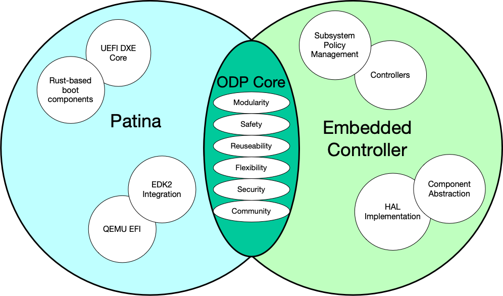
Figure: ODP Architecture Across Domains
The ODP Core expresses a set of shared design patterns – such as modularity, safety, and flexibility – that are applied independently within two distinct ecosystems: Patina (x86 firmware) and Embedded Controller (μC runtime). Each domain develops its own components, tooling, and conventions while adhering to the same architectural principles.
Common Patterns of ODP
While Patina and EC serve different ends of the firmware spectrum, they share a common set of patterns and priorities that define the ODP approach:
- Modularity: ODP components are explicitly modular. Each unit is independently defined and can be composed into larger systems through clearly defined interfaces. This is central to the dependency-injection models used by both Patina and EC’s service registry architecture.
- Safety: Rust’s type system and ownership model are used to enforce memory and concurrency safety at compile time. This baseline ensures that ODP firmware avoids common pitfalls typical of C-based implementations.
- Reusability: Components are designed to be reusable across platforms, configurations, and targets. Traits and message interfaces abstract functionality, enabling code reuse without sacrificing clarity or safety.
- Flexibility: The ODP structure supports adaptation to a wide variety of host platforms and runtime environments. This flexibility allows implementers to scale from minimal EC services up to full boot firmware stacks.
- Community: ODP is built on open standards and community contributions. This encourages collaboration, knowledge sharing, and the evolution of best practices across the ecosystem, which only enhances the robustness of the architecture and its promises of safety and modularity.
The Open Device Partnership is founded more upon alignment than unification and is supported and extended by the principles of a strong Open Source community, where it will expand and evolve.
Patina Framework Architecture
Traditional UEFI architecture describes a series of boot phases that are executed in a specific order to initialize the system and prepare it for use. The Patina framework is designed to fit within this architecture, specifically focusing on the DXE (Driver Execution Environment) phase.
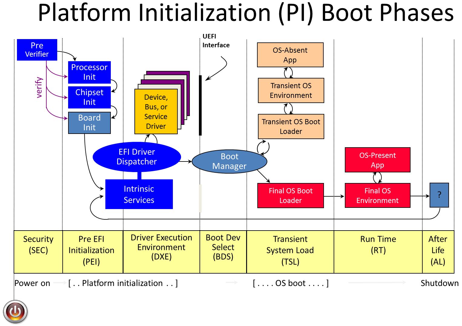
Patina re-imagines the DXE phase as a framework for building modular, reusable components that can be dynamically loaded and executed. This approach allows for greater flexibility and agility in firmware development, enabling developers to create components that can be easily reused across different platforms and configurations.
flowchart TD
    A[UEFI] --> B[Patina Framework]
    B --> C[Component Registration]
    B --> D[EFI Binary Output]
    B --> E[Platform Boot]
    C --> F[Device Drivers]
    E --> G[System Services]
    E --> H[User Applications]
    F --> G
Figure: Patina Framework within UEFI Boot Phases
For architectural details, refer to the Patina DXE Core documentation.
Patina Components
Patina components are built according to Traits and introduced via Dependency Injection (DI) into the Patina framework. This allows for a modular and reusable design that can be easily adapted to different platforms and configurations.
Component Development
Please refer to the Patina documentation for more details, but the basic pseudo-code steps for creating a component are actually pretty simple:
#![allow(unused)]
fn main() {
use log::info;
use patina_sdk::{component::params::Config, error::Result};

#[derive(Default, Clone, Copy)]
pub struct Name(pub &'static str);

pub fn run_test_component(name: Config<Name>) -> Result<()> {
    info!("============= Test Component ===============");
    info!("Hello, {}!", name.0);
    info!("=========================================");
    Ok(())
}
}
One creates a component as a function with parameters that implement the required traits (in this case the Config
#![allow(unused)]
fn main() {
Core::default()
    .with_component(test_component::run_test_component)
    .with_config(test_component::Name("World"))
    .start()
}
What the component actually does is up to the developer, but the structure remains consistent. The component can be as simple or complex as needed, and it can interact with other components through the Patina framework’s messaging system.
Refer to Patina’s component model documentation and the Patina dispatcher documentation for official details on the component model and how to implement components in Patina.
Embedded Controller Architecture
The construction of a typical component under the control of a service subsystem looks as follows:
flowchart LR
    A[Some Service<br><i>Service initiates query</i>]
    B[Subsystem Controller<br><i>Orchestrates component behavior</i>]
    C[Component Trait Interface<br><i>Defines the functional contract</i>]
    D[HAL Implementation<br><i>Implements trait using hardware-specific logic</i>]
    E[EC / Hardware Access<br><i>Performs actual I/O operations</i>]

    A --> B
    B --> C
    C --> D
    D --> E

    subgraph Service Layer
        A
    end

    subgraph Subsystem Layer
        B
    end

    subgraph Component Layer
        C
        D
    end

    subgraph Hardware Layer
        E
    end
When in operation, it conducts its operations in response to message events
sequenceDiagram
    participant Service as Some Service
    participant Controller as Subsystem Controller
    participant Component as Component (Trait)
    participant HAL as HAL (Hardware or Mock)

    Service->>Controller: query_state()
    Note right of Controller: Subsystem logic directs call via trait
    Controller->>Component: get_state()
    Note right of Component: Trait implementation calls into HAL
    Component->>HAL: read_some_level()
    HAL-->>Component: Ok(0)
    Component-->>Controller: Ok(State { value: 0 })
    Controller-->>Service: Ok(State)

    alt HAL returns error
        HAL-->>Component: Err(ReadError)
        Component-->>Controller: Err(SomeError)
        Controller-->>Service: Err(SomeUnavailable)
    end
A core pattern of the ODP architecture is one of Dependency Injection. The service and subsystem Traits define the functional contract of the component, while the HAL implementation provides the hardware-specific logic. This allows for a clear separation of concerns and enables the component to be easily tested and reused across different platforms. Components are eligible to be registered for their subservice if they match the required traits.
flowchart TD
    subgraph Component
        A[Needs Logger and Config]
    end

    subgraph Framework
        B[Provides ConsoleLogger]
        C[Provides NameConfig]
        D[Injects Dependencies]
    end

    B --> D
    C --> D
    D --> A
EC Component Model
A component that implements a specification and depends upon a HAL interface.
flowchart TD
    A[Component]
    B[Specification Trait]
    C[HAL Trait]

    A --> B
    A --> C
A component is housed within a subsystem, which is controlled by a service. The service orchestrates the component’s behavior and manages its lifecycle.
flowchart TD
    A[__Controller__ <br/> Implements Service Interface Trait]
    B[__Device__ <br/> Implements Component Type Trait]
    C[__Component__ <br/> Implements Specification Trait]

    A --> B
    B --> C
Component interactions are generally initiated in response to message events. The controller receives a message, which it routes to the component. The component then calls into the HAL to perform the requested operation.
flowchart TD
    A[__Service Layer__ <br/> e.g. _Controller_]
    B[__Device Layer__ <br/> _Wrapped Component_]
    C[__Component Layer__ <br/> _Handles Message_]

    M["Incoming Message"] --> A
    A -->|calls _handle_| B
    B -->|calls _handle_| C
EC Services Architecture
Communication Pathways
flowchart TD
    A[Host OS or Firmware]
    B[ACPI Interface / Mailbox / HID]
    C[EC Service Dispatcher]
    D[Subsystem Controller - Battery, Thermal, etc.]

    A --> B
    B --> C
    C --> D
Figure: EC Service Entry Points Host platforms interact with EC services through one or more communication pathways. These may include ACPI-defined regions, mailbox protocols, or vendor-defined HID messages. The EC processes these via service dispatch logic.
Messaging Exchange Format (Conceptual)
sequenceDiagram
    participant Host
    participant EC

    Host->>EC: Request {Service ID, Command, Payload}
    EC-->>Host: Response {Status, Data}
Figure: Message Exchange
The diagram above illustrates the basic message handshake.
This table explains the field data exchanged:
Field Description Service ID Identifies target subsystem Command Specific operation to perform Payload Data required for operation Status Result of operation Data Optional result values
Secure and Non-Secure Implementations
In the diagram below, the dark blue sections are those elements that are part of normal (non-secure) memory space and may be called from a service interface directly. As we can see on the Non-Secure side, the ACPI transport channel has access to the EC component implementations either directly or through the FF-A (Firmware Framework Memory Management Protocol).
Secure implementation architecture can be seen in the upcoming Security discussion.
flowchart TD
    A[Untrusted Host OS]
    B[Trusted Runtime Services]
    C[EC Service Gateway]
    D[EC Subsystems]

    A -.->|Filtered Access| C
    B -->|Secure Channel| C
    C --> D
ODP Security Architecture
Whether in the Patina or Embedded Controller domain, ODP’s security architecture is designed to ensure the integrity and trustworthiness of firmware components. This architecture is built upon several key principles:
- Least Privilege: Components operate with the minimum privileges necessary to perform their functions, reducing the risk of unauthorized access or damage.
- Isolation: Components are isolated from one another to prevent unintended interactions and to contain potential security breaches.
- Verification: Components are verified at boot time to ensure they have not been tampered with and that they meet the expected security standards.
- Layered Defense: Security concerns are enforced at multiple levels — bootloader, firmware, EC messaging, and runtime service dispatch.
flowchart TD
    A[Reset Vector / ROM]
    B[Bootloader / Core Root of Trust]
    C[Patina DXE Core]
    D[OS Boot]
    E[EC Runtime]
    F[EC Services]

    A --> B
    B --> C
    C --> D

    B -->|Key Exchange, FFA| E
    E --> F

    subgraph Secure World
        B
        E
    end

    subgraph Non-Secure World
        C
        D
        F
    end
Figure: System Trust Boundaries
The ODP system defines strong isolation between secure and non-secure execution. Firmware integrity is established early and extended to runtime services. EC services may operate in either domain, depending on platform architecture.
| Area | Concerns | Enforced By |
|---|---|---|
| Secure Boot | Root trust, signed firmware, measurement | Bootloader / Patina |
| Firmware Update | Verification, rollback protection | Update agent, signing keys |
| EC Services | Isolation, message auth, FF-A routing | Hafnium, UUID filtering, runtime logic |
Secure Boot Architecture
Secure Boot is a cryptographically enforced boot validation mechanism that ensures each stage of system initialization is authenticated and unmodified. Its goal is to prevent unauthorized firmware or operating systems from executing on the platform.
flowchart TD
    A[__Boot ROM__ <br>Immutable Trust Anchor]
    B[__Bootloader__ <br> - _e.g. BL1, Coreboot_]
    C[__Patina DXE Core__ <br>Signed EFI Binary]
    D[__OS Bootloader__<br>_Optional Verification_]
    E[__Operating System__<br>Signed Kernel and Drivers]

    A --> B
    B --> C
    C --> D
    D --> E
Figure: Secure Boot Chain of Trust
Each stage validates the integrity and authenticity of the next using cryptographic signatures or measured hashes. Patina fits into this chain as the DXE-phase firmware payload, typically signed and validated prior to execution.
Role of Patina in Secure Boot
- The DXE Core produced by Patina is signed and stored as an .efi binary.
- The platform bootloader (coreboot, U-Boot, etc.) or UEFI Secure Boot loader validates the Patina payload before execution.
- Patina itself does not contain its own secure bootloader but is designed to be a signed leaf node in a secure boot chain.
On platforms with measured boot (e.g., DRTM or TPM-backed environments), Patina binaries can also be hashed and extended into a PCR register.
Signature and Validation Workflow
flowchart TD
    A[__Patina EFI Binary__]
    B[__Public Key__ - _in Bootloader_]
    C[__Signature Verification__]
    D[__Execution__]

    A --> C
    B --> C
    C -->|If Valid| D
    C -->|If Invalid| E[Halt / Recovery]
A secure boot process is only one part of the platform’s trust chain. To preserve integrity after boot, Firmware Updates must be signed and verified, and Runtime E access must be validated and isolated.
Secure Firmware Updates
Secure firmware update mechanisms are critical to preserving system trust over time. They prevent unauthorized or malicious firmware from being flashed, and protect the system from rollback to known-vulnerable versions. ODP-based firmware components, including Patina and the EC runtime, support signed and validated update flows.
Update Integrity Requirements
Firmware updates must meet several key integrity requirements:
- Authentication: Updates must be signed by a trusted vendor key.
- Integrity: Payloads must not be tampered with (crytopgraphic hashes are checked).
- Rollback Protection: Systems must prevent downgrading to older, potentially vulnerable firmware versions.
- Isolation: Updates must not interfere with runtime operations, allow modification of unrelated components, or expose sensitive data.
flowchart LR
    A[Host System or Update Agent]
    B[Receives Update Payload]
    C[Verifies Signature]
    D[Checks Version Policy]
    E[Applies Update]
    F[Reboots to New Firmware]

    A --> B --> C --> D --> E --> F
Figure: Generic Secure Update Flow
Update delivery may be initiated by the OS or host firmware. The platform verifies signatures and version constraints before committing the update and restarting the system.
Secure EC Services
flowchart TD
    subgraph Host System
        A1[ACPI Methods]
        A2[ACPI Notification Events]
    end

    subgraph Secure World
        B1["Hafnium (FFA Handler)"]
    end

    subgraph EC
        C1[EC Dispatcher]
        C2[Subsystem Controller]
    end

    A1 -->|"Secure Path (ARM/FFA)"| B1
    A2 -->|Notifications| B1
    B1 -->|Structured Command| C1
    C1 --> C2

    A1 -->|"Non-Secure (x86)"| C1
Figure: Host–EC Communication Paths
The host communicates with the EC via ACPI calls and notification events. On ARM platforms with secure world enforcement, messages are routed through Hafnium via FF-A interfaces. On x86 platforms, communication is direct. The EC dispatcher then forwards commands to appropriate subsystem controllers.
The tracks of ODP
ODP is a comprehensive umbrella addressing a span of firmware concerns:
- Boot Firmware / UEFI (Patina)
- Embedded Controller components and services (EC)
- Security firmware and architecture
Development efforts for these domains are often not performed by the same teams, and these pieces are often built independently of each other and only brought together in the end.
ODP does not usurp this development paradigm but rather empowers it further through the commonality of the Rust language and tools, and through a shared philosophy of modularity and agility.
How to continue with this book
This book is geared to a couple of different distinct audiences. If you are concerned primarily with any one of the particular ‘tracks’ of ODP and are interested in a guide to which ODP repositories are relevant for that track, continue with What is in ODP?
If you are a Firmware Engineer you likely will want to continue following ahead into the hands-on projects for building Embedded Controller components and services, and integrating these into an EC simulation and test application. To continue on this track, simply continue to the next article.
Depending on your interest or role, we offer guided tracks through the documentation:
Subject-based:
-
🏅 Value Proposition Understand the core benefits of ODP, including security, modularity, and cross-domain coherence.
-
🛫 Patina Boot Firmware
Learn to build UEFI firmware with Rust using the Patina framework. -
🔋 Embedded Controller and Services Dive into EC subsystems like battery, charger, and thermal control with real component walkthroughs.
-
🔐 Security Architecture
Explore trusted boot, firmware identity, and the DICE model.
Role-based:
-
🔧 Integrator Discover how to integrate ODP components into larger systems.
-
🧑🤝🧑 Contributor Get involved in the ODP community by contributing code, documentation, or reporting issues.
Technical readers may also be interested in the Specifications section, which provides detailed technical specifications for ODP components and services.
What is in ODP?
There are over 60 repositories that make up the whole of the ODP umbrella. Many of these are simply HAL definitions for particular hardware, but others define the critical business logic and data traits that comprise the portable and modular framework ODP provides. Many of the crates defined by these repositories may be interdependent.
Other repositories represented here define tools and tests that are useful in development.
Patina
| Repository | Description | Tag |
|---|---|---|
| Developing UEFI with Rust | (Document) Overview of ODP Patina and Rust, contribution guide, and build setup. | Patina |
| patina | Library of crates implementing Patina UEFI code. | Patina |
| patina-dxe-core-qemu | Builds .efi image from Patina libraries and local components for QEMU. | Patina |
| patina-qemu | QEMU platform firmware integrating .efi Patina binaries. | Patina |
| patina-readiness-tool | Tests platform readiness for Patina. | Patina |
| patina-fw-patcher | Speeds up incremental firmware build iterations vs. full stuart_build. | Patina |
| patina-mtrr | MTRR (Memory Type Range Register) library for x86_64. | Patina |
| patina-paging | Common paging support for ARM64 and x64. | Patina |
| uefi-corosensei | UEFI fork of corosensei crate. | Patina |
EC
| Repository | Description | Tag |
|---|---|---|
| embedded-services | Service definitions wrapping HAL components. | EC |
| soc-embedded-controller | Demonstration of EC firmware built using ODP components. | EC |
| embedded-batteries | SmartBattery spec traits for HAL abstraction. | EC |
| embedded-sensors | Embedded sensors HAL abstraction. | EC |
| embedded-fans | HAL definition for fan control. | EC |
| embedded-power-sequence | SoC power on/off abstraction. | EC |
| embedded-cfu | Implements Windows CFU commands/responses. | EC |
| embedded-usb-pd | Common types for USB-PD. | EC |
| embedded-mcu | MCU traits and libraries for hardware peripherals. | EC |
| hid-embedded-controller | HID over I2C demo library for ECs. | EC |
| ec-test-app | Test application to exercise EC functionality via ACPI. | EC |
| ffa | FF-A services in Rust for Hafnium. | EC |
| haf-ec-service | Rust EC services for Hafnium. | EC |
| ec-slimloader | Stage-one EC bootloader. | EC |
| ec-slimloader-descriptors | Boot descriptors for multi-image firmware scenarios. | EC |
(plus all drivers, PACs, and HAL crates such as bq24773, bq40z50, tmp108, mec17xx-pac, npcx490m-examples, embassy-*, etc.) | EC |
Security
| Repository | Description | Tag |
|---|---|---|
| rust_crate_audits | Aggregated Rust crate audits. | Security |
Tooling
| Repository | Description | Tag |
|---|---|---|
| odp-utilites | Rust utilities for embedded development. | Tooling |
| systemview-tracing | Adds Segger SystemView tracing to ODP. | Tooling |
| nxp-header | CLI utility for NXP image headers. | Tooling |
How To Build A Modern Laptop using ODP
Modern laptops are far more than a CPU and memory strapped to a motherboard. They are intricate systems where firmware, controllers, and operating systems all work together to deliver reliable behavior under changing conditions: power, thermals, charging, battery health, and more.
In this guide we focus on the Embedded Controller (EC), because it is the orchestrator of many of these dynamics. The EC is where policies for battery charging, fan curves, and system load management come together. It is also where ODP’s modular component model shines: you can construct, swap, and simulate subsystems in a way that is transparent to the host.
Patina, ODP’s Rust-based UEFI implementation, is part of the bigger story. The practical hands-on documentation for building a ready-to-go boot firmware image is not part of this guide, but is available through the Patina resources elsewhere.
What are we setting out to do?
We will not be assembling a physical laptop on your desk. Instead, we will be exploring how a modern laptop could be constructed — piece by piece — using ODP components. Along the way you will:
- Learn how to set up a firmware development environment.
- Construct a virtual EC with battery, charger, and thermal subsystems.
- Experiment with policies that react to simulated events.
- Observe how these policies can be exercised and tested from the outside world.
What might this lead to?
The exercises here will give you working examples of individual components. They also serve as a foundation for something more ambitious: combining these pieces into a real integration, or perhaps even a virtual laptop. With the right emulation, you could connect an EC (real or simulated) to a host via ACPI, layer in Patina firmware, and boot into an operating system that recognizes and uses your virtualized subsystems.
That end-to-end journey is beyond the strict scope of this guide. But it’s the horizon we keep in mind as we explore each step.
Setting up Development
If you are planning on going through these exercises to get a handle on developing components for Patina or the Embedded Controller, you will not need anything more than the Rust toolchain and development tools already described. You can build each of the exercises to construct a component in a non-embedded (std) environment and test on your local machine.
However, if you are planning on building for the virtual laptop project, you will need to set up QEMU as the host for the Patina boot firmware, and for EC Components, you will need a development board where you will target your embedded code to run on as a makeshift Embedded Controller.
Embedded Controller Components
The Embedded Controller orchestrates a number of individual Device Components. Each component is tailored to meet a given subservice feature that is defined by traits. A Device signature that fulfills these traits can be injected as a component into the system in a modular way.
In the following exercises we will build a few such components – Battery, Charger, and Thermal – and learn the patterns for constructing and testing Embedded Controller components that are ready for embedded targeting and integration.
Battery and Power Management
This example shows how to implement a mock battery service as part of the Embedded Controller (EC) power management system.
In this sample, we are going to implement a complete battery service subsystem.
Relevant Repositories
We don’t need to reinvent any wheels here. The ODP resources include ample template code and examples we can refer to for such a task. It is useful to identify which repositories contain these resources:
embedded-services
We’ve touched on this before in Embedded Services, where we examined a Thermal subsystem implementation and explored variations between secure ARM-based and legacy x86_64-based systems.
We’ll return to both of these concepts later. For now, we’ll focus on implementing a Battery subsystem and related Power Policy services. After that, we’ll fold in Thermal support and revisit the secure vs. non-secure implementations.
embedded-batteries
This repository defines the Hardware Abstraction Layer (HAL) for a battery, tailored to the specific IC hardware being targeted. It builds a layered API chain upward, making most of the code portable and reusable across different integrations.
embassy
Although our first exercises will be limited to simple desktop tests, we will then be building for an embedded context and that will require us to use features from Embassy both directly and indirectly.
We’ll begin with the battery service — one of the embedded services — and later return here to integrate our battery into the broader scope of power management.
Goals of the Battery Component Example
In this example we will be constructing a fucntioning battery component.
The battery itself will be a virtual battery - no hardware required - and the behavioral aspects of it will be simulated. We will, however, discuss what one would do to implement actual battery hardware control in a HAL layer, which is the only fundamental difference between the virtual and real-world manifestations of this component.
In this example, we will:
- Define the Traits of the battery component as defined by the industry standard Smart Battery Specification (SBS)
- Identify the hardware actions that fulfill these traits
- Define the HAL traits to match these hardware actions
- Implement the HAL traits to hardware access (or define mocks for a virtual example)
- Wrap this simple Traits implementation into a Device for service insertion
- Provide the service layer and insert the device into it
- Test the end result with unit tests and simple executions
How we will build the Battery Component
Like most components, the battery starts with a definition, or specification. Most common components have industry-standard specifications associated with them. For the battery, we have the Smart Battery Specification (SBS).
The Smart Battery
Batteries are ubiquitous in today’s portable devices. With many types of batteries serving various applications and provided by many vendors, the Smart Battery Data Specification offers a standard to normalize this diversity.
Published by the Smart Battery System Implementers Forum (SBS-IF), this specification defines both electrical characteristics and — more importantly for us — the data and communication semantics of battery state.
Let’s explore how this specification informs our implementation.
Battery Information
A battery provides dynamic information (e.g., remaining charge), static metadata (e.g., make/model/serial/version), and operational parameters (e.g., recommended charge voltage/current).
As explored in …, some of this information is exposed through direct hardware interfaces (e.g., GPIO or MMIO), while others originate from firmware logic or are derived dynamically.
Batteries typically report their state over a bus when queried and may also broadcast alarms when thresholds are breached.
The SBS specification outlines these functions that a smart battery should implement. These define a consistent set of data points and behaviors that other power management components can rely on:
ManufacturerAccess– Optional, manufacturer-specific 16-bit value.RemainingCapacityAlarm– Battery capacity threshold at which an alert should be raised.RemainingTimeAlarm– Estimated time remaining before an alert should be raised.BatteryMode– Flags indicating operational states or supported features.AtRate– Charging/discharging rate used in subsequent time estimations.AtRateTimeToFull– Time to full charge at the given rate.AtRateTimeToEmpty– Time to depletion at the given rate.AtRateTimeOK– Whether the battery can sustain the given rate for at least 10 seconds.Temperature– Battery temperature.Voltage– Battery voltage.Current– Charge or discharge current.AverageCurrent– One-minute rolling average of current.MaxError– Expected error margin in charge calculations.RelativeStateOfCharge– % of full charge capacity remaining.AbsoluteStateOfCharge– % of design capacity remaining.RemainingCapacity– In mAh or Wh, based on a capacity mode flag.FullChargeCapacity– In mAh or Wh, based on capacity mode.RunTimeToEmpty– Estimated minutes remaining.AverageTimeToEmpty– One-minute average of minutes to empty.AverageTimeToFull– One-minute average of minutes to full charge.BatteryStatus– Flags indicating current state conditions.CycleCount- Number of cycles (a measure of wear). A cycle is the amount of discharge approximately equal to the value of the DesignCapacity.DesignCapacity- The theoretical capacity of a new battery pack.DesignVoltage- The theoretical voltage of a new battery pack.SpecificationInfo- Version and scaling specification infoManufactureDate- The data of manufacture as a bit-packed integerSerialNumber- the manufacturer assigned serial number of this battery pack.ManufacturerName- Name of the manufacturerDeviceName- Name of battery model.DeviceChemistry- String defining the battery chemical typeManufacturerData- (optional) proprietary manufacturer data.
Please refer to the actual specification for details. For example, functions referring to capacity may report in either current (mAh) or wattage (Wh) depending upon the current state of the CAPACITY_MODE flag (found in BatteryMode).
Some systems may support removable batteries, and such conditions must be accounted for in those designs.
In the next steps, we will use the ODP published crates that expose this SBS definition as a Trait and build our implementation on top of that starting point.
We will implement the mock values and behaviors of our simulated battery - instead of defining and building a HAL layer - and then we will walk through the process of attaching this component definition to a Device wrapper and registering it as a component with a Controller that can be manipulated by a service layer - in this case, the Power Policy Service.
Battery component Diagrams
The construction of a component such as our battery looks as follows.
flowchart TD
    A[Power Policy Service<br><i>Service initiates query</i>]
    B[Battery Subsystem Controller<br><i>Orchestrates component behavior</i>]
    C[Battery Component Trait Interface<br><i>Defines the functional contract</i>]
    D[Battery HAL Implementation<br><i>Implements trait using hardware-specific logic</i>]
    E[EC / Hardware Access<br><i>Performs actual I/O operations</i>]

    A --> B
    B --> C
    C --> D
    D --> E

    subgraph Service Layer
        A
    end

    subgraph Subsystem Layer
        B
    end

    subgraph Component Layer
        C
        D
    end

    subgraph Hardware Layer
        E
    end
When in operation, it conducts its operations in response to message events
sequenceDiagram
    participant Service as Power Policy Service
    participant Controller as Battery Subsystem Controller
    participant Component as Battery Component (Trait)
    participant HAL as Battery HAL (Hardware or Mock)

    Service->>Controller: query_battery_state()
    Note right of Controller: Subsystem logic directs call via trait
    Controller->>Component: get_battery_state()
    Note right of Component: Trait implementation calls into HAL
    Component->>HAL: read_charge_level()
    HAL-->>Component: Ok(82%)
    Component-->>Controller: Ok(BatteryState { charge_pct: 82 })
    Controller-->>Service: Ok(BatteryState)

    alt HAL returns error
        HAL-->>Component: Err(ReadError)
        Component-->>Controller: Err(BatteryError)
        Controller-->>Service: Err(BatteryUnavailable)
    end
Building the component
Let’s get started on building our battery implementation
A Mock Battery
In our example, we will build the full functionality of our component in a standard local-computer development environment.
This allows us to begin development without worrying about hardware complications while still implementing nearly all of the system’s behavior. In the end, we will have a fully functional—albeit artificial—battery subsystem.
Once complete, our battery implementation is ready to be migrated, flashed and tested on target embedded hardware, where it should behave identically as a virtual, and/or able to be integrated to actual battery hardware with minor HAL layer implementations that replace our virtual layer here.
In our example case, our battery will remain virtual, with simulated physical behavior.
A Mock Battery Project
In the previous section, we saw how the Smart Battery Specification (SBS) defines a set of functions that a Smart Battery service should implement.
In the next pages, we are going to review how these traits are defined in Rust within the embedded-services repository, and we are going to import these structures into our own workspace as we build our mock battery. In subsequent steps we’ll connect the battery into the supporting upstream EC service framework.
Setting up for development
We are going to create a project space that contains a folder for our battery code, and the dependent repository clones.
So, start by finding a suitable location on your local computer and create the workpace:
mkdir battery_project
cd battery_project
git init
This will create a workspace root for us and establish it as a git repository (not attached).
Now, we are going to bring the embedded-batteries directory into our workspace and build the crates it exports.
(from the battery_project directory):
git submodule add https://github.com/OpenDevicePartnership/embedded-batteries
The embedded-batteries repository has the subsystem service definitions for the battery defined in both
embedded-batteries and embedded-batteries-async crates. We are going to use the async variant here because this is required when attaching
later to the Controller, which we will attach our battery implementation into the larger service framework.
Now, we can create our project space and start our own work. Within the battery_project directory, create a folder named mock_battery and give it this project structure:
mock_battery/
  src/
   - lib.rs
   - mock_battery.rs
  Cargo.toml

Cargo.toml
note there are two Cargo.toml files here. One is within the battery_project root folder and the other is at the root of mock_battery. The mock_battery.rs file resides within the mock_battery/src directory.
The contents of the battery_project/Cargo.toml file should contain:
[workspace]
resolver = "2"
members = [
    "mock_battery"
]
and the contents of the battery_project/mock_battery/Cargo.toml file should be set to:
[package]
name = "mock_battery"
version = "0.1.0"
edition = "2024"

[dependencies]
embedded-batteries-async = { path = "../embedded-batteries/embedded-batteries-async" }
This structure and the Cargo.toml definitions just define a minimal skeleton for the dependencies we will be adding to as we continue to build our mock battery implementation and work it into the larger ODP framework.
The lib.rs file is used to tell Rust which modules are part of the project. Set it’s contents to:
#![allow(unused)]
fn main() {
pub mod mock_battery;
}
the mock_battery.rs file can be empty for now. We will define its contents in the next section.
Using the ODP repositories for defined Battery Traits
In the previous step we set up our project workspace so that we can import from the ODP framework. In this step we will define the traits that our mock battery will expose.
Implementing the defined traits
From the overview discussion you will recall that the SBS specification defines the Smart Battery with a series of functions that will return required data in expected ways. Not surprisingly, then, we will find that the embedded-batteries crate we have imported defines these functions as traits to a SmartBattery trait. If you are new to Rust, recall that if this were, say, C++ or Java, we would call this the SmartBattery class, or an interface. These are almost interchangeable terms, but there are differences. See this definition for more detail on that.
If we look through the embedded-batteries repository, we will see the SmartBattery trait defines the same functions we saw in the specification (except for the optional proprietary manufacturer facilitation).
So our job now is to implement these functions with data that comes from our battery - our Mock Battery.
We’ll start off our mock_battery.rs file with this:
#![allow(unused)]
fn main() {
use embedded_batteries_async::smart_battery::{
    SmartBattery, CapacityModeValue, CapacityModeSignedValue, BatteryModeFields,
    BatteryStatusFields, SpecificationInfoFields, ManufactureDate, ErrorType,
    Error, ErrorKind
};

#[derive(Debug)]
pub enum MockBatteryError {}

impl core::fmt::Display for MockBatteryError {
    fn fmt(&self, f: &mut core::fmt::Formatter<'_>) -> core::fmt::Result {
        write!(f, "MockBatteryError")
    }
}

impl Error for MockBatteryError {
    fn kind(&self) -> ErrorKind {
        ErrorKind::Other
    }
}

pub struct MockBattery;

impl ErrorType for MockBattery {
    type Error = MockBatteryError;
}

impl SmartBattery for MockBattery {
    async fn remaining_capacity_alarm(&mut self) -> Result<CapacityModeValue, Self::Error> {
        Ok(CapacityModeValue::MilliAmpUnsigned(0))
    }

    async fn set_remaining_capacity_alarm(&mut self, _val: CapacityModeValue) -> Result<(), Self::Error> {
        Ok(())
    }

    async fn remaining_time_alarm(&mut self) -> Result<u16, Self::Error> {
        Ok(0)
    }

    async fn set_remaining_time_alarm(&mut self, _val: u16) -> Result<(), Self::Error> {
        Ok(())
    }

    async fn battery_mode(&mut self) -> Result<BatteryModeFields, Self::Error> {
        Ok(BatteryModeFields::default())
    }

    async fn set_battery_mode(&mut self, _val: BatteryModeFields) -> Result<(), Self::Error> {
        Ok(())
    }

    async fn at_rate(&mut self) -> Result<CapacityModeSignedValue, Self::Error> {
        Ok(CapacityModeSignedValue::MilliAmpSigned(0))
    }

    async fn set_at_rate(&mut self, _val: CapacityModeSignedValue) -> Result<(), Self::Error> {
        Ok(())
    }

    async fn at_rate_time_to_full(&mut self) -> Result<u16, Self::Error> {
        Ok(0)
    }

    async fn at_rate_time_to_empty(&mut self) -> Result<u16, Self::Error> {
        Ok(0)
    }

    async fn at_rate_ok(&mut self) -> Result<bool, Self::Error> {
        Ok(true)
    }

    async fn temperature(&mut self) -> Result<u16, Self::Error> {
        Ok(2950) // 29.5°C in deciKelvin
    }

    async fn voltage(&mut self) -> Result<u16, Self::Error> {
        Ok(7500) // mV
    }

    async fn current(&mut self) -> Result<i16, Self::Error> {
        Ok(1500)
    }

    async fn average_current(&mut self) -> Result<i16, Self::Error> {
        Ok(1400)
    }

    async fn max_error(&mut self) -> Result<u8, Self::Error> {
        Ok(1)
    }

    async fn relative_state_of_charge(&mut self) -> Result<u8, Self::Error> {
        Ok(88)
    }

    async fn absolute_state_of_charge(&mut self) -> Result<u8, Self::Error> {
        Ok(85)
    }

    async fn remaining_capacity(&mut self) -> Result<CapacityModeValue, Self::Error> {
        Ok(CapacityModeValue::MilliAmpUnsigned(4200))
    }

    async fn full_charge_capacity(&mut self) -> Result<CapacityModeValue, Self::Error> {
        Ok(CapacityModeValue::MilliAmpUnsigned(4800))
    }

    async fn run_time_to_empty(&mut self) -> Result<u16, Self::Error> {
        Ok(60)
    }

    async fn average_time_to_empty(&mut self) -> Result<u16, Self::Error> {
        Ok(75)
    }

    async fn average_time_to_full(&mut self) -> Result<u16, Self::Error> {
        Ok(30)
    }

    async fn charging_current(&mut self) -> Result<u16, Self::Error> {
        Ok(2000)
    }

    async fn charging_voltage(&mut self) -> Result<u16, Self::Error> {
        Ok(8400)
    }

    async fn battery_status(&mut self) -> Result<BatteryStatusFields, Self::Error> {
        Ok(BatteryStatusFields::default())
    }

    async fn cycle_count(&mut self) -> Result<u16, Self::Error> {
        Ok(100)
    }

    async fn design_capacity(&mut self) -> Result<CapacityModeValue, Self::Error> {
        Ok(CapacityModeValue::MilliAmpUnsigned(5000))
    }

    async fn design_voltage(&mut self) -> Result<u16, Self::Error> {
        Ok(7800)
    }

    async fn specification_info(&mut self) -> Result<SpecificationInfoFields, Self::Error> {
        Ok(SpecificationInfoFields::default())
    }

    async fn manufacture_date(&mut self) -> Result<ManufactureDate, Self::Error> {
        let mut date = ManufactureDate::new();
        date.set_day(1);
        date.set_month(1);
        date.set_year(2025 - 1980); // must use offset from 1980

        Ok(date)
    }

    async fn serial_number(&mut self) -> Result<u16, Self::Error> {
        Ok(12345)
    }

    async fn manufacturer_name(&mut self, buf: &mut [u8]) -> Result<(), Self::Error> {
        let name = b"MockBatteryCorp\0"; // Null-terminated string
        buf[..name.len()].copy_from_slice(name);
        Ok(())
    }

    async fn device_name(&mut self, buf: &mut [u8]) -> Result<(), Self::Error> {
        let name = b"MB-4200\0";
        buf[..name.len()].copy_from_slice(name);
        Ok(())
    }

    async fn device_chemistry(&mut self, buf: &mut [u8]) -> Result<(), Self::Error> {
        let name = b"LION\0";   // Null-terminated 5-byte string
        buf[..name.len()].copy_from_slice(name);
        Ok(())
    }
}
}
Yes, that’s a bit long, but it’s not particularly complex. We’ll unpack what all this is in a moment. For now, let’s verify this Rust code is valid and that we’ve imported from the ODP repository properly.
Type
cargo build
at the project root. This should build without error.
What’s in there
The code in mock_battery.rs starts out with a use statement that imports what we will need from the embedded-batteries_async::smart_battery crate.
The next section defines a simple custom error type for use in our mock battery implementation. This MockBatteryError enum currently has no variants — it serves as a placeholder that allows our code to conform to the expected error traits used by the broader embedded_batteries framework.
By implementing core::fmt::Display, we ensure that error messages can be printed in a readable form (here, just “MockBatteryError”). Then, by implementing the embedded_batteries::smart_battery::Error trait, we allow this error to be returned in contexts where the smart battery interface expects a well-formed error object. The .kind() method returns ErrorKind::Other to indicate a generic error category.
This scaffolding allows our mock implementation to slot into the service framework cleanly, even if the actual logic is still forthcoming.
Finally, we get to the SmartBattery implementation for our MockBattery. As you might guess, this simply implements each of the functions of the trait as declared, by simply returning an arbitrary representative return value for each. We’ll make these values more meaningful in the next step, but for now, it’s pretty minimalist.
Now to expose this to the service
We have defined the battery traits and given our simulated placeholder values for our mock battery here. If we were implementing a real battery, the process would follow the same pattern except that instead of the literal values we’ve assigned, we would call upon our Hardware Abstraction Layer (HAL) implementation modules to pull these values from the actual hardware circuitry, per manufacturer design (i.e. GPIO or MMIO). But before any of this is useful, it needs to be exposed to the service layer. In an upcoming step, we’ll do a simple test that shows we can expose these values, and then we’ll implement the service layer that conveys these up the chain in response to service messages.
A Virtual Battery
It bears repeating that the outcome of this exercise will be a virtual battery, and not an attachment to real battery hardware.
We are going to construct a virtual battery simulator in this step, but this is a good time to note what we would be doing instead if we were working with real battery hardware at this point.
Implementing a HAL layer
In our virtual Mock Battery, we will not be attaching to any actual hardware. But if we were, this would be the place to do it.
A brief overview of what these steps would be include:
- Consulting the specifications of our hardware to explore its features
- Determine which of these features would be necessary to fulfill each trait from the SBS specification we wish to implement
- Define the traits that name these features or feature sequences.
- Implement these traits in hardware (GPIO / MMIO, etc)
- Use this to fulfill the SBS traits for the values required.
For our mock battery, we will simply return coded values for the SBS traits directly.
The Virtual Battery state machine
Instead of a HAL layer, we will construct a battery that operates entirely through software. This will be a state machine with functions to compute values and simulate behavior over time that is consistent with its real-world counterpart.
This may not be the most sophisticated or comprehensive battery simulator one could construct, but it will be more than sufficient for our purposes.
Create a file named virtual_battery.rs and give it these initial contents:
#![allow(unused)]
fn main() {

use embedded_batteries_async::smart_battery::{
    BatteryModeFields, BatteryStatusFields,
    SpecificationInfoFields, ManufactureDate,
    CapacityModeSignedValue, CapacityModeValue,
    ErrorCode
};

const STARTING_RSOC_PERCENT:u8 = 100;
const STARTING_ASOC_PERCENT:u8 = 100;
const STARTING_REMAINING_CAP_MAH:u16 = 4800;
const STARTING_FULL_CAP_MAH:u16 = 4800;
const STARTING_VOLTAGE_MV:u16 = 4200;
const STARTING_TEMPERATURE_DECIKELVINS:u16 = 2982; // 25 dec C.
const STARTING_DESIGN_CAP_MAH:u16 = 5000;
const STARTING_DESIGN_VOLTAGE_MV:u16 = 7800;


use crate::mock_battery::MockBatteryError;

/// Represents the internal, simulated state of a battery
#[derive(Debug, Clone)]
pub struct VirtualBatteryState {
    pub voltage_mv: u16,
    pub current_ma: i16,
    pub avg_current_ma: i16,
    pub temperature_dk: u16,
    pub relative_soc_percent: u8,
    pub absolute_soc_percent: u8,
    pub remaining_capacity_mah: u16,
    pub full_charge_capacity_mah: u16,
    pub runtime_to_empty_min: u16,
    pub avg_time_to_empty_min: u16,
    pub avg_time_to_full_min: u16,
    pub cycle_count: u16,
    pub design_capacity_mah: u16,
    pub design_voltage_mv: u16,
    pub battery_mode: BatteryModeFields,
    pub at_rate: CapacityModeSignedValue,
    pub remaining_capacity_alarm: CapacityModeValue,
    pub remaining_time_alarm_min: u16,
    pub at_rate_time_to_full: u16,
    pub at_rate_time_to_empty: u16,
    pub at_rate_ok: bool,
    pub max_error: u8,
    pub battery_status: BatteryStatusFields,
    pub specification_info: SpecificationInfoFields,
    pub serial_number: u16,
}

impl VirtualBatteryState {
    /// Create a fully charged battery with default parameters
    pub fn new_default() -> Self {
        let mut battery = Self {
            relative_soc_percent: STARTING_RSOC_PERCENT,
            absolute_soc_percent: STARTING_ASOC_PERCENT,
            remaining_capacity_mah: STARTING_REMAINING_CAP_MAH,
            full_charge_capacity_mah: STARTING_FULL_CAP_MAH,
            design_capacity_mah: STARTING_DESIGN_CAP_MAH,
            design_voltage_mv: STARTING_DESIGN_VOLTAGE_MV,
            voltage_mv: 0,
            temperature_dk: 0,
            at_rate_time_to_full: 0,
            at_rate_time_to_empty: 0,
            at_rate_ok: false,
            max_error: 1,
            battery_status: {
                let mut bs = BatteryStatusFields::new();
                bs.set_error_code(ErrorCode::Ok);
                bs
            },
            specification_info: SpecificationInfoFields::from_bits(0x0011),
            serial_number: 0x0102,
            current_ma: 0,
            avg_current_ma: 0,
            runtime_to_empty_min: 0,
            avg_time_to_empty_min: 0,
            avg_time_to_full_min: 0,
            cycle_count: 0,
            battery_mode: BatteryModeFields::default(),
            at_rate: CapacityModeSignedValue::MilliAmpSigned(0),
            remaining_capacity_alarm: CapacityModeValue::MilliAmpUnsigned(0),
            remaining_time_alarm_min: 0

        };
        battery.reset();
        battery
    }

    /// Advance the battery simulation by one tick (e.g., 1 second)
    pub fn tick(
        &mut self,
        charger_current: u16,
        multiplier:f32
    ) {

        // 1. Update remaining capacity
        let delta_f = (self.current_ma as f32 / 3600.0) * multiplier; // control speed of simulation
        let delta = delta_f.round() as i32;
        let new_remaining = (self.remaining_capacity_mah as i32 + delta)
            .clamp(0, self.full_charge_capacity_mah as i32) as u16;

        // 2. Detect charge-to-discharge crossover for cycle tracking
        if self.current_ma < 0 && self.remaining_capacity_mah > new_remaining && new_remaining == 0 {
            self.cycle_count += 1;
        }

        self.remaining_capacity_mah = new_remaining;

        // 3. Recalculate voltage
        self.voltage_mv = self.estimate_voltage();

        // 4. Adjust current for charging
        if charger_current > 0 {
            self.current_ma = charger_current as i16 - self.current_ma;
        }

        // 5. Adjust average current toward current_ma
        self.avg_current_ma = ((self.avg_current_ma as i32 * 7 + self.current_ma as i32) / 8) as i16;

        // 6. Simulate temp change
        let temp = self.temperature_dk as i32 + self.estimate_temp_change() as i32;
        self.temperature_dk = temp.clamp(0, u16::MAX as i32) as u16;

        // 7. State of Charge updates
        self.relative_soc_percent = ((self.remaining_capacity_mah as f32 / self.full_charge_capacity_mah as f32) * 100.0).round() as u8;
        self.absolute_soc_percent = self.relative_soc_percent.saturating_sub(3); // Or another logic

    }


    /// Estimate voltage based on SoC
    fn estimate_voltage(&self) -> u16 {
        let soc = self.remaining_capacity_mah as f32 / self.full_charge_capacity_mah as f32;
        let min_v = 3000.0;
        let max_v = 4200.0;
        (min_v + (max_v - min_v) * soc) as u16
    }

    /// Simple model for temperature change under load (in deciKelvins)
    fn estimate_temp_change(&self) -> i8 {
        if self.current_ma.abs() > 1000 {
            1 // heating up
        } else if self.temperature_dk > 2982 { // 25 deg C = 2982 DeciKelvins
            -1 // cooling down toward idle
        } else {
            0 // stable
        }
    }

    pub fn time_to_empty_minutes(&self) -> u16 {
        if self.current_ma < 0 {
            ((self.remaining_capacity_mah as i32 * 60) / -self.current_ma as i32)
                .clamp(0, u16::MAX as i32) as u16
        } else {
            u16::MAX
        }
    }

    pub fn time_to_full_minutes(&self) -> u16 {
        if self.current_ma > 0 {
            (((self.full_charge_capacity_mah - self.remaining_capacity_mah) as i32 * 60) / self.current_ma as i32)
                .clamp(0, u16::MAX as i32) as u16
        } else {
            u16::MAX
        }
    }

    /// Set the current draw (- discharge, + charge)
    pub fn set_current(&mut self, current_ma: i16) {
        self.current_ma = current_ma;
    }

    /// Reset to fully charged, idle
    pub fn reset(&mut self) {
        self.remaining_capacity_mah = self.full_charge_capacity_mah;
        self.voltage_mv = STARTING_VOLTAGE_MV;
        self.temperature_dk = STARTING_TEMPERATURE_DECIKELVINS;
        self.current_ma = 0;
        self.avg_current_ma = 0;
        self.cycle_count = 0;
        self.battery_mode = BatteryModeFields::default();
        self.at_rate = CapacityModeSignedValue::MilliAmpSigned(0);
        self.remaining_capacity_alarm = CapacityModeValue::MilliAmpUnsigned(0);
        self.remaining_time_alarm_min = 0;
    }

    pub fn manufacture_date(&mut self) -> Result<ManufactureDate, MockBatteryError> {
        let mut date = ManufactureDate::new();
        date.set_day(1);
        date.set_month(1);
        date.set_year(2025 - 1980); // must use offset from 1980
        Ok(date)
    }

    pub fn manufacturer_name(&mut self, buf: &mut [u8]) -> Result<(), MockBatteryError> {
        let name = b"MockBatteryCorp\0"; // Null-terminated string
        buf[..name.len()].copy_from_slice(name);
        Ok(())
    }

    pub fn device_name(&mut self, buf: &mut [u8]) -> Result<(), MockBatteryError> {
        let name = b"MB-4200\0";
        buf[..name.len()].copy_from_slice(name);
        Ok(())
    }

    pub fn device_chemistry(&mut self, buf: &mut [u8]) -> Result<(), MockBatteryError> {
        let name = b"LION\0";   // Null-terminated 5-byte string
        buf[..name.len()].copy_from_slice(name);
        Ok(())
    }

}

}
Understanding the virtual battery
What we’ve done here is to define a virtual battery as a set of states. These coincide with the values we will need from the MockBattery to satisfy the SmartBattery traits.
We initialize our virtual battery with some constant starting values, and include a reset function that sets the values back to a fully charged, idle state. We offer some helper functions to return some of the dynamic value computations and to relay constant string values.
Of most interest, however, is perhaps the tick() function that controls the simulation.
Here, the caller passes in a multiplier value to control how fast the simulation runs (1x == 1 simulated second per tick).
From this delta, the effects of current draw or charge on the battery reserves and its temperature are computed and
the corresponding states are updated.
Add to lib.rs
We need to make this virtual_battery module visible to the rest of the project, so add it to your lib.rs file as so:
#![allow(unused)]
fn main() {
pub mod mock_battery;
pub mod virtual_battery;
}
Attaching to MockBattery
Now we are going to attach our virtual battery to our MockBattery construction so that it can implement the SmartBattery traits by calling upon our VirtualBatteryState.
Edit your mock_battery.rs file.
At the top, add these imports:
#![allow(unused)]
fn main() {
use crate::virtual_battery::VirtualBatteryState;
use embassy_sync::blocking_mutex::raw::ThreadModeRawMutex;
use embassy_sync::mutex::Mutex;
}
This will give us access to our virtual battery construction and supply the necessary thread-safe wrappers we will need to access it.
We need to update our MockBattery to accommodate an inner VirtualBatteryState property.
Replace the line that currently reads
#![allow(unused)]
fn main() {
pub struct MockBattery;
}
With this block of code instead:
#![allow(unused)]
fn main() {
pub struct MockBattery {
    pub state: Mutex<ThreadModeRawMutex, VirtualBatteryState>,
}

impl MockBattery {
    pub fn new() -> Self {
        Self {
            state: Mutex::new(VirtualBatteryState::new_default()),
        }
    }
}

}
Now we can proceed to replace the current placeholder implementations of the SmartBattery traits.
To do this, we will be changing the function signature patterns from
#![allow(unused)]
fn main() {
async fn function_name(&mut self) -> Result<(), Self:Error>
}
to
#![allow(unused)]
fn main() {
fn function_name(&mut self) -> impl Future<Output = Result<(), Self::Error>>
}
This is in fact a valid replacement that satisfies the trait requirement because although we are not implementing an async function, we are implementing one that returns a Future, which amounts to the same thing. But it is necessary to do here because we are capturing shared state behind a mutex, which introduces constraints that conflict with the way async fn in trait implementations is normally handled. By returning a Future explicitly and using an async move block, we gain the flexibility needed to safely lock and use that shared state within the method, while still satisfying the trait.
Why can’t we just use
async fn?While the
SmartBatterytrait defines its methods usingasync fn, and our earlier implementation used that form successfully, it no longer works once we introduce shared mutable state behind aMutex. Here’s why:
async fnin a trait impl “de-sugars” to a fixed, compiler-generated Future type.- This future type must be safely transferrable and nameable in the trait system.
- When the body of the
async fncaptures a value likeself.state.lock().await, it may no longer satisfy required bounds likeSend.- This is especially true when using
embassy_sync::Mutex, which is designed for embedded systems and is notSend.- As a result, the compiler refuses the
async fnbecause it cannot produce a compatible future that satisfies the trait’s expectations.☞ The solution is to return a
Futureexplicitly:
- This allows us to construct the future manually using an
async moveblock.- We can safely capture non-
Sendvalues inside this block (such as a mutex guard).- It also avoids lifetime or type inference issues that might arise from compiler-generated future types in trait contexts.
This pattern is not only more flexible but necessary whenever your async code interacts with embedded, single-threaded, or non-
Sendsystems—like those commonly used withno_stdor simulated devices.
With this in mind, we can then implement calls into our VirtualBatteryState by following a pattern such as the one exhibited here:
#![allow(unused)]
fn main() {
    fn voltage(&mut self) -> impl Future<Output = Result<u16, Self::Error>> {
        let state = &self.state;
        async move {
            let lock = state.lock().await;
            Ok(lock.voltage_mv)
        }
    }
}
Where we obtain access to our VirtualBatteryState property and then use async move to obtain a mutex lock for thread safety, and then return the value from the locked state as a Result.
A completed integration
When we repeat that pattern of integration for each of the SmartBattery traits, the end result looks like this:
#![allow(unused)]
fn main() {
impl SmartBattery for MockBattery {
    fn remaining_capacity_alarm(&mut self) -> impl Future<Output = Result<CapacityModeValue, Self::Error>> {
        let state = &self.state;
        async move {
            let lock = state.lock().await;
            Ok(lock.remaining_capacity_alarm)
        }
    }

    fn set_remaining_capacity_alarm(&mut self, val: CapacityModeValue) -> impl Future<Output = Result<(), Self::Error>> {
        let state = &self.state;
        async move {
            let lock = &mut state.lock().await;
            lock.remaining_capacity_alarm = val;
            Ok(())
        }
    }

    fn remaining_time_alarm(&mut self) -> impl Future<Output = Result<u16, Self::Error>> {
        let state = &self.state;
        async move {
            let lock = state.lock().await;
            Ok(lock.remaining_time_alarm_min)
        }
    }

    fn set_remaining_time_alarm(&mut self, val: u16) -> impl Future<Output = Result<(), Self::Error>> {
        let state = &self.state;
        async move {
            let lock = &mut state.lock().await;
            lock.remaining_time_alarm_min = val;
            Ok(())
        }
    }

    fn battery_mode(&mut self) -> impl Future<Output = Result<BatteryModeFields, Self::Error>> {
        let state = &self.state;
        async move {
            let lock = state.lock().await;
            Ok(lock.battery_mode)
        }
    }

    fn set_battery_mode(&mut self, val: BatteryModeFields) -> impl Future<Output = Result<(), Self::Error>> {
        let state = &self.state;
        async move {
            let lock = &mut state.lock().await;
            lock.battery_mode = val;
            Ok(())
        }
    }

    fn at_rate(&mut self) -> impl Future<Output = Result<CapacityModeSignedValue, Self::Error>> {
        let state = &self.state;
        async move {
            let lock = state.lock().await;
            Ok(lock.at_rate)
        }
    }

    fn set_at_rate(&mut self, val: CapacityModeSignedValue) -> impl Future<Output = Result<(), Self::Error>> {
        let state = &self.state;
        async move {
            let lock = &mut state.lock().await;
            lock.at_rate = val;
            Ok(())
        }
    }

    fn at_rate_time_to_full(&mut self) -> impl Future<Output = Result<u16, Self::Error>> {
        let state = &self.state;
        async move {
            let lock = state.lock().await;
            Ok(lock.at_rate_time_to_full)
        }
    }

    fn at_rate_time_to_empty(&mut self) -> impl Future<Output = Result<u16, Self::Error>> {
        let state = &self.state;
        async move {
            let lock = state.lock().await;
            Ok(lock.at_rate_time_to_empty)
        }
    }

    fn at_rate_ok(&mut self) -> impl Future<Output = Result<bool, Self::Error>> {
        let state = &self.state;
        async move {
            let lock = state.lock().await;
            Ok(lock.at_rate_ok)
        }
    }

    fn temperature(&mut self) -> impl Future<Output = Result<u16, Self::Error>> {
        let state = &self.state;
        async move {
            let lock = state.lock().await;
            Ok(lock.temperature_dk)
        }
    }

    fn voltage(&mut self) -> impl Future<Output = Result<u16, Self::Error>> {
        let state = &self.state;
        async move {
            let lock = state.lock().await;
            Ok(lock.voltage_mv)
        }
    }

    fn current(&mut self) -> impl Future<Output = Result<i16, Self::Error>> {
        let state = &self.state;
        async move {
            let lock = state.lock().await;
            Ok(lock.current_ma)
        }
    }

    fn average_current(&mut self) -> impl Future<Output = Result<i16, Self::Error>> {
        let state = &self.state;
        async move {
            let lock = state.lock().await;
            Ok(lock.avg_current_ma)
        }
    }

    fn max_error(&mut self) -> impl Future<Output = Result<u8, Self::Error>> {
        let state = &self.state;
        async move {
            let lock = state.lock().await;
            Ok(lock.max_error)
        }
    }

    fn relative_state_of_charge(&mut self) -> impl Future<Output = Result<u8, MockBatteryError>> {
        let state = &self.state;
        async move {
            let lock = state.lock().await;
            Ok(lock.relative_soc_percent)
        }
    }

    fn absolute_state_of_charge(&mut self) -> impl Future<Output = Result<u8, MockBatteryError>> {
        let state = &self.state;
        async move {
            let lock = state.lock().await;
            Ok(lock.absolute_soc_percent)
        }
    }

    fn remaining_capacity(&mut self) -> impl Future<Output = Result<CapacityModeValue, Self::Error>> {
        let state = &self.state;
        async move {
            let lock = state.lock().await;
            Ok(CapacityModeValue::MilliAmpUnsigned(lock.remaining_capacity_mah))
        }
    }

    fn full_charge_capacity(&mut self) -> impl Future<Output = Result<CapacityModeValue, Self::Error>> {
        let state = &self.state;
        async move {
            let lock = state.lock().await;
            Ok(CapacityModeValue::MilliAmpUnsigned(lock.full_charge_capacity_mah))
        }
    }

    fn run_time_to_empty(&mut self) -> impl Future<Output = Result<u16, Self::Error>> {
        let state = &self.state;
        async move {
            let lock = state.lock().await;
            Ok(lock.time_to_empty_minutes())
        }
    }

    fn average_time_to_empty(&mut self) -> impl Future<Output = Result<u16, Self::Error>> {
        let state = &self.state;
        async move {
            let lock = state.lock().await;
            Ok(lock.avg_time_to_empty_min)
        }
    }

    fn average_time_to_full(&mut self) -> impl Future<Output = Result<u16, Self::Error>> {
        let state = &self.state;
        async move {
            let lock = state.lock().await;
            Ok(lock.avg_time_to_full_min)
        }
    }

    fn charging_current(&mut self) -> impl Future<Output = Result<u16, Self::Error>> {
        async move {
            Ok(0)
        }
    }

    fn charging_voltage(&mut self) -> impl Future<Output = Result<u16, Self::Error>> {
        async move {
            Ok(0)
        }
    }

    fn battery_status(&mut self) -> impl Future<Output = Result<BatteryStatusFields, Self::Error>> {
        let state = &self.state;
        async move {
            let lock = state.lock().await;
            Ok(lock.battery_status)
        }
    }

    fn cycle_count(&mut self) -> impl Future<Output = Result<u16, Self::Error>> {
        let state = &self.state;
        async move {
            let lock = state.lock().await;
            Ok(lock.cycle_count)
        }
    }

    fn design_capacity(&mut self) -> impl Future<Output = Result<CapacityModeValue, Self::Error>> {
        let state = &self.state;
        async move {
            let lock = state.lock().await;
            Ok(CapacityModeValue::MilliAmpUnsigned(lock.design_capacity_mah))
        }
    }

    fn design_voltage(&mut self) -> impl Future<Output = Result<u16, Self::Error>> {
        let state = &self.state;
        async move {
            let lock = state.lock().await;
            Ok(lock.design_voltage_mv)
        }
    }

    fn specification_info(&mut self) -> impl Future<Output = Result<SpecificationInfoFields, Self::Error>> {
        let state = &self.state;
        async move {
            let lock = state.lock().await;
            Ok(lock.specification_info)
        }
    }

    fn manufacture_date(&mut self) -> impl Future<Output = Result<ManufactureDate, Self::Error>> {
        let state = &self.state;
        async move {
            let lock = &mut state.lock().await;
            lock.manufacture_date()
        }
    }

    fn serial_number(&mut self) -> impl Future<Output = Result<u16, Self::Error>> {
        let state = &self.state;
        async move {
            let lock = state.lock().await;
            Ok(lock.serial_number)
        }
    }

    fn manufacturer_name(&mut self, buf: &mut [u8]) -> impl Future<Output = Result<(), Self::Error>> {
        let state = &self.state;
        async move {
            let lock = &mut state.lock().await;
            lock.manufacturer_name(buf)
        }
    }

    fn device_name(&mut self, buf: &mut [u8]) -> impl Future<Output = Result<(), Self::Error>> {
        let state = &self.state;
        async move {
            let lock = &mut state.lock().await;
            lock.device_name(buf)
        }
    }

    fn device_chemistry(&mut self, buf: &mut [u8]) -> impl Future<Output = Result<(), Self::Error>> {
        let state = &self.state;
        async move {
            let lock = &mut state.lock().await;
            lock.device_chemistry(buf)
        }
    }
}
}
Note above that charging_current and charging_voltage are simple placeholders that return 0 values for now. The Charger is a separate component addition that we will deal with in the next section. There is no underlying virtual battery support for this, so we will be without a charger for the time being.
Cargo.toml additions
We also need to update our Cargo.toml files. In mock_battery/Cargo.toml, add the following to your [dependencies] section:
embassy-sync = { workspace = true, features=["std"] }
critical-section = {version = "1.0", features = ["std"] }
async-trait = "0.1"
and in your top-level Cargo.toml (battery_project/Cargo.toml), add this:
[workspace.dependencies]
embassy-sync = "0.7.0"
Now to expose this to the service
We have defined the battery traits and their behaviors in virtual_battery.rs and implemented these as the SmartBattery traits exposed by mock_battery.rs
Our virtual_battery.rs serves as a software-only replacement for what would be a HAL implementation, with the difference being that state values would be drawn from the actual hardware circuitry, per manufacturer design (i.e. GPIO or MMIO), and helper functions to align these to SBS compliant concepts would be created instead, and of course, there would be no “simulation” function needed in a real-world design.
But before any of what we’ve created is useful, it needs to be exposed to the service layer. In the next step, we’ll do a simple test that shows we can expose these values, and then we’ll start the processes to implement the service layer that conveys these up the chain in response to service messages.
Battery values
In the previous step, we defined the traits of our mock battery. In this step, we will begin to implement the service layer that defines the messaging between the battery and the controller controller service.
Before we implement the actual service, however, let’s write a quick test/example to illustrate these values being extracted from our battery traits.
Use tokio for a temporary async main
Before we write our test, we need to temporarily make use of another imported crate: tokio. This gives us an async main function that we can call from. Since we are using the embedded_batteries_async variant to be compatible later with the Controller interface, we can use tokio just for now to give us a similar asynchronous context to work from without undue effort for this short test.
In your mock_battery/Cargo.toml, add this line to the [dependencies] section:
tokio = { version = "1.45", features = ["full"] }
We’ll be taking that out later on once we are done with this first sanity test.
Create main.rs file for mock_battery
In your mock_battery project create src/main.rs with this content:
use mock_battery::mock_battery::MockBattery;
use embedded_batteries_async::smart_battery::SmartBattery;


#[tokio::main]
async fn main() {
    let mut battery = MockBattery::new();

    let voltage = battery.voltage().await.unwrap();
    let soc = battery.relative_state_of_charge().await.unwrap();
    let temp = battery.temperature().await.unwrap();

    println!("Voltage: {} mV", voltage);
    println!("State of Charge: {}%", soc);
    println!("Temperature: {} deci-K", temp);
}
and type cargo run to build and execute it.
After it builds and runs successfully, you should see output similar to this:
Voltage: 4200 mV
State of Charge: 100%
Temperature: 2982 deci-K
This test of course simply proves that we can call into our SmartBattery implementation and get the values out of it that we’ve defined there.
Note that you can execute Cargo run in this case both from either the battery_project/mock_battery or battery_project directories.
As we continue with the integration, we will only be able to build and execute from the battery_project root, so you may want to get used to running from there.
We’re going to replace this main.rs very shortly in an upcoming step, and this print to console behavior will be removed. But for now it’s a good sanity check of what you have built so far. Later, we’ll turn checks like this into meaningful unit tests.
We’ll move ahead with forwarding this information up to the battery service controller, but for now, pat yourself on the back, pour yourself a cup of coffee, and take a moment to review the pattern you have walked through:
- Identified the traits needed for the battery per spec as reflected in the
SmartBatterytrait imported from the ODP embedded-batteries repository - Implemented a HAL layer to retrieve these values from the hardware (We conveniently skipped this part because this is a mock battery)
- Implemented the traits to return these values per the
SmartBatterytrait - Created a simple sanity check to prove these values are available at runtime.
Next, we’ll look at the ODP embedded-services repository and the battery-service support we find there.
Battery Service Preparation
We’ve successfully exposed and proven our implementation of battery traits and their values for our mock battery, and built for an embedded target. In this step, we’ll continue our integration by connecting to a battery service, but that requires some setup to cover first.
Battery-service
The ODP repository embedded-services has the battery-service we need for this, as well as the power-policy infrastructure support that uses it.
We already have our embedded-batteries submodule in our project space from the first steps. We’ll do the same thing to bring in what we need from embedded-services.
We will also need the repositories embedded-cfu, and embedded-usb-pd although we won’t really be using the features of these while we are in a non-embedded (std) build environment, the dependencies are still needed for reference by the other dependencies.
The same is also true for Embassy, since some of the embassy_time traits are used by ODP signatures we will be attaching to.
In the battery_project directory:
git submodule add https://github.com/OpenDevicePartnership/embedded-services
git submodule add https://github.com/OpenDevicePartnership/embedded-cfu
git submodule add https://github.com/OpenDevicePartnership/embedded-usb-pd
git submodule add https://github.com/embassy-rs/embassy.git
Checking the repository examples
Within the embedded-services repository files, you will find a directory named examples. We can find files in the examples/std/src/bin/ folder that speak to battery and power_policy implementations, as well as other concerns. You should familiarize yourself with these examples.
In this exercise we will be borrowing from those designs in a curated fashion. If at any time there is question about the implementation presented in this exercise, please consult the examples in the repository, as they may contain updated information.
A Mock Battery Device
To fit the design of the ODP battery service, we first need to create a wrapper that contains our MockBattery and a Device Trait. We need to implement DeviceContainer for this wrapper and reference that Device.
Then we will register the wrapper with register_device(...) and we will have an async loop that awaits commands on the Device’s channel, executes them, and updates state.
Import the battery-service from the ODP crate
One of the service definitions from the embedded-services repository we brought into scope is the battery-service.
We now need to update our Cargo.toml to know where to find it.
Open the Cargo.toml file of your mock-battery project and add the dependency to the battery-service path. We will also need a reference to embedded-services itself for various support needs.
we will need to import crate references from embassy.
Update your mock_battery/Cargo.toml so that your [dependencies] section includes references we will need.
Your new [dependencies] section should now look like this:
[dependencies]
embedded-batteries-async = { path = "../embedded-batteries/embedded-batteries-async" }
battery-service = { path = "../embedded-services/battery-service" }
embedded-services = { path = "../embedded-services/embedded-service" }
embassy-executor = { workspace = true }
embassy-time = { workspace = true, features=["std"] }
embassy-sync = { workspace = true }
critical-section = {version = "1.0", features = ["std"] }
async-trait = "0.1"
tokio = { version = "1.45", features = ["full"] }
static_cell = "1.0"
once_cell = { workspace = true }
This will allow us to import what we need for the next steps.
Top-level Cargo.toml
Note that some of these dependencies say ‘workspace = true’. This implies they are in the workspace as configured by our top-level Cargo.toml, at battery_project/Cargo.toml.
We need to update our top-level Cargo.toml to include these. In battery_project/Cargo.toml update your [workspace.dependencies] section and settings:
[workspace.dependencies]
embassy-executor = { path = "embassy/embassy-executor", features = ["arch-std", "executor-thread"], default-features = false }
embassy-time = { path = "embassy/embassy-time" }
embassy-futures = "0.1.0"
embassy-sync = "0.7.0"
embassy-time-driver = "0.2.0"
embedded-hal = "1.0"
embedded-hal-async = "1.0"
and you will want to add this section as well. This tells cargo to use our local submodule version of embassy rather than reaching out to crates-io for a version:
[patch.crates-io]
embassy-executor = { path = "embassy/embassy-executor" }
embassy-time = { path = "embassy/embassy-time" }
embassy-sync = { path = "embassy/embassy-sync" }
embassy-futures = { path = "embassy/embassy-futures" }
embassy-time-driver = { path = "embassy/embassy-time-driver" }
embassy-time-queue-utils = { path = "embassy/embassy-time-queue-utils" }
But we are not done yet.
If we execute cargo build at this point, we will likely get an error that says there was an “error inheriting once_cell from workspace root manifest’s workspace.dependencies.once_cell
We can solve that by adding that reference to [workspace.dependencies]
once_cell = "1.19"
Still not done.
If we execute cargo build at this point, we will likely get an error that says there was an “error inheriting defmt from workspace root manifest’s workspace.dependencies.defmt” and “workspace.dependencies was not defined”.
This is because these dependencies are used by the dependencies that we have included, even if we aren’t using them ourselves. In many cases, such as those dependencies that are relying on packages like embassy for embedded support, we won’t be using at all in our ‘std’ build environment, and these will be compiled out of our build as a result, but they must still be referenced to satisfy the dependency chain.
To remedy this, we must edit the top-level Cargo.toml (battery_project/cargo.toml) to include a reference to defmt, such as
[workspace.dependencies]
defmt = "1.0"
and when you try again, you will get another error specifying the next missing dependency reference. Add these placeholder references in the same way. For now, don’t worry about the version. Make each reference = “1.0”.
For references to dependencies we are using in our project (embedded-batteries, embedded-batteries-async, embedded-services, battery-service), specify these by providing their path, as in:
embedded-batteries-async = { path = "embedded-batteries/embedded-batteries-async" }
embedded-services = { path = "embedded-services/embedded-service" }
battery-service = { path = "embedded-services/battery-service" }
embedded-cfu-protocol = { path = "embedded-cfu" }
embedded-usb-pd = { path = "embedded-usb-pd" }
Once all the dependencies have been named, cargo build will start to complain about acceptable version numbers for those where the “1.0” placeholder will not suffice. For example:
error: failed to select a version for the requirement `embassy-executor = "^1.0"`
candidate versions found which didn't match: 0.7.0, 0.6.3, 0.6.2, ...
So in these cases, change the “1.0” to one of the versions from the list (“0.7.0”)
After doing all of this, your [workspace.dependencies] section will look something like this:
[workspace.dependencies]
embassy-executor = { path = "embassy/embassy-executor", features = ["arch-std", "executor-thread"], default-features = false }
embassy-time = { path = "embassy/embassy-time" }
embassy-sync = { path = "embassy/embassy-sync", features = ["std"] }
embassy-futures = { path = "embassy/embassy-futures" }
embassy-time-driver = { path = "embassy/embassy-time-driver" }
embassy-time-queue-utils = { path = "embassy/embassy-time-queue-utils" }
embedded-hal = "1.0"
embedded-hal-async = "1.0"
once_cell = "1.19"
static_cell = "2.1.0"
defmt = "1.0"
log = "0.4.27"
bitfield = "0.19.1"
bitflags = "1.0"
bitvec = "1.0"
cfg-if = "1.0"
chrono = "0.4.41"
tokio = { version = "1.45", features = ["full"] }
critical-section = {version = "1.0", features = ["std"] }
document-features = "0.2.11"
embedded-hal-nb = "1.0"
embedded-io = "0.6.1"
embedded-io-async = "0.6.1"
embedded-storage = "0.3.1"
embedded-storage-async = "0.4.1"
fixed = "1.0"
heapless = "0.8.0"
postcard = "1.0"
rand_core = "0.9.3"
serde = "1.0"
cortex-m = "0.7.7"
cortex-m-rt = "0.7.5"
embedded-batteries = { path = "embedded-batteries/embedded-batteries" }
embedded-batteries-async = { path = "embedded-batteries/embedded-batteries-async" }
embedded-services = { path = "embedded-services/embedded-service" }
battery-service = { path = "embedded-services/battery-service" }
embedded-cfu-protocol = { path = "embedded-cfu" }
embedded-usb-pd = { path = "embedded-usb-pd" }
(Note: the entries above also include dependencies for some items we will need in upcoming steps and haven’t encountered yet)
Lint settings
You will likely want to add this to your top-level Cargo.toml as well. It is possible that not having any [workspace.lints] section may result in an error from one of the dependent submodules. At a minimum, include an empty [workspace.lints] section to avoid this. For more granular detail, consider this block:
# Lint settings for the entire workspace.
# We start with basic warning visibility, especially for upcoming Rust changes.
# Additional lints are listed here but disabled by default, since enabling them
# may trigger warnings in upstream submodules like `embedded-services`.
#
# To tighten enforcement over time, you can uncomment these as needed.
[workspace.lints.rust]
warnings = "warn"              # Show warnings, but do not fail the build
future_incompatible = "warn"  # Highlight upcoming breakage (future Rust versions)
# rust_2018_idioms = "warn"     # Enforce idiomatic Rust style (may warn on legacy code)
# unused_crate_dependencies = "warn"  # Detect unused deps — useful during cleanup
# missing_docs = "warn"       # Require documentation for all public items
# unsafe_code = "deny"        # Forbid use of `unsafe` entirely
Insure cargo clean and cargo build succeeds with your dependencies referenced accordingly before proceeding to the next step.
Define the MockBatteryDevice wrapper
In your mock_battery project src folder, create a new file named mock_battery_device.rs and give it this content:
#![allow(unused)]
fn main() {
use crate::mock_battery::MockBattery;
use embedded_services::power::policy::DeviceId;
use embedded_services::power::policy::action::device::AnyState;
use embedded_services::power::policy::device::{
    Device, DeviceContainer, CommandData, ResponseData
};


pub struct MockBatteryDevice {
    battery: MockBattery,
    device: Device,
}

impl MockBatteryDevice {
    pub fn new(id: DeviceId) -> Self {
    Self {
            battery: MockBattery::new(),
            device: Device::new(id)
        }
    }

    pub fn get_internals(&mut self) -> (
        &mut MockBattery,
        &mut Device,
    ) {
        (
            &mut self.battery,
            &mut self.device
        )
    }

    pub fn device(&self) -> &Device {
        &self.device
    }

    pub fn inner_battery(&mut self) -> &mut MockBattery {
        &mut self.battery
    }

    pub async fn run(&self) {
        loop {
            let cmd = self.device.receive().await;

            // Access command using the correct method
            let request = &cmd.command;

            match request {
                CommandData::ConnectAsConsumer(cap) => {
                    println!("Received ConnectConsumer for {}mA @ {}mV", cap.capability.current_ma, cap.capability.voltage_mv);

                    // Safe placeholder: detach any existing state
                    match self.device.device_action().await {
                        AnyState::ConnectedProvider(dev) => {
                            if let Err(e) = dev.detach().await {
                                println!("Detach failed: {:?}", e);
                            }
                        }
                        AnyState::ConnectedConsumer(dev) => {
                            if let Err(e) = dev.detach().await {
                                println!("Detach failed: {:?}", e);
                            }
                        }
                        _ => (),
                    }

                    cmd.respond(Ok(ResponseData::Complete));
                }

                CommandData::ConnectAsProvider(cap) => {
                    println!("Received ConnectProvider for {}mA @ {}mV", cap.capability.current_ma, cap.capability.voltage_mv);

                    match self.device.device_action().await {
                        AnyState::ConnectedProvider(dev) => {
                            if let Err(e) = dev.detach().await {
                                println!("Detach failed: {:?}", e);
                            }
                        }
                        AnyState::ConnectedConsumer(dev) => {
                            if let Err(e) = dev.detach().await {
                                println!("Detach failed: {:?}", e);
                            }
                        }
                        _ => (),
                    }

                    cmd.respond(Ok(ResponseData::Complete));
                }

                CommandData::Disconnect => {
                    println!("Received Disconnect");

                    match self.device.device_action().await {
                        AnyState::ConnectedProvider(dev) => {
                            if let Err(e) = dev.detach().await {
                                println!("Detach failed: {:?}", e);
                            }
                        }
                        AnyState::ConnectedConsumer(dev) => {
                            if let Err(e) = dev.detach().await {
                                println!("Detach failed: {:?}", e);
                            }
                        }
                        _ => {
                            println!("Already disconnected or idle");
                        }
                    }

                    cmd.respond(Ok(ResponseData::Complete));
                }
            }
        }
    }
}

impl DeviceContainer for MockBatteryDevice {
    fn get_power_policy_device(&self) -> &Device {
        &self.device
    }
}
}
What we’ve done here is:
-
Imported what we need from the ODP repositories for both the SmartBattery definition from
embedded-batteries_asyncand the battery service components fromembedded-servicescrates as as our own local MockBattery definition. -
Defined and implemented our MockBatteryDevice
-
implemented a run loop for our MockBatteryDevice
Note we have some println! statements here to echo when certain events occur. These won’t be seen until later, but we want feedback when we do hook things up in our pre-test example.
Including mock_battery_device
Just like we had to inform the build of our mock_battery and virtual_battery, we need to do likewise with mock_battery_device. So edit lib.rs into this:
#![allow(unused)]
fn main() {
pub mod mock_battery;
pub mod virtual_battery;
pub mod mock_battery_device;
}
After you’ve done all that, you should be able to build with
cargo build
and get a clean result
Next we will work to put this battery to use.
Battery Service Registry
So far, we’ve defined our mock battery and wrapped it in Device wrapper so that it is ready to be included in a Service registry.
Now it is time to prepare the code we need to put this MockBatteryDevice to work.
Looking at the examples
The embedded-services repository has some examples for us to consider already. In the embedded-services/examples/std folder, particularly in battery.rs and power_policy.rs we can see how devices are created and then registered, and also how they are executed via per-device tasks. The system is initialized and a runtime Executor is used to spawn the tasks.
There are a few tricks involved, though, because Embassy is normally designed to run in an embedded context, and we are using it in a std local machine environment. That’s fine. In the end, we will build in such a way that we can define, build, and test our component completely before committing to an embedded target, and when we do there will only be minor changes required.
🔌 Wiring Up the Battery Service
We need to create a device Registry as defined by embedded-services to wire our MockBatteryDevice into.
To do this, let’s replace our current mock_battery/main.rs with this:
use embassy_executor::Executor;
use static_cell::StaticCell;

use embedded_services::init;
use embedded_services::power::policy::{register_device, DeviceId};
use mock_battery::mock_battery_device::MockBatteryDevice;

static EXECUTOR: StaticCell<Executor> = StaticCell::new();
static BATTERY: StaticCell<MockBatteryDevice> = StaticCell::new();

fn main() {
    let executor = EXECUTOR.init(Executor::new());

    // Construct battery and extract needed values *before* locking any 'static borrows
    let battery = BATTERY.init(MockBatteryDevice::new(DeviceId(1)));

    executor.run(|spawner| {
        spawner.spawn(init_task(battery)).unwrap();
        spawner.spawn(battery_service::task()).unwrap();
    });
}


#[embassy_executor::task]
async fn init_task(battery:&'static mut MockBatteryDevice) {
    println!("🔋 Launching battery service (single-threaded)");

    init().await;

    println!("🧩 Registering battery device...");
    register_device(battery).await.unwrap();

    println!("✅🔋 Battery service is up and running.");
}
You should type cargo run and after it builds you should see this output:
     Running `target\debug\mock_battery.exe`
🔋 Launching battery service (single-threaded)
🧩 Registering battery device...
✅🔋 Battery service is up and running.
Our main code
Our new main code does a few new important things.
- It uses the static allocator and
StaticCellto create single ownership of our component structures. - It initializes these
StaticCellinstances inmain - It passes them into asynchronous tasks that execute upon them.
This pattern comes from the use of Embassy Executor and we will use it throughout the evolution of this example.
The Battery Service
Now we have registered our battery device as a device for the embedded-services power policy,
but the battery_service also knows how to use a battery specifically to read the charge available, so we need to register our battery as a ‘fuel gauge’ by that definition.
The fuel gauge
The battery service has the concept of a ‘fuel gauge’ that calls into the SmartBattery traits to monitor charge / discharge.
We’ll hook that up now.
Add this use statement near the top of your main.rs file:
#![allow(unused)]
fn main() {
use battery_service::device::{Device as BatteryDevice, DeviceId as BatteryDeviceId};
}
Then add this static declaration for our fuel gauge device service. Place it near the other statics for EXECUTOR, and BATTERY.
#![allow(unused)]
fn main() {
static BATTERY_FUEL: StaticCell<BatteryDevice> = StaticCell::new();
}
add this task at the end of the file:
#![allow(unused)]
fn main() {
#[embassy_executor::task]
async fn battery_service_init_task(
    dev: &'static mut BatteryDevice
) {
    println!("🔌 Initializing battery fuel gauge service...");
    battery_service::register_fuel_gauge(dev).await.unwrap();
}
}
and we’ll call it by placing this at the end of the run block in main(), below the other two task spawns, after
getting the id from the battery and initializing the fuel gauge. So the new main() should look like:
fn main() {
    let executor = EXECUTOR.init(Executor::new());

    // Initialize our values one time
    let battery = BATTERY.init(MockBatteryDevice::new(DeviceId(1)));
    let battery_id = battery.device().id().0;
    let fuel = BATTERY_FUEL.init(BatteryDevice::new(BatteryDeviceId(battery_id)));

    executor.run(|spawner| {
        spawner.spawn(init_task(battery)).unwrap();
        spawner.spawn(battery_service::task()).unwrap();
        spawner.spawn(battery_service_init_task(fuel)).unwrap();

    });
}
Verify you can still build cleanly. When you execute cargo run now, you should see output verifying our tasks have been run,
including our new fuel gauge service initialization task, with the line “🔌 Initializing battery fuel gauge service…”
     Running `target\debug\mock_battery.exe`
🔌 Initializing battery fuel gauge service...
🔋 Launching battery service (single-threaded)
🧩 Registering battery device...
✅🔋 Battery service is up and running.
Why spawn all these individual tasks?
This pattern may seem odd. You may wonder “why run these as tasks instead of just calling them from main?” One reason is that these functions are asynchronous and must be called from an asynchronous context, so we need to use the
Spawnerof the EmbassyExecutorto do that. The other is that each of these tasks form a self-contained mini-service that runs autonomously and may respond to signals to affect its behavior. Inmainwe are effectively launching a pre-configured set of cooperatively interacting agents with this pattern.
Abstracting our thread model and types
Before we go much further, let’s take some time to prepare for differences in our code we will need to deal with in the future as the code evolves to run in different contexts.
We will do two things in this regard: We will abstract our thread and sync model so that it will work in both a std and no-std environment and be compatible with Embassy threading support, and we will declare some shorthand Types to simplify the definition of some of our Generic-defined constructs.
Creating mutex.rs
Create a new file that will define the imports and names for our Mutex-related support, depending on context. Name this file mutex.rs and give it this content:
#![allow(unused)]
fn main() {
// src/mutex.rs

#[cfg(test)]
pub use embassy_sync::blocking_mutex::raw::NoopRawMutex as RawMutex;

#[cfg(not(test))]
pub use embassy_sync::blocking_mutex::raw::ThreadModeRawMutex as RawMutex;

// Common export regardless of test or target
pub use embassy_sync::mutex::Mutex;
}
This chooses different thread and sync models depending upon whether or not we are running in a test environment or a run environment. This will be relevant when we turn our attention to unit testing, but we do it now to avoid having to refactor all the related code later.
Creating types.rs
Create a file named types.rs and give it this content:
#![allow(unused)]
fn main() {
// mock_battery/src/types.rs

use crate::mutex::RawMutex;
use embassy_sync::channel::Channel;
use battery_service::context::BatteryEvent;

pub type BatteryChannel = Channel<RawMutex, BatteryEvent, 4>;
}
This simplifies the definition of the comms Channel that we will be implementing next. It chooses the correct mutex via our new mutex.rs definitions, and establishes a Channel we will use for battery event communication.
Updating lib.rs
Add both of these files as modules in lib.rs:
#![allow(unused)]
fn main() {
pub mod mock_battery;
pub mod virtual_battery;
pub mod mock_battery_device;
pub mod mutex;
pub mod types;
}
Implementing “comms”
The battery service is one of several services that may reside within the Embedded Controller (EC) micro-controller. In a fully integrated system, messages between the EC and other components — such as a host CPU or companion chips — are typically carried over physical transports like SPI or I²C.
However, within the EC firmware itself, services communicate through an internal message routing layer known as comms. This abstraction allows us to test and exercise service logic without needing external hardware.
At this point, we’ll establish a simple comms setup that allows messages to reach our battery service from other parts of the EC — particularly the power policy manager. The overall comms architecture can expand later to handle actual buses, security paging, or multi-core domains, but for now, a minimal local implementation will suffice.
The “espi” comms
We’ll follow a pattern exhibited by the ODP embedded-services/examples/std/src/bin/battery.rs, but trimmed for our uses.
Create a file for a module named espi_service.rs inside your mock_battery/src folder and give it this content:
#![allow(unused)]
fn main() {
use battery_service::context::{BatteryEvent, BatteryEventInner};
use battery_service::device::DeviceId;
use crate::mutex::RawMutex;
use embassy_sync::signal::Signal;
use embedded_services::comms::{self, EndpointID, Internal, MailboxDelegate, MailboxDelegateError, Message};

use core::sync::atomic::{AtomicBool, Ordering};
use static_cell::StaticCell;

use crate::types::BatteryChannel;

pub struct EspiService {
    pub endpoint: comms::Endpoint,
    battery_channel: &'static mut BatteryChannel,
    _signal: Signal<RawMutex, BatteryEvent>
}
impl EspiService {
    pub fn new(battery_channel: &'static mut BatteryChannel) -> Self {
        Self {
            endpoint: comms::Endpoint::uninit(EndpointID::Internal(Internal::Battery)),
            battery_channel,
            _signal: Signal::new(),
        }
    }
}

// Forward BatteryEvent messages to the channel
impl MailboxDelegate for EspiService {
    fn receive(&self, message: &Message) -> Result<(), MailboxDelegateError> {
        // println!("📬 EspiService received message: {:?}", message);
        let event = message
            .data
            .get::<BatteryEvent>()
            .ok_or(MailboxDelegateError::MessageNotFound)?;

        // Forward the event to the battery channel
        self.battery_channel.try_send(*event).unwrap(); // or handle error appropriately
        Ok(())
    }
}

// Actual static values
static INSTANCE: StaticCell<EspiService> = StaticCell::new();
// Create a cached global reference
static mut INSTANCE_REF: Option<&'static EspiService> = None;
static INSTANCE_READY: AtomicBool = AtomicBool::new(false);


/// Initialize the ESPI service with the passed-in channel reference
pub async fn init(battery_channel: &'static mut BatteryChannel) {
    let svc = INSTANCE.init(EspiService::new(battery_channel));
    // 🆕 Store the reference
    unsafe {
        INSTANCE_REF = Some(svc);
    }

    if comms::register_endpoint(svc, &svc.endpoint).await.is_err() {
        panic!("Failed to register ESPI service endpoint");
    }

    INSTANCE_READY.store(true, Ordering::Relaxed);
}

pub fn get() -> &'static EspiService {
    if !INSTANCE_READY.load(Ordering::Relaxed) {
        panic!("ESPI_SERVICE not initialized yet");
    }

    unsafe {
        INSTANCE_REF.expect("ESPI_SERVICE reference not set")
    }
}

#[embassy_executor::task]
pub async fn task() {
    use embassy_time::{Duration, Timer};

    let svc = get();

    let _ = svc
        .endpoint
        .send(
            EndpointID::Internal(comms::Internal::Battery),
            &BatteryEvent {
                device_id: DeviceId(1),
                event: BatteryEventInner::DoInit,
            },
        )
        .await;

    let _ = battery_service::wait_for_battery_response().await;

    loop {
        let _ = svc
            .endpoint
            .send(
                EndpointID::Internal(comms::Internal::Battery),
                &BatteryEvent {
                    device_id: DeviceId(1),
                    event: BatteryEventInner::PollDynamicData,
                },
            )
            .await;

        let _ = battery_service::wait_for_battery_response().await;
        Timer::after(Duration::from_secs(5)).await;
    }
}
}
Here we’ve implemented a “comms” MailboxDelegate receive function to Receive Message communications, and reroutes these to our battery_channel. This external channel is available to other listeners to subscribe to and monitor or handle events as they occur. We will be doing just that a little bit later.
We also have defined the task functions for the espi_service that are called to init and listen.
Remember to add this module to your lib.rs file:
#![allow(unused)]
fn main() {
pub mod mock_battery;
pub mod virtual_battery;
pub mod mock_battery_device;
pub mod mutex;
pub mod types;
pub mod espi_service;
}
We can attach our new espi_service by adding the following imports to our main.rs:
#![allow(unused)]
fn main() {
use embassy_sync::channel::Channel;
use mock_battery::espi_service;
use mock_battery::types::BatteryChannel;
}
Now, we need to add a task that will start the espi_service and one that we can use to send a message through it.
add these tasks to the end of main.rs:
#![allow(unused)]
fn main() {
#[embassy_executor::task]
async fn espi_service_init_task(battery_channel: &'static mut BatteryChannel) {
    espi_service::init(battery_channel).await;
}

#[embassy_executor::task]
async fn test_message_sender() {
    use battery_service::context::{BatteryEvent, BatteryEventInner};
    use battery_service::device::DeviceId;
    use embedded_services::comms::EndpointID;

    println!("✍ Sending test BatteryEvent...");

    // Wait a moment to ensure other services are initialized
    embassy_time::Timer::after(embassy_time::Duration::from_millis(100)).await;

    // Access the ESPI_SERVICE singleton
    let svc = mock_battery::espi_service::get();

    let event = BatteryEvent {
        device_id: DeviceId(1),
        event: BatteryEventInner::PollStaticData, // or DoInit, PollDynamicData, etc.
    };

    if let Err(e) = svc.endpoint.send(
        EndpointID::Internal(embedded_services::comms::Internal::Battery),
        &event,
    ).await {
        println!("❌ Failed to send test BatteryEvent: {:?}", e);
    } else {
        println!("✅ Test BatteryEvent sent");
    }
}
}
Finally, we need to update the run block in our main() function to include these three tasks to what already exists in the spawn list, but before we can do that we need to pass a reference to our BatteryChannel to espi_service_init_task, so we set that up by first declaring a new static allocation for our channel, along with the other statics we have declared:
#![allow(unused)]
fn main() {
static BATTERY_EVENT_CHANNEL: StaticCell<BatteryChannel> = StaticCell::new();

}
and in main(), we init this static and get a reference to it we can pass to the task:
#![allow(unused)]
fn main() {
    let battery_channel = BATTERY_EVENT_CHANNEL.init(Channel::new());
}
We can now add the two new spawns to the run block in main():
#![allow(unused)]
fn main() {
        spawner.spawn(espi_service_init_task(battery_channel)).unwrap();
        spawner.spawn(test_message_sender()).unwrap();

}
After all this is in place if we run it, we should see this output:
     Running `target\debug\mock_battery.exe`
✍ Sending test BatteryEvent...
🔌 Initializing battery fuel gauge service...
🔋 Launching battery service (single-threaded)
🧩 Registering battery device...
✅🔋 Battery service is up and running.
✅ Test BatteryEvent sent
Which shows our spawned tasks going through their steps and the test message having been sent.
But we have nothing in place to respond to this message yet.
Restructuring main()
Next, we are going to attach the comms implementation to the Controller that will respond to incoming events. But before we do that, there’s a small bit of housekeeping that will help align our main() structure with embedded-friendly patterns.
In our current setup, we invoke embassy-executor to create a Spawner, and use that to launch our async tasks. This works fine in a std desktop environment where a synchronous fn main() is required. However, in an embedded no-std environment, there is no main() — instead, async entry is provided via an attribute like #[embassy_main].
To make our example more portable and easier to adapt later, we’ll refactor main() now so that it matches that async entry model more closely.
Replace your current main() function with this:
fn main() {
    let executor = EXECUTOR.init(Executor::new());
    executor.run(|spawner| {
        spawner.spawn(entry_task(spawner)).unwrap();
    });
}
#[embassy_executor::task]
async fn entry_task(spawner: Spawner) {
    // Initialize our values one time
    let battery = BATTERY.init(MockBatteryDevice::new(DeviceId(1)));
    let battery_id = battery.device().id().0;
    let fuel = BATTERY_FUEL.init(BatteryDevice::new(BatteryDeviceId(battery_id)));
    let battery_channel = BATTERY_EVENT_CHANNEL.init(Channel::new());

    spawner.spawn(init_task(battery)).unwrap();
    spawner.spawn(battery_service::task()).unwrap();
    spawner.spawn(battery_service_init_task(fuel)).unwrap();
    spawner.spawn(espi_service_init_task(battery_channel)).unwrap();
    spawner.spawn(test_message_sender()).unwrap();
}
You may also need to add this import near the top of the file:
#![allow(unused)]
fn main() {
use embassy_executor::Spawner;
}
As you can see, this simply moves our existing logic into an asynchronous entry_task, which now acts as the true entry point under the async runtime. This structure is directly compatible with embedded-style #[embassy_main] usage, and your code should continue to build and run as before.
With that out of the way, let’s move on to implementing the Controller.
The Controller
You may recall from earlier diagrams that the bridge between the embedded-services service (e.g. power-policy service) and the subsystems that it communicates with (e.g. battery subsystem) is through a Controller.
flowchart TD
    A[Power Policy Service<br><i>Service initiates query</i>]
    B[Battery Subsystem Controller<br><i>Orchestrates component behavior</i>]
    C[Battery Component Trait Interface<br><i>Defines the functional contract</i>]
    D[Battery HAL Implementation<br><i>Implements trait using hardware-specific logic</i>]
    E[EC / Hardware Access<br><i>Performs actual I/O operations</i>]

    A --> B
    B --> C
    C --> D
    D --> E

    subgraph Service Layer
        A
    end

    subgraph Subsystem Layer
        B
    end

    subgraph Component Layer
        C
        D
    end

    subgraph Hardware Layer
        E
    end
But as we have it constructed up to this point, we have not yet established a Controller into the scheme. We are sending our test message
directly to our espi_service which currently doesn’t do anything with it.
We’ll change things so that our espi service will delegate control to a Controller, consistent with how the service works in a real system, before we extend the behaviors of our mock battery. This will make things more consistent with our eventual target.
The Battery Controller
The battery service Controller is the trait interface used to control a battery connected via the SmartBattery trait interface at a slightly higher level.
Create a new file in your mock_battery project named mock_battery_controller.rs and give it this content:
#![allow(unused)]
fn main() {
use battery_service::controller::{Controller, ControllerEvent};
use battery_service::device::{DynamicBatteryMsgs, StaticBatteryMsgs};
use embassy_time::{Duration, Timer};
use embedded_batteries_async::smart_battery::{
    SmartBattery, ErrorType,
    ManufactureDate, SpecificationInfoFields, CapacityModeValue, CapacityModeSignedValue,
    BatteryModeFields, BatteryStatusFields,
    DeciKelvin, MilliVolts
};

pub struct MockBatteryController<B: SmartBattery + Send> {
    /// The underlying battery instance that this controller manages.
    battery: B,
}

impl<B> MockBatteryController<B>
where
    B: SmartBattery + Send,
{
    pub fn new(battery: B) -> Self {
        Self { battery }
    }
}

impl<B> ErrorType for MockBatteryController<B>
where
    B: SmartBattery + Send,
{
    type Error = B::Error;
}
impl<B> SmartBattery for &mut MockBatteryController<B>
where
    B: SmartBattery + Send,
{
    async fn temperature(&mut self) -> Result<DeciKelvin, Self::Error> {
        self.battery.temperature().await
    }

    async fn voltage(&mut self) -> Result<MilliVolts, Self::Error> {
        self.battery.voltage().await
    }

    async fn remaining_capacity_alarm(&mut self) -> Result<CapacityModeValue, Self::Error> {
        self.battery.remaining_capacity_alarm().await
    }

    async fn set_remaining_capacity_alarm(&mut self, _: CapacityModeValue) -> Result<(), Self::Error> {
        self.battery.set_remaining_capacity_alarm(CapacityModeValue::MilliAmpUnsigned(0)).await
    }

    async fn remaining_time_alarm(&mut self) -> Result<u16, Self::Error> {
        self.battery.remaining_time_alarm().await
    }

    async fn set_remaining_time_alarm(&mut self, _: u16) -> Result<(), Self::Error> {
        self.battery.set_remaining_time_alarm(0).await
    }

    async fn battery_mode(&mut self) -> Result<BatteryModeFields, Self::Error> {
        self.battery.battery_mode().await
    }

    async fn set_battery_mode(&mut self, _: BatteryModeFields) -> Result<(), Self::Error> {
        self.battery.set_battery_mode(BatteryModeFields::default()).await
    }

    async fn at_rate(&mut self) -> Result<CapacityModeSignedValue, Self::Error> {
        self.battery.at_rate().await
    }

    async fn set_at_rate(&mut self, _: CapacityModeSignedValue) -> Result<(), Self::Error> {
        self.battery.set_at_rate(CapacityModeSignedValue::MilliAmpSigned(0)).await
    }

    async fn at_rate_time_to_full(&mut self) -> Result<u16, Self::Error> {
        self.battery.at_rate_time_to_full().await
    }

    async fn at_rate_time_to_empty(&mut self) -> Result<u16, Self::Error> {
        self.battery.at_rate_time_to_empty().await
    }

    async fn at_rate_ok(&mut self) -> Result<bool, Self::Error> {
        self.battery.at_rate_ok().await
    }

    async fn current(&mut self) -> Result<i16, Self::Error> {
        self.battery.current().await
    }

    async fn average_current(&mut self) -> Result<i16, Self::Error> {
        self.battery.average_current().await
    }

    async fn max_error(&mut self) -> Result<u8, Self::Error> {
        self.battery.max_error().await
    }

    async fn relative_state_of_charge(&mut self) -> Result<u8, Self::Error> {
        self.battery.relative_state_of_charge().await
    }

    async fn absolute_state_of_charge(&mut self) -> Result<u8, Self::Error> {
        self.battery.absolute_state_of_charge().await
    }

    async fn remaining_capacity(&mut self) -> Result<CapacityModeValue, Self::Error> {
        self.battery.remaining_capacity().await
    }

    async fn full_charge_capacity(&mut self) -> Result<CapacityModeValue, Self::Error> {
        self.battery.full_charge_capacity().await
    }

    async fn run_time_to_empty(&mut self) -> Result<u16, Self::Error> {
        self.battery.run_time_to_empty().await
    }

    async fn average_time_to_empty(&mut self) -> Result<u16, Self::Error> {
        self.battery.average_time_to_empty().await
    }

    async fn average_time_to_full(&mut self) -> Result<u16, Self::Error> {
        self.battery.average_time_to_full().await
    }

    async fn charging_current(&mut self) -> Result<u16, Self::Error> {
        self.battery.charging_current().await
    }

    async fn charging_voltage(&mut self) -> Result<u16, Self::Error> {
        self.battery.charging_voltage().await
    }

    async fn battery_status(&mut self) -> Result<BatteryStatusFields, Self::Error> {
        self.battery.battery_status().await
    }

    async fn cycle_count(&mut self) -> Result<u16, Self::Error> {
        self.battery.cycle_count().await
    }

    async fn design_capacity(&mut self) -> Result<CapacityModeValue, Self::Error> {
        self.battery.design_capacity().await
    }

    async fn design_voltage(&mut self) -> Result<u16, Self::Error> {
        self.battery.design_voltage().await
    }

    async fn specification_info(&mut self) -> Result<SpecificationInfoFields, Self::Error> {
        self.battery.specification_info().await
    }

    async fn manufacture_date(&mut self) -> Result<ManufactureDate, Self::Error> {
        self.battery.manufacture_date().await
    }

    async fn serial_number(&mut self) -> Result<u16, Self::Error> {
        self.battery.serial_number().await
    }

    async fn manufacturer_name(&mut self, _: &mut [u8]) -> Result<(), Self::Error> {
        self.battery.manufacturer_name(&mut []).await
    }

    async fn device_name(&mut self, _: &mut [u8]) -> Result<(), Self::Error> {
        self.battery.device_name(&mut []).await
    }

    async fn device_chemistry(&mut self, _: &mut [u8]) -> Result<(), Self::Error> {
        self.battery.device_chemistry(&mut []).await
    }
}

impl<B> Controller for &mut MockBatteryController<B>
where
    B: SmartBattery + Send,
{
    type ControllerError = B::Error;

    async fn initialize(&mut self) -> Result<(), Self::ControllerError> {
        Ok(())
    }

    async fn get_static_data(&mut self) -> Result<StaticBatteryMsgs, Self::ControllerError> {
        Ok(StaticBatteryMsgs { ..Default::default() })
    }

    async fn get_dynamic_data(&mut self) -> Result<DynamicBatteryMsgs, Self::ControllerError> {
        Ok(DynamicBatteryMsgs { ..Default::default() })
    }

    async fn get_device_event(&mut self) -> ControllerEvent {
        loop {
            Timer::after(Duration::from_secs(60)).await;
        }
    }

    async fn ping(&mut self) -> Result<(), Self::ControllerError> {
        Ok(())
    }

    fn get_timeout(&self) -> Duration {
        Duration::from_secs(10)
    }

    fn set_timeout(&mut self, _duration: Duration) {
        // Ignored for mock
    }
}
}
This simply creates a Controller for the battery_service that implements the SmartBattery Traits as a pass-through to the our MockBattery implementation. It also implements – as stubs for now – those traits of the Controller itself.
The Controller is typically wrapped using a Wrapper struct provided by battery_service. The Wrapper is responsible for listening for incoming messages from the service and dispatching them to the appropriate method on the controller (e.g., get_dynamic_data(), ping()).
We’ll be implementing such a wrapper shortly.
add to lib.rs
Don’t forget that we need to include this new file in our lib.rs declarations:
#![allow(unused)]
fn main() {
pub mod mock_battery;
pub mod virtual_battery;
pub mod mock_battery_device;
pub mod mutex;
pub mod types;
pub mod espi_service;
pub mod mock_battery_controller;
}
Defining our Controller type
Our controller is referenced with a generic that accepts an acceptable SmartBattery implementation, so we can declare it as
MockBatteryController<&'static mut MockBattery>, but for convenience and flexibility, let’s add this to our types.rs file:
#![allow(unused)]
fn main() {
// mock_battery/src/types.rs

use crate::mutex::RawMutex;
use embassy_sync::channel::Channel;
use battery_service::context::BatteryEvent;
use crate::mock_battery::MockBattery;
use crate::mock_battery_controller::MockBatteryController;


pub type BatteryChannel = Channel<RawMutex, BatteryEvent, 4>;
pub type OurController = MockBatteryController<&'static mut MockBattery>;
}
Now we can refer to it as OurController and get the correct assembly without changing all aspects of the code should we change this declaration.
Make sure you can build cleanly at this point, and then we will move ahead.
Adding the Wrapper
Let’s implement the controller into our main.rs. Start by adding these imports toward the top of that file:
#![allow(unused)]
fn main() {
use embassy_executor::Spawner;
use battery_service::wrapper::Wrapper;
}
and replace the existing
#![allow(unused)]
fn main() {
use mock_battery::types::BatteryChannel;
}
with
#![allow(unused)]
fn main() {
use mock_battery::types::{BatteryChannel, OurController};
}
We’ll create new StaticCell instances for our Controller and Wrapper. Add these near your other static declarations:
#![allow(unused)]
fn main() {
static BATTERY_WRAPPER: StaticCell<
        Wrapper<'static, &'static mut OurController>
    > = StaticCell::new();
static CONTROLLER: StaticCell<OurController> = StaticCell::new();
}
add this task to run the wrapper at the bottom of the file along with the other tasks:
#![allow(unused)]
fn main() {
#[embassy_executor::task]
async fn wrapper_task(wrapper: &'static mut Wrapper<'static, &'static mut OurController>) {
    wrapper.process().await;
}
}
Adding signaling for service readiness
Up to now we’ve been able to simply spawn our tasks asynchronously in parallel because there hasn’t been much interdependence between them.
But before we can connect our new Controller, we need to make sure the services it relies on are all ready to go.
In particular, we need to know when the battery_service_init_task() that registers the battery fuel gauge service is complete. To facilitate that, we’ll create a Signal and a couple of static references we can use when we create the registration.
We’ll create fuel_signal_ready.rs as a separate file we can include in our work:
#![allow(unused)]
fn main() {
use embassy_sync::signal::Signal;
use crate::mutex::RawMutex;

pub struct BatteryFuelReadySignal {
    signal: Signal<RawMutex, ()>,
}

impl BatteryFuelReadySignal {
    pub fn new() -> Self {
        Self {
            signal: Signal::new(),
        }
    }

    pub fn signal(&self) {
        self.signal.signal(());
    }

    pub async fn wait(&self) {
        self.signal.wait().await;
    }
}
}
Include this in lib.rs:
#![allow(unused)]
fn main() {
pub mod mock_battery;
pub mod virtual_battery;
pub mod mock_battery_device;
pub mod mutex;
pub mod types;
pub mod espi_service;
pub mod mock_battery_controller;
pub mod fuel_signal_ready;
}
Back at main.rs, add this to your imports:
#![allow(unused)]
fn main() {
use mock_battery::fuel_signal_ready::BatteryFuelReadySignal;
}
and create a new static allocation for this signal:
#![allow(unused)]
fn main() {
static BATTERY_FUEL_READY: StaticCell<BatteryFuelReadySignal> = StaticCell::new();
}
then update your battery_service_init_task() to now look like this, so that we pass in our signal value the task will use to notify when it is ready:
#![allow(unused)]
fn main() {
#[embassy_executor::task]
async fn battery_service_init_task(
    dev: &'static mut BatteryDevice,
    ready: &'static BatteryFuelReadySignal // passed in signal
) {
    println!("🔌 Initializing battery fuel gauge service...");
    battery_service::register_fuel_gauge(dev).await.unwrap();

    // signal that the battery fuel service is ready
    ready.signal();
}
}
We can now update our main entry_task so that we spawn our tasks in right sequence, assuring things are ready for us:
We would want to make these additions:
#![allow(unused)]
fn main() {
    let fuel_ready = BATTERY_FUEL_READY.init(BatteryFuelReadySignal::new());
}
and we also have to init our Controller. The MockBatteryController needs the battery from the MockBatteryDevice.
#![allow(unused)]
fn main() {
    let inner_battery = battery.inner_battery();
    let controller = CONTROLLER.init(OurController::new(inner_battery));
}
so we might expect our updated entry_task to look like this:
#![allow(unused)]
fn main() {
#[embassy_executor::task]
async fn entry_task(spawner: Spawner) {
    // Initialize shared objects
    let battery = BATTERY.init(MockBatteryDevice::new(DeviceId(1)));
    let battery_id = battery.device().id().0;
    let inner_battery = battery.inner_battery();

    let fuel = BATTERY_FUEL.init(BatteryDevice::new(BatteryDeviceId(battery_id)));
    let battery_channel = BATTERY_EVENT_CHANNEL.init(Channel::new());
    let fuel_ready = BATTERY_FUEL_READY.init(BatteryFuelReadySignal::new());
    let controller = CONTROLLER.init(OurController::new(inner_battery));

    // Spawn independent setup tasks
    spawner.spawn(init_task(battery)).unwrap();
    spawner.spawn(battery_service::task()).unwrap();
    spawner.spawn(battery_service_init_task(fuel, fuel_ready)).unwrap();
    spawner.spawn(espi_service_init_task(battery_channel)).unwrap();

    // Wait for fuel to be ready before launching dependent tasks
    println!("⏳ Waiting for BATTERY_FUEL_READY signal...");
    fuel_ready.wait().await;
    println!("🔔 BATTERY_FUEL_READY signaled");

    // Launch wrapper and test message sender
    let wrapper = BATTERY_WRAPPER.init(Wrapper::new(fuel, controller));
    spawner.spawn(wrapper_task(wrapper)).unwrap();
    spawner.spawn(test_message_sender()).unwrap();
}
}
Because this sets up our component objects and spawn the tasks that use them. It waits for fuel_ready to be signaled that the
battery_service_init_task has completed and the fuel gauge service is registered. Then it proceeds to start up the Controller via the wrapper task and sends a test message.
And herein lies a problem. If we build this code, we’ll receive an error:
cannot borrow
*batteryas mutable more than once at a time and cannot borrow*fuelas immutable because it is also borrowed as mutable
this is a “double-borrow” violation of Rust. We’ve already ‘borrowed’ battery by getting the device id, and fuel by passing it to battery_service_init_task, so attempting to use either of these again creates the violation because Rust can’t be certain these two shares won’t conflict with one another.
Handling the double-borrow problem
There are a couple of strategies we can use, but we are limited in our options because StaticCell does not have a ‘get()’ that will return an instance. Only an init, and this can only be called one time.
Collecting more than one thing in a single borrow
You may recall that when we implemented MockBatteryDevice we created device() and inner_battery() getters, but we also created the someone enigmatic get_internals() that returns both of these internal properties at once. This gives us a little bit of relief because instead of spending our battery borrow reference twice to get both device() and inner_battery() we can get both of these with a single call reference to get_internals().
However, this still won’t help us completely because making the call will still use up our borrow, so although we get two fresh references for one spent, we still can’t use the reference to battery anymore afterward.
We can get around this with a bit of unsafe marked code that creates a copy we can borrow instead.
#![allow(unused)]
fn main() {
    let battery_mut = unsafe { &mut *(battery as *const MockBattery as *mut MockBattery) };
}
which will give us a second reference to the battery we can use, albeit at the expense of using some awkward unsafe marked code.
The action is safe in context because we are in total ownership control of the objects that we know will live for a static lifetime and their access is protected by mutex locks and/or single-threaded scheduling (embedded/embassy).
We will need to make use of this technique for a few of these starting values. To simplify this and make it more clear what is happening, we will create a macro for the technique.
Create a new file named mut_copy.rs and give it this macro definition content:
#![allow(unused)]
fn main() {
/// # Safety
/// This macro performs an unchecked cast to create a second mutable reference to a `'static` value.
///
/// This is **only safe** when:
/// - The original value is guaranteed to live for the `'static` lifetime,
/// - The caller ensures **no two references** are ever used simultaneously,
/// - The value is managed in a way (e.g., through `Mutex` guards or single-threaded scheduling)
///   that prevents aliasing mutable access.
///
/// Use only during static, one-time setup in test harnesses or embedded single-threaded contexts.
#[macro_export]
macro_rules! duplicate_static_mut {
    ($val:expr, $ty:ty) => {
        unsafe { &mut *($val as *const $ty as *mut $ty) }
    };
}
}
and then, back in main.rs, add to the top of the file:
#![allow(unused)]
fn main() {
mod mut_copy;
}
and then update your entry_task with this new version that incorporates its usage:
#![allow(unused)]
fn main() {
#[embassy_executor::task]
async fn entry_task(spawner: Spawner) {
    // Construct battery and extract needed values *before* locking any 'static borrows
    //
    // Safety: `duplicate_static_mut!` macro is used to make copies that are not subject to Rust's borrow counting
    // `StaticCell` can only call init one time and each call that supplies the resulting reference results in a
    // borrow, so this copy is necessary. Referenced objects are under Mutex protection.
    let battery = BATTERY.init(MockBatteryDevice::new(DeviceId(1)));
    let battery_mut = duplicate_static_mut!(battery, MockBatteryDevice);
    let (inner_battery, bat_device) = battery_mut.get_internals();
    let battery_id = bat_device.id().0;

    let fuel = BATTERY_FUEL.init(BatteryDevice::new(BatteryDeviceId(battery_id)));
    let fuel_for_controller = duplicate_static_mut!(fuel, BatteryDevice);

    let battery_channel = BATTERY_EVENT_CHANNEL.init(Channel::new());

    let controller = CONTROLLER.init(OurController::new(inner_battery));

    let fuel_ready = BATTERY_FUEL_READY.init(BatteryFuelReadySignal::new());

    // Spawn independent setup tasks
    spawner.spawn(init_task(battery)).unwrap();
    spawner.spawn(battery_service::task()).unwrap();
    spawner.spawn(battery_service_init_task(fuel, fuel_ready)).unwrap();
    spawner.spawn(espi_service_init_task(battery_channel)).unwrap();

    // Wait for fuel to be ready before launching dependent tasks
    println!("⏳ Waiting for BATTERY_FUEL_READY signal...");
    fuel_ready.wait().await;
    println!("🔔 BATTERY_FUEL_READY signaled");

    // Launch wrapper and test message sender
    let wrapper = BATTERY_WRAPPER.init(Wrapper::new(fuel_for_controller, controller));
    spawner.spawn(wrapper_task(wrapper)).unwrap();
    spawner.spawn(test_message_sender()).unwrap();
}
}
The need to use the duplicate_static_mut! macro is unfortunate, but unavoidable in this case and we have constrained it only to the component construction aspects, where we know the lifetime of our component stack and enforce mutex access.
The output of cargo run should now be:
     Running `target\debug\mock_battery.exe`
 Waiting for BATTERY_FUEL_READY signal...
🔌 Initializing battery fuel gauge service...
🔋 Launching battery service (single-threaded)
🧩 Registering battery device...
✅🔋 Battery service is up and running.
🔔 BATTERY_FUEL_READY signaled
✍ Sending test BatteryEvent...
✅ Test BatteryEvent sent
So we can see that the services fire up and once the ready signal is seen, we send our test message. This establishes the basic skeletal flow we need to complete our service wirings and tests.
With our components registered, we are now ready to begin testing real message flows and simulate battery behaviors under event-driven conditions.
Battery Event Messaging
So far we have constructed a flow that can send a BatteryEvent message as a test, but there’s nothing handling it.
We are sending a PollStaticData event for our test message. The EspiService code can’t reasonably respond to that because:
- It is not aware of the
MockBatteryController. - Even if it was, the
Controllerfunctions are all async, andEspiServiceoperates from a synchronous context.
Open a Channel
You will recall we created our BatteryChannel type in types.rs and incorporated that into our espi_service but as noted, it doesn’t handle the messages it receives directly.
What EspiService does do, is to route messages on to this asynchronous message queue (called a Channel).
Then an event handler spawned as one of our main tasks can read from this queue and process the messages it receives.
We’ve already defined our Channel in types.rs in anticipation of this, and created it in the previous step.
When we send a message to the espi_service, it is placing it upon this message queue. But no-one is listening.
In the next few steps, we will listen to this channel for BatteryEvent messages and process them.
Create the new event_handler_task in main.rs as thus:
#![allow(unused)]
fn main() {
#[embassy_executor::task]
async fn event_handler_task(
    controller: &'static mut OurController,
    channel: &'static mut BatteryChannel
) {
    use battery_service::context::BatteryEventInner;

    println!("🛠️  Starting event handler...");

    let _ = controller; // ignore for now

    loop {
        let event = channel.receive().await;
        println!("🔔 event_handler_task received event: {:?}", event);
        match event.event {
            BatteryEventInner::PollStaticData => {
                println!("🔄 Handling PollStaticData");
            }
            BatteryEventInner::PollDynamicData => {
                println!("🔄 Handling PollDynamicData");
            }
            BatteryEventInner::DoInit => {
                println!("⚙️  Handling DoInit");
            }
            BatteryEventInner::Oem(code, data) => {
                println!("🧩 Handling OEM command: code = {code}, data = {:?}", data);
            }
            BatteryEventInner::Timeout => {
                println!("⏰ Timeout event received");
            }
        }
    }
}
}
and add the spawn for that task along with the others:
#![allow(unused)]
fn main() {
spawner.spawn(event_handler_task(controller_for_handler, battery_channel_for_handler)).unwrap();
}
which will require you to add the cloned references above this:
#![allow(unused)]
fn main() {
    let battery_channel_for_handler = duplicate_static_mut!(battery_channel, BatteryChannel);
    let controller_for_handler = duplicate_static_mut!(controller, OurController);
}
Now, a cargo run will show that we now see the event message at our handler.
⏳ Waiting for BATTERY_FUEL_READY signal...
🔌 Initializing battery fuel gauge service...
🔋 Launching battery service (single-threaded)
🧩 Registering battery device...
✅🔋 Battery service is up and running.
🔔 BATTERY_FUEL_READY signaled
🛠️  Starting event handler...
✍ Sending test BatteryEvent...
✅ Test BatteryEvent sent
🔔 event_handler_task received event: BatteryEvent { event: PollStaticData, device_id: DeviceId(1) }
🔄 Handling PollStaticData
We have everything in place, and although we’re still not doing anything with the message we receive, we can see that our event handler is indeed receiving it.
Next we will start the steps for handling the data.
Battery Behavior
Mocking Battery Behavior
We now have the component parts of our battery subsystem assembled and it is ready to process the messages it receives at the event handler.
Handling the messages
For right now, we are going to continue to make use of our println! output in our std context to show us the data our battery
produces in response to the messages it receives.
Update the event handler so that we print what we get for PollStaticData:
#![allow(unused)]
fn main() {
#[embassy_executor::task]
async fn event_handler_task(
    mut controller: &'static mut OurController,
    channel: &'static mut BatteryChannel
) {
    use battery_service::context::BatteryEventInner;

    println!("🛠️  Starting event handler...");


    loop {
        let event = channel.receive().await;
        println!("🔔 event_handler_task received event: {:?}", event);
        match event.event {
            BatteryEventInner::PollStaticData => {
                println!("🔄 Handling PollStaticData");
                let sd  = controller.get_static_data(). await;
                println!("📊 Static battery data: {:?}", sd);
            }
            BatteryEventInner::PollDynamicData => {
                println!("🔄 Handling PollDynamicData");

            }
            BatteryEventInner::DoInit => {
                println!("⚙️  Handling DoInit");
            }
            BatteryEventInner::Oem(code, data) => {
                println!("🧩 Handling OEM command: code = {code}, data = {:?}", data);
            }
            BatteryEventInner::Timeout => {
                println!("⏰ Timeout event received");
            }
        }
    }
}
}
and add this import near the top:
#![allow(unused)]
fn main() {
use battery_service::controller::Controller;
}
so that we can reach the Controller methods of our controller.
Note that in an actual battery implementation, it is common to cache this static data after the first fetch to avoid the overhead of interrogating the hardware for this unchanging data each time. We are not doing that here, as it would be superfluous to our virtual implementation.
Output now should look like:
⏳ Waiting for BATTERY_FUEL_READY signal...
🔌 Initializing battery fuel gauge service...
🔋 Launching battery service (single-threaded)
🧩 Registering battery device...
✅🔋 Battery service is up and running.
🔔 BATTERY_FUEL_READY signaled
🛠️  Starting event handler...
✍ Sending test BatteryEvent...
✅ Test BatteryEvent sent
🔔 event_handler_task received event: BatteryEvent { event: PollStaticData, device_id: DeviceId(1) }
🔄 Handling PollStaticData
📊 Static battery data: Ok(StaticBatteryMsgs { manufacturer_name: [0, 0, 0, 0, 0, 0, 0, 0, 0, 0, 0, 0, 0, 0, 0, 0, 0, 0, 0, 0, 0], device_name: [0, 0, 0, 0, 0, 0, 0, 0, 0, 0, 0, 0, 0, 0, 0, 0, 0, 0, 0, 0, 0], device_chemistry: [0, 0, 0, 0, 0], design_capacity_mwh: 0, design_voltage_mv: 0, device_chemistry_id: [0, 0], serial_num: [0, 0, 0, 0] })
We can see the data is all zeroes.
But wait! Didn’t we create our VirtualBatteryState with meaningful values and implement MockBattery to use it?
Yes. We did. And we made sure our MockBatteryController forwarded all of its SmartBattery traits to its inner battery.
But we did not implement our Controller traits for this with anything other than default (0) values.
Implementing get_static_data at the MockBatteryController
If we look at mock_battery_controller.rs we see the existing code for get_static_data is simply:
#![allow(unused)]
fn main() {
    async fn get_static_data(&mut self) -> Result<StaticBatteryMsgs, Self::ControllerError> {
        Ok(StaticBatteryMsgs { ..Default::default() })
    }
}
The StaticBatteryMsgs structure is made up of series of named data elements:
#![allow(unused)]
fn main() {
    pub manufacturer_name: [u8; 21],
    pub device_name: [u8; 21],
    pub device_chemistry: [u8; 5],
    pub design_capacity_mwh: u32,
    pub design_voltage_mv: u16,
}
that we must fill from the data available from the battery.
So, replace the stub for get_static_data in mock_battery_controller.rs with this working version:
#![allow(unused)]
fn main() {
    async fn get_static_data(&mut self) -> Result<StaticBatteryMsgs, Self::ControllerError> {
        let mut name = [0u8; 21];
        let mut device = [0u8; 21];
        let mut chem = [0u8; 5];

        println!("MockBatteryController: Fetching static data");

        self.battery.manufacturer_name(&mut name).await?;
        self.battery.device_name(&mut device).await?;
        self.battery.device_chemistry(&mut chem).await?;

        let capacity = match self.battery.design_capacity().await? {
            CapacityModeValue::MilliAmpUnsigned(v) => v,
            _ => 0,
        };

        let voltage = self.battery.design_voltage().await?;

        // This is a placeholder, replace with actual logic to determine chemistry ID
        // For example, you might have a mapping of chemistry names to IDs
        let chem_id = [0x01, 0x02]; // example

        // Serial number is a 16-bit value, split into 4 bytes
        // where the first two bytes are zero
        let raw = self.battery.serial_number().await?;
        let serial = [0, 0, (raw >> 8) as u8, (raw & 0xFF) as u8];

        Ok(StaticBatteryMsgs {
            manufacturer_name: name,
            device_name: device,
            device_chemistry: chem,
            design_capacity_mwh: capacity as u32,
            design_voltage_mv: voltage,
            device_chemistry_id: chem_id,
            serial_num: serial,
        })
    }
}
Now when we run, we should see our MockBattery data represented:
⏳ Waiting for BATTERY_FUEL_READY signal...
🔌 Initializing battery fuel gauge service...
🔋 Launching battery service (single-threaded)
🧩 Registering battery device...
✅🔋 Battery service is up and running.
🔔 BATTERY_FUEL_READY signaled
🛠️  Starting event handler...
✍ Sending test BatteryEvent...
✅ Test BatteryEvent sent
🔔 event_handler_task received event: BatteryEvent { event: PollStaticData, device_id: DeviceId(1) }
🔄 Handling PollStaticData
MockBatteryController: Fetching static data
📊 Static battery data: Ok(StaticBatteryMsgs { manufacturer_name: [77, 111, 99, 107, 66, 97, 116, 116, 101, 114, 121, 67, 111, 114, 112, 0, 0, 0, 0, 0, 0], device_name: [77, 66, 45, 52, 50, 48, 48, 0, 0, 0, 0, 0, 0, 0, 0, 0, 0, 0, 0, 0, 0], device_chemistry: [76, 73, 79, 78, 0], design_capacity_mwh: 5000, design_voltage_mv: 7800, device_chemistry_id: [1, 2], serial_num: [0, 0, 1, 2] })
So, very good. Crude, but effective. Now we can do essentially the same thing for get_dynamic_data.
First, let’s issue the PollDynamicData message. This is just temporary, so just add this to the bottom of your
existing test_message_sender task:
#![allow(unused)]
fn main() {
    // now for the dynamic data:
    let event2 = BatteryEvent {
        device_id: DeviceId(1),
        event: BatteryEventInner::PollDynamicData,
    };

    if let Err(e) = svc.endpoint.send(
        EndpointID::Internal(embedded_services::comms::Internal::Battery),
        &event2,
    ).await {
        println!("❌ Failed to send test BatteryEvent: {:?}", e);
    } else {
        println!("✅ Test BatteryEvent sent");
    }
}
and in the event_handler_task:
#![allow(unused)]
fn main() {
    BatteryEventInner::PollDynamicData => {
        println!("🔄 Handling PollDynamicData");
        let dd  = controller.get_dynamic_data().await;
        println!("📊 Dynamic battery data: {:?}", dd);
    }
}
will suffice for a quick report.
Now, implement into mock_battery_controller.rs in the Controller implementation for get_dynamic_data as this:
#![allow(unused)]
fn main() {

    async fn get_dynamic_data(&mut self) -> Result<DynamicBatteryMsgs, Self::ControllerError> {
        println!("MockBatteryController: Fetching dynamic data");

        // Pull values from SmartBattery trait
        let full_capacity = match self.battery.full_charge_capacity().await? {
            CapacityModeValue::MilliAmpUnsigned(val) => val as u32,
            _ => 0,
        };

        let remaining_capacity = match self.battery.remaining_capacity().await? {
            CapacityModeValue::MilliAmpUnsigned(val) => val as u32,
            _ => 0,
        };

        let battery_status = {
            let status = self.battery.battery_status().await?;
            // Bit masking matches the SMS specification
            let mut result: u16 = 0;
            result |= (status.fully_discharged() as u16) << 0;
            result |= (status.fully_charged() as u16) << 1;
            result |= (status.discharging() as u16) << 2;
            result |= (status.initialized() as u16) << 3;
            result |= (status.remaining_time_alarm() as u16) << 4;
            result |= (status.remaining_capacity_alarm() as u16) << 5;
            result |= (status.terminate_discharge_alarm() as u16) << 7;
            result |= (status.over_temp_alarm() as u16) << 8;
            result |= (status.terminate_charge_alarm() as u16) << 10;
            result |= (status.over_charged_alarm() as u16) << 11;
            result |= (status.error_code() as u16) << 12;
            result
        };

        let relative_soc_pct = self.battery.relative_state_of_charge().await? as u16;
        let cycle_count = self.battery.cycle_count().await?;
        let voltage_mv = self.battery.voltage().await?;
        let max_error_pct = self.battery.max_error().await? as u16;
        let charging_voltage_mv = 0; // no charger implemented yet
        let charging_current_ma = 0; // no charger implemented yet
        let battery_temp_dk = self.battery.temperature().await?;
        let current_ma = self.battery.current().await?;
        let average_current_ma = self.battery.average_current().await?;

        // For now, placeholder sustained/max power
        let max_power_mw = 0;
        let sus_power_mw = 0;

        Ok(DynamicBatteryMsgs {
            max_power_mw,
            sus_power_mw,
            full_charge_capacity_mwh: full_capacity,
            remaining_capacity_mwh: remaining_capacity,
            relative_soc_pct,
            cycle_count,
            voltage_mv,
            max_error_pct,
            battery_status,
            charging_voltage_mv,
            charging_current_ma,
            battery_temp_dk,
            current_ma,
            average_current_ma,
        })
    }
}
You can see that this is similar to what was done for get_static_data.
Now run and you will see representative values that come from your current MockBattery/VirtualBatteryState implementation:
🔄 Handling PollDynamicData
MockBatteryController: Fetching dynamic data
📊 Dynamic battery data: Ok(DynamicBatteryMsgs { max_power_mw: 0, sus_power_mw: 0, full_charge_capacity_mwh: 4800, remaining_capacity_mwh: 4800, relative_soc_pct: 100, cycle_count: 0, voltage_mv: 4200, max_error_pct: 1, battery_status: 0, charging_voltage_mv: 0, charging_current_ma: 0, battery_temp_dk: 2982, current_ma: 0, average_current_ma: 0 })
Starting a simulation
So now we can see the values of tha battery, but our virtual battery does not experience time naturally, so we need to advance it along its way to observe its simulated behaviors.
You no doubt recall the tick() function in virtual_battery.rs that performs all of our virtual battery simulation actions.
We now will create a new task in main.rs to spawn to advance time for our battery.
Add this task at the bottom of main.rs:
#![allow(unused)]
fn main() {
#[embassy_executor::task]
async fn simulation_task(
    battery: &'static MockBattery,
    multiplier: f32
) {
    loop {
        {
            let mut state = battery.state.lock().await;

            // Simulate current draw (e.g., discharge at 1200 mA)
            state.set_current(-1200);

            // Advance the simulation by one tick
            println!("calling tick...");
            state.tick(0, multiplier);
        }

        // Simulate once per second
        Timer::after(Duration::from_secs(1)).await;
    }
}
}
and near the top, add these imports:
#![allow(unused)]
fn main() {
use mock_battery::mock_battery::MockBattery;
use embassy_time::{Timer, Duration};

}
This task takes passed-in references to the battery and also a ‘multiplier’ that determines how fast the simulation runs (effectively the number of seconds computed for the tick operation)
So let’s call that in our spawn block with
#![allow(unused)]
fn main() {
    spawner.spawn(simulation_task(inner_battery_for_sim, 10.0)).unwrap();
}
creating the inner_battery_for_sim value as another copy of inner_battery in the section above:
#![allow(unused)]
fn main() {
    let inner_battery_for_sim = duplicate_static_mut!(inner_battery, MockBattery);
}
Now we want to look at the dynamic values of the battery over time. To continue our crude but effective println! output
for this, let’s modify our test_message_sender again, this time wrapping the existing call to issue the PollDynamicData message in a loop that repeats every few seconds:
#![allow(unused)]
fn main() {
    loop {
            // now for the dynamic data:
            let event2 = BatteryEvent {
                device_id: DeviceId(1),
                event: BatteryEventInner::PollDynamicData,
            };

            if let Err(e) = svc.endpoint.send(
                EndpointID::Internal(embedded_services::comms::Internal::Battery),
                &event2,
            ).await {
                println!("❌ Failed to send test BatteryEvent: {:?}", e);
            } else {
                println!("✅ Test BatteryEvent sent");
            }

            embassy_time::Timer::after(embassy_time::Duration::from_millis(3000)).await;
        }
}
When you run now, you will see repeated outputs of the dynamic data and you will note the values changing as the simulation (running at 10x speed) shows the effect of a 1200 ma current draw over time.
Note the relative_soc_pct slowing decreasing from 100% in pace with the remaining_capacity_mwh value, the voltage slowly decaying, and the temperature increasing.
While this simulation with the println! outputs have been helpful in building a viable battery simulator that could fit into the component model of an embedded controller integration, it is not a true substitute for actual unit tests, so we
will do that next.
Unit Tests
In the previous exercises, we have built an implementation of a SmartBattery for our Mock Battery, and shown we can implement it into a service registry where it can be called upon by a service.
The next step is to test our implementation through a series of Unit Tests. Unit Tests will insure the implementation produces the results we expect. Early on, we had simply printed some values to the console to verify certain values. This is not a good method of testing because the print action cannot be part of the final build. Instead, we want to use a Unit Test harness that will allow us to inspect our otherwise silent build and report the values within it.
Why test?
We create tests for our components because we need to assert that they perform according to specification. Unlike our println! output, tests are non-intrusive and do not alter the code of the system under test. A test framework is used to call into the tested code and exercise it according to procedures that provide confidence that the system being tested will perform as expected if put into a larger system.
If we decide to add new features (such as support for a removable battery), we can use the test framework to monitor our development progress.
In fact, “Test-Driven Development” (TDD) is a proven software development approach that begins with defining the tests that match the specification of a software system and then builds the software to meet the tests.
We can also use a test framework to continue testing the component when in a different target environment, such as an embedded build. This gives us confidence that the code we are inserting into a system is good to go, as oftentimes subtle differences emerge when cross-compiling to a target.
Types of Tests and where to put them
A Unit Test typically is scoped to test only the capabilities of a single component or “unit” of code. An Integration Test is a test that either tests different implementations of a single unit structure, or else the integration of more than one component and the interactions between these components.
Code for Integration Tests are typically in a separate .rs file (often within a ‘test’ directory). Unit Tests may also be separate, but it is also conventional for Unit Tests to be included in the same Rust code file as the component code itself. In our Mock Battery case, we will put these first tests within our mock_battery.rs file. This keeps our tests co-located with the implementation and avoids the need for additional test scaffolding. If later the virtual battery or HAL layer is changed to match a different target, or the component is placed into a slightly different service structure, the tests are still valid and since they live with the code, it is good modular hygiene to include the unit tests along with the code file. Since we’re implementing traits intended for broader reuse, but are only concerned with our one MockBattery implementation for now, embedding the tests here is both practical and instructive.
Preparing for testing
Rust’s Cargo already supports a test framework, so there is no additional framework installation or setup needed.
However, there are some differences in the threading model that is used when we are testing using Embassy Executor.
We need an asynchronous context for testing our asynchronous method traits, so we construct our test flow in the same way we constructed our main() function, and will use the Embassy Executor to spawn asynchronous tasks that call upon the traits we wish to test.
We’ve already pre-emptively dealt with this when we created different definition for RawMutex depending upon our context in mutex.rs. Now is where that really comes into play.
🗎 In your mock_battery/Cargo.toml file, add this section:
[dev-dependencies]
embassy-executor = { workspace = true, features = ["arch-std"] }
Before testing
We run tests with the cargo test command.
If you issues a cargo test command now, by itself, you should see a compile step followed by a series of unit test reports for each module of the workspace, including all the dependencies. You may also see some test warnings or failures from some of these. Do not be concerned with these. If you are seeing test failures from embassy-executor-macros, this is because these tests are designed against an expected embedded target.
If this bothers you, you can get a clean all-workspace test run with the command cargo test --workspace --exclude embassy-executor-macros
But we are not really interested in the test results of the dependent modules (unless we were planning on contributing to those projects), so we will want to run our tests confined to our own project.
Use the command cargo test -p mock_battery to run the tests we define for our project.
This will report running 0 tests of course, because we haven’t created any yet.
A Framework within a Framework - Embedded Unit Testing with Embassy
At this point, it may come as no surprise that the standard #[test] framework presented by Rust/Cargo is insufficient for our needs. The classic Rust test framework is great for standard non-async unit tests. But as we already know the systems we want to test are async. We’ve already refactored our code to be compatible with differing thread/mutex handling, so what now?
When enough isn’t enough
There are several obstacles against us as we try to implement tests in the classic way if we want our code to:
- Be async compatible
- Be testable in both desktop and embedded contexts
- Be transferable to testing on an embedded context without further refactoring
Normal test functions do not have an async entry point, so calling upon async methods becomes problematic at the least.
Tests are assumed to execute in their own thread and succeed when completing that thread.
To maintain consistency with the way we execute our methods in general, we choose to employ Embassy Executor here again. This makes sense because it is the same mechanism by which our main() tasks have been dispatched.
But a test framework assumes the system under test – in this case what we do in executor.run() – will exit cleanly when completed. But Embassy executor.run() is designed to be non-returning function and there is no way to break its loop. The only remedy is to exit the process altogether, which is kind of a nuclear option but it does signal to the test framework that tests are complete for this unit.
There are async test harnesses – our former friend tokio comes to mind – but this is incompatible with the ultimate goal of having our tests be executable in an embedded target, and comes with refactoring ramifications of its own besides.
So we have created a sort of compatible async test framework pattern that deviates from the standard in order to address these shortcomings.
This pattern gives us a way to execute asynchronous tests in a form that mirrors our runtime execution model, while still remaining compatible with the cargo test harness.
In the next section, we’ll demonstrate this test pattern in action by validating two key SmartBattery methods — voltage() and current() — and then proceed to verify the rest of the initial state.
Test Helper
Because the normal rust test framework lacks async support and because the Embassy Executor run() loop is designed to never exit, writing tests against our asynchronous trait methods presents a challenge and requires some extra framing.
Pros and cons of the Test Helper
- ✅ Allows async code to be tested
- ✅ Tests will run in an embedded context
- ✅ Tests remain easily constructed
- ✅ Test failures are reported clearly
- ❌ All async test tasks are treated as a single test
- ❌ System under test process is forcibly ended when tests complete
- ❌ No direct acknowledgement of test success is reported, although failures are still reported.
- ❌ Not a standardized approach
Create a file named test_helper.rs in the project with this content:
#![allow(unused)]
fn main() {
// test_helper.rs

#[allow(unused_imports)]
use embassy_executor::{Executor, Spawner};
#[allow(unused_imports)]
use embassy_sync::signal::Signal;
#[allow(unused_imports)]
use static_cell::StaticCell;
#[allow(unused_imports)]
use crate::mutex::RawMutex;

/// Helper macro to exit the process when all signals complete.
#[macro_export]
macro_rules! finish_test {
    () => {
        std::process::exit(0)
    };
}

/// Spawn a task that waits for all provided signals to fire, then exits.
#[cfg(test)]
pub fn join_signals<const N: usize>(
    spawner: &Spawner,
    signals: [&'static Signal<RawMutex, ()>; N],
) {
    let leaked: &'static [&'static Signal<RawMutex, ()>] = Box::leak(Box::new(signals));
    spawner.must_spawn(test_end(leaked));
}

/// Async task that waits for all signals to complete.
#[embassy_executor::task]
async fn test_end(signals: &'static [&'static Signal<RawMutex, ()>]) {
    for sig in signals.iter() {
        sig.wait().await;
    }
    finish_test!();
}
}
This helper still requires us to set up some additional rigging when we define our test and the async tasks we will be testing, but it simplifies the signaling required so that the tests can announce when they are complete before exiting the test run.
add this to your lib.rs file also:
#![allow(unused)]
fn main() {
pub mod mock_battery;
pub mod virtual_battery;
pub mod mock_battery_device;
pub mod espi_service;
pub mod mutex;
pub mod types;
pub mod mock_battery_controller;
pub mod fuel_signal_ready;
pub mod test_helper;
}
Next we will create our first unit tests using this.
Mock Battery Unit Tests
Unit Tests are customarily included within the file that contains the code for the unit being tested. Typically, there is one test for each feature of the unit under test.
In our modified async-helper test structure, there will be only a single #[test] entry point that will spawn a series of asynchronous tasks that will test the traits of our MockBattery at initial state.
Later we will explore integration tests to test runtime behaviors of the battery, and those will be in a separate test file.
Our first tests
Let’s get started, then. Edit your mock_battery.rs file and add this code to the end of it:
#![allow(unused)]
fn main() {
//------------------------
#[cfg(test)]
use crate::test_helper::join_signals;
#[allow(unused_imports)]
use embassy_executor::Executor;
#[allow(unused_imports)]
use embassy_sync::signal::Signal;
#[allow(unused_imports)]
use static_cell::StaticCell;
#[test]
fn test_initial_traits() {
static EXECUTOR: StaticCell<Executor> = StaticCell::new();
static VOLT_DONE: StaticCell<Signal<RawMutex, ()>> = StaticCell::new();
static CUR_DONE: StaticCell<Signal<RawMutex, ()>> = StaticCell::new();
let executor = EXECUTOR.init(Executor::new());
let voltage_done: &'static Signal<RawMutex, ()> = VOLT_DONE.init(Signal::new());
let current_done: &'static Signal<RawMutex, ()> = CUR_DONE.init(Signal::new());
executor.run(|spawner| {
spawner.must_spawn(voltage_test_task(&voltage_done));
spawner.must_spawn(current_test_task(¤t_done));
join_signals(&spawner, [voltage_done, current_done]);
});
}
#[embassy_executor::task]
async fn voltage_test_task(done: &'static Signal<RawMutex, ()>) {
let mut battery = MockBattery::new();
let voltage = battery.voltage().await.unwrap();
assert_eq!(voltage, 4200);
done.signal(())
}
#[embassy_executor::task]
async fn current_test_task(done: &'static Signal<RawMutex, ()>) {
let mut battery = MockBattery::new();
let current = battery.average_current().await.unwrap();
assert_eq!(current, 0);
done.signal(())
}
}To explain this:
We start the test section by requiring the necessary imports, including one from our test_helper. We use #[cfg(test)] and #[allow(unused_imports)] to avoid warnings during compilation between test/non-test modes.
We have defined two separate trait tests to verify that the starting values of our MockBattery are at their expected values, one for voltage, and one for current. These are in the form of #[embassy_executor::task] functions that are executed by spawn statements from the test code. This is essentially the same as what we do in our main() execution code, but performed as a #[test] block instead.
The #[test] block itself performs the necessary setup for the test tasks it will call upon. It instantiates the Executor
and the “DONE” signals we need for each of the test tasks we will spawn. It then proceeds to spawn each of these tasks and
calls upon our helper join_signals to wait for all the tests to complete and then exit the test.
Other (synchronous) #[test] blocks could be included if there was more to test in this module than just our asynchronous traits. We could also put each trait test in its own #[test] setup block that spawns only a single task. But this would be unnecessarily verbose and use more overhead than necessary.
Update for our Mutex.rs file
Our existing mock_battery.rs file does not use our mutex.rs definitions, and is instead using mutex definitions directly, which will be incompatible. Replace the imports at the top of mock_battery.rs to use our flexible mutex definitions like this:
#![allow(unused)]
fn main() {
use crate::virtual_battery::VirtualBatteryState;
use crate::mutex::{Mutex, RawMutex};

use embedded_batteries_async::smart_battery::{
    SmartBattery, CapacityModeValue, CapacityModeSignedValue, BatteryModeFields,
    BatteryStatusFields, SpecificationInfoFields, ManufactureDate, ErrorType,
    Error, ErrorKind
};
}
and then replace all occurences of ThreadModeRawMutex with RawMutex.
Run the tests
The command cargo test -p mock_battery should show you that 1 test successfully ran. It will not report an ‘ok’ because the test was forced to exit due to the nature of the test helper before the #[test] process returned.
running 1 test
     Running unittests src\main.rs (target\debug\deps\mock_battery-ab08c57bd07d0c98.exe)
Forcing a failure
If a test fails, it will be reported. Temporarily change one of the test assertions to see this. For example, change the assertion in current_test_task to read
#![allow(unused)]
fn main() {
assert_eq!(current, 1);
}
The battery current at initial state should be zero, so this test will fail.
cargo test -p mock_battery:
You should see output similar to this:
running 1 test
test mock_battery::test_spawns ... FAILED

failures:

---- mock_battery::test_spawns stdout ----

thread 'mock_battery::test_spawns' panicked at mock_battery\src\mock_battery.rs:371:5:
assertion `left == right` failed
  left: 0
 right: 1
note: run with `RUST_BACKTRACE=1` environment variable to display a backtrace


failures:
    mock_battery::test_spawns

test result: FAILED. 0 passed; 1 failed; 0 ignored; 0 measured; 0 filtered out; finished in 0.00s
Testing the remaining traits
With the pattern established, we can easily add tests for the remaining traits initial state values
- Create the test task as an
#[embassy-executor::task] - Add a signal declaration for the ‘done’ signal
- Pass this signal to the task when spawning the task and add it to the array passed to join_signals.
Our completed traits test might look something like this:
#![allow(unused)]
fn main() {
//------------------------
#[cfg(test)]
use crate::test_helper::join_signals;
#[allow(unused_imports)]
use embassy_executor::Executor;
#[allow(unused_imports)]
use embassy_sync::signal::Signal;
#[allow(unused_imports)]
use static_cell::StaticCell;


#[test]
fn test_initial_traits() {
    static EXECUTOR: StaticCell<Executor> = StaticCell::new();

    static RCA_DONE: StaticCell<Signal<RawMutex, ()>> = StaticCell::new();
    static RTA_DONE: StaticCell<Signal<RawMutex, ()>> = StaticCell::new();
    static BMODE_DONE: StaticCell<Signal<RawMutex, ()>> = StaticCell::new();
    static ATRATE_DONE: StaticCell<Signal<RawMutex, ()>> = StaticCell::new();
    static ATRATE_TTF_DONE: StaticCell<Signal<RawMutex, ()>> = StaticCell::new();
    static ATRATE_TTE_DONE: StaticCell<Signal<RawMutex, ()>> = StaticCell::new();
    static ATRATE_OK_DONE: StaticCell<Signal<RawMutex, ()>> = StaticCell::new();
    static TEMP_DONE: StaticCell<Signal<RawMutex, ()>> = StaticCell::new();
    static VOLT_DONE: StaticCell<Signal<RawMutex, ()>> = StaticCell::new();
    static CUR_DONE: StaticCell<Signal<RawMutex, ()>> = StaticCell::new();
    static AVG_CUR_DONE: StaticCell<Signal<RawMutex, ()>> = StaticCell::new();
    static MAXERR_DONE: StaticCell<Signal<RawMutex, ()>> = StaticCell::new();
    static RSOC_DONE: StaticCell<Signal<RawMutex, ()>> = StaticCell::new();
    static ASOC_DONE: StaticCell<Signal<RawMutex, ()>> = StaticCell::new();
    static REM_CAP_DONE: StaticCell<Signal<RawMutex, ()>> = StaticCell::new();
    static FCC_DONE: StaticCell<Signal<RawMutex, ()>> = StaticCell::new();
    static RTE_DONE: StaticCell<Signal<RawMutex, ()>> = StaticCell::new();
    static ATE_DONE: StaticCell<Signal<RawMutex, ()>> = StaticCell::new();
    static ATF_DONE: StaticCell<Signal<RawMutex, ()>> = StaticCell::new();
    static CHG_CUR_DONE: StaticCell<Signal<RawMutex, ()>> = StaticCell::new();
    static CHG_VOLT_DONE: StaticCell<Signal<RawMutex, ()>> = StaticCell::new();
    static BAT_STAT_DONE: StaticCell<Signal<RawMutex, ()>> = StaticCell::new();
    static CYCLE_COUNT_DONE: StaticCell<Signal<RawMutex, ()>> = StaticCell::new();
    static DES_CAP_DONE: StaticCell<Signal<RawMutex, ()>> = StaticCell::new();
    static DES_VOLT_DONE: StaticCell<Signal<RawMutex, ()>> = StaticCell::new();
    static SPEC_INFO_DONE: StaticCell<Signal<RawMutex, ()>> = StaticCell::new();
    static MAN_DATE_DONE: StaticCell<Signal<RawMutex, ()>> = StaticCell::new();
    static SER_NUM_DONE: StaticCell<Signal<RawMutex, ()>> = StaticCell::new();
    static MAN_NAME_DONE: StaticCell<Signal<RawMutex, ()>> = StaticCell::new();
    static DEV_NAME_DONE: StaticCell<Signal<RawMutex, ()>> = StaticCell::new();
    static DEV_CHEM_DONE: StaticCell<Signal<RawMutex, ()>> = StaticCell::new();


    let executor = EXECUTOR.init(Executor::new());

    let rem_cap_alarm_done= RCA_DONE.init(Signal::new());
    let rem_time_alarm_done = RTA_DONE.init(Signal::new());
    let bat_mode_done = BMODE_DONE.init(Signal::new());
    let at_rate_done = ATRATE_DONE.init(Signal::new());
    let at_rate_ttf_done = ATRATE_TTF_DONE.init(Signal::new());
    let at_rate_tte_done = ATRATE_TTE_DONE.init(Signal::new());
    let at_rate_ok_done = ATRATE_OK_DONE.init(Signal::new());
    let temperature_done= TEMP_DONE.init(Signal::new());
    let voltage_done = VOLT_DONE.init(Signal::new());
    let current_done = CUR_DONE.init(Signal::new());
    let avg_cur_done = AVG_CUR_DONE.init(Signal::new());
    let max_err_done = MAXERR_DONE.init(Signal::new());
    let rsoc_done = RSOC_DONE.init(Signal::new());
    let asoc_done = ASOC_DONE.init(Signal::new());
    let rem_cap_done = REM_CAP_DONE.init(Signal::new());
    let full_chg_cap_done = FCC_DONE.init(Signal::new());
    let rte_done = RTE_DONE.init(Signal::new());
    let ate_done = ATE_DONE.init(Signal::new());
    let atf_done = ATF_DONE.init(Signal::new());
    let chg_cur_done = CHG_CUR_DONE.init(Signal::new());
    let chg_volt_done = CHG_VOLT_DONE.init(Signal::new());
    let bat_stat_done = BAT_STAT_DONE.init(Signal::new());
    let cycle_count_done = CYCLE_COUNT_DONE.init(Signal::new());
    let des_cap_done = DES_CAP_DONE.init(Signal::new());
    let des_volt_done = DES_VOLT_DONE.init(Signal::new());
    let spec_info_done = SPEC_INFO_DONE.init(Signal::new());
    let man_date_done = MAN_DATE_DONE.init(Signal::new());
    let ser_num_done = SER_NUM_DONE.init(Signal::new());
    let man_name_done = MAN_NAME_DONE.init(Signal::new());
    let dev_name_done = DEV_NAME_DONE.init(Signal::new());
    let dev_chem_done = DEV_CHEM_DONE.init(Signal::new());


    executor.run(|spawner| {
        spawner.must_spawn(rem_cap_alarm_test_task(rem_cap_alarm_done));
        spawner.must_spawn(rem_time_alarm_test_task(rem_time_alarm_done));
        spawner.must_spawn(bat_mode_test_task(bat_mode_done));
        spawner.must_spawn(at_rate_test_task(at_rate_done));
        spawner.must_spawn(at_rate_ttf_test_task(at_rate_ttf_done));
        spawner.must_spawn(at_rate_tte_test_task(at_rate_tte_done));
        spawner.must_spawn(at_rate_ok_test_task(at_rate_ok_done));
        spawner.must_spawn(temperature_test_task(temperature_done));
        spawner.must_spawn(voltage_test_task(voltage_done));
        spawner.must_spawn(current_test_task(current_done));
        spawner.must_spawn(avg_cur_test_task(avg_cur_done));
        spawner.must_spawn(max_err_test_task(max_err_done));
        spawner.must_spawn(rsoc_test_task(rsoc_done));
        spawner.must_spawn(asoc_test_task(asoc_done));
        spawner.must_spawn(rem_cap_test_task(rem_cap_done));
        spawner.must_spawn(full_chg_cap_test_task(full_chg_cap_done));
        spawner.must_spawn(rte_test_task(rte_done));
        spawner.must_spawn(ate_test_task(ate_done));
        spawner.must_spawn(atf_test_task(atf_done));
        spawner.must_spawn(chg_cur_test_task(chg_cur_done));
        spawner.must_spawn(chg_volt_test_task(chg_volt_done));
        spawner.must_spawn(bat_stat_test_task(bat_stat_done));
        spawner.must_spawn(cycle_count_test_task(cycle_count_done));
        spawner.must_spawn(des_cap_test_task(des_cap_done));
        spawner.must_spawn(des_volt_test_task(des_volt_done));
        spawner.must_spawn(spec_info_test_task(spec_info_done));
        spawner.must_spawn(man_date_test_task(man_date_done));
        spawner.must_spawn(ser_num_test_task(ser_num_done));
        spawner.must_spawn(man_name_test_task(man_name_done));
        spawner.must_spawn(dev_name_test_task(dev_name_done));
        spawner.must_spawn(dev_chem_test_task(dev_chem_done));

        join_signals(&spawner, [
            rem_cap_alarm_done,
            rem_time_alarm_done,
            bat_mode_done,
            at_rate_done,
            at_rate_ttf_done,
            at_rate_tte_done,
            temperature_done,
            voltage_done,
            current_done,
            avg_cur_done,
            max_err_done,
            rsoc_done,
            asoc_done,
            rem_cap_done,
            full_chg_cap_done,
            rte_done,
            ate_done,
            atf_done,
            chg_cur_done,
            chg_volt_done,
            bat_stat_done,
            cycle_count_done,
            des_cap_done,
            des_volt_done,
            spec_info_done,
            man_date_done,
            ser_num_done,
            man_name_done,
            dev_name_done,
            dev_chem_done
        ]);
    });
}

#[embassy_executor::task]
async fn rem_cap_alarm_test_task(done:  &'static Signal<RawMutex, ()>) {
    let mut battery = MockBattery::new();
    let value = battery.remaining_capacity_alarm().await.unwrap();
    assert_eq!(value, CapacityModeValue::MilliAmpUnsigned(0));
    done.signal(())
}
#[embassy_executor::task]
async fn rem_time_alarm_test_task(done:  &'static Signal<RawMutex, ()>) {
    let mut battery = MockBattery::new();
    let value = battery.remaining_time_alarm().await.unwrap();
    assert_eq!(value, 0);
    done.signal(())
}
#[embassy_executor::task]
async fn bat_mode_test_task(done:  &'static Signal<RawMutex, ()>) {
    let mut battery = MockBattery::new();
    let mode = battery.battery_mode().await.unwrap();
    assert_eq!(mode.capacity_mode(), false);
    done.signal(())
}
#[embassy_executor::task]
async fn at_rate_test_task(done:  &'static Signal<RawMutex, ()>) {
    let mut battery = MockBattery::new();
    let value = battery.at_rate().await.unwrap();
    assert_eq!(value, CapacityModeSignedValue::MilliAmpSigned(0));
    done.signal(())
}
#[embassy_executor::task]
async fn at_rate_ttf_test_task(done:  &'static Signal<RawMutex, ()>) {
    let mut battery = MockBattery::new();
    let value = battery.at_rate_time_to_full().await.unwrap();
    assert_eq!(value, 0);
    done.signal(())
}
#[embassy_executor::task]
async fn at_rate_tte_test_task(done:  &'static Signal<RawMutex, ()>) {
    let mut battery = MockBattery::new();
    let value = battery.at_rate_time_to_empty().await.unwrap();
    assert_eq!(value, 0);
    done.signal(())
}
#[embassy_executor::task]
async fn at_rate_ok_test_task(done:  &'static Signal<RawMutex, ()>) {
    let mut battery = MockBattery::new();
    let value = battery.at_rate_ok().await.unwrap();
    assert_eq!(value, false);
    done.signal(())
}
#[embassy_executor::task]
async fn temperature_test_task(done:  &'static Signal<RawMutex, ()>) {
    let mut battery = MockBattery::new();
    let value = battery.temperature().await.unwrap();
    assert_eq!(value, 2982);
    done.signal(())
}
#[embassy_executor::task]
async fn voltage_test_task(done:  &'static Signal<RawMutex, ()>) {
    let mut battery = MockBattery::new();
    let voltage = battery.voltage().await.unwrap();
    assert_eq!(voltage, 4200);
    done.signal(())
}
#[embassy_executor::task]
async fn current_test_task(done:  &'static Signal<RawMutex, ()>) {
    let mut battery = MockBattery::new();
    let current = battery.current().await.unwrap();
    assert_eq!(current, 0);
    done.signal(())
}
#[embassy_executor::task]
async fn avg_cur_test_task(done:  &'static Signal<RawMutex, ()>) {
    let mut battery = MockBattery::new();
    let value = battery.average_current().await.unwrap();
    assert_eq!(value, 0);
    done.signal(())
}
#[embassy_executor::task]
async fn max_err_test_task(done:  &'static Signal<RawMutex, ()>) {
    let mut battery = MockBattery::new();
    let value = battery.max_error().await.unwrap();
    assert_eq!(value, 1);
    done.signal(())
}
#[embassy_executor::task]
async fn rsoc_test_task(done:  &'static Signal<RawMutex, ()>) {
    let mut battery = MockBattery::new();
    let value = battery.relative_state_of_charge().await.unwrap();
    assert_eq!(value, 100);
    done.signal(())
}
#[embassy_executor::task]
async fn asoc_test_task(done:  &'static Signal<RawMutex, ()>) {
    let mut battery = MockBattery::new();
    let value = battery.absolute_state_of_charge().await.unwrap();
    assert_eq!(value, 100);
    done.signal(())
}
#[embassy_executor::task]
async fn rem_cap_test_task(done:  &'static Signal<RawMutex, ()>) {
    let mut battery = MockBattery::new();
    let value = battery.remaining_capacity().await.unwrap();
    assert_eq!(value, CapacityModeValue::MilliAmpUnsigned(4800));
    done.signal(())
}
#[embassy_executor::task]
async fn full_chg_cap_test_task(done:  &'static Signal<RawMutex, ()>) {
    let mut battery = MockBattery::new();
    let value = battery.full_charge_capacity().await.unwrap();
    assert_eq!(value, CapacityModeValue::MilliAmpUnsigned(4800));
    done.signal(())
}
#[embassy_executor::task]
async fn rte_test_task(done:  &'static Signal<RawMutex, ()>) {
    let mut battery = MockBattery::new();
    let value = battery.run_time_to_empty().await.unwrap();
    assert_eq!(value, 0xFFFF);
    done.signal(())
}
#[embassy_executor::task]
async fn ate_test_task(done:  &'static Signal<RawMutex, ()>) {
    let mut battery = MockBattery::new();
    let value = battery.average_time_to_empty().await.unwrap();
    assert_eq!(value, 0);
    done.signal(())
}
#[embassy_executor::task]
async fn atf_test_task(done:  &'static Signal<RawMutex, ()>) {
    let mut battery = MockBattery::new();
    let value = battery.average_time_to_full().await.unwrap();
    assert_eq!(value, 0);
    done.signal(())
}
#[embassy_executor::task]
async fn chg_cur_test_task(done:  &'static Signal<RawMutex, ()>) {
    let mut battery = MockBattery::new();
    let value = battery.charging_current().await.unwrap();
    assert_eq!(value, 0);
    done.signal(())
}
#[embassy_executor::task]
async fn chg_volt_test_task(done:  &'static Signal<RawMutex, ()>) {
    let mut battery = MockBattery::new();
    let value = battery.charging_voltage().await.unwrap();
    assert_eq!(value, 0);
    done.signal(())
}
#[embassy_executor::task]
async fn bat_stat_test_task(done:  &'static Signal<RawMutex, ()>) {
    let mut battery = MockBattery::new();
    let value = battery.battery_status().await.unwrap();
    assert_eq!(value, BatteryStatusFields::default());
    done.signal(())
}
#[embassy_executor::task]
async fn cycle_count_test_task(done:  &'static Signal<RawMutex, ()>) {
    let mut battery = MockBattery::new();
    let value = battery.cycle_count().await.unwrap();
    assert_eq!(value, 0);
    done.signal(())
}
#[embassy_executor::task]
async fn des_cap_test_task(done:  &'static Signal<RawMutex, ()>) {
    let mut battery = MockBattery::new();
    let value = battery.design_capacity().await.unwrap();
    assert_eq!(value, CapacityModeValue::MilliAmpUnsigned(5000));
    done.signal(())
}
#[embassy_executor::task]
async fn des_volt_test_task(done:  &'static Signal<RawMutex, ()>) {
    let mut battery = MockBattery::new();
    let value = battery.design_voltage().await.unwrap();
    assert_eq!(value, 7800);
    done.signal(())
}
#[embassy_executor::task]
async fn spec_info_test_task(done:  &'static Signal<RawMutex, ()>) {
    let mut battery = MockBattery::new();
    let spec = battery.specification_info().await.unwrap();
    let summary = format!("{:?}", spec);
    assert!(summary.contains("version"));
    done.signal(())
}
#[embassy_executor::task]
async fn man_date_test_task(done:  &'static Signal<RawMutex, ()>) {
    let mut battery = MockBattery::new();
    let date = battery.manufacture_date().await.unwrap();
    assert_eq!(date.day(), 1);
    assert_eq!(date.month(), 1);
    assert_eq!(date.year() + 1980, 2025);
    done.signal(())
}
#[embassy_executor::task]
async fn ser_num_test_task(done:  &'static Signal<RawMutex, ()>) {
    let mut battery = MockBattery::new();
    let value = battery.serial_number().await.unwrap();
    assert_eq!(value, 0x0102);
    done.signal(())
}
#[embassy_executor::task]
async fn man_name_test_task(done:  &'static Signal<RawMutex, ()>) {
    let mut battery = MockBattery::new();
    let mut name = [0u8; 21];
    battery.manufacturer_name(&mut name).await.unwrap();
    assert_eq!(&name[..15], b"MockBatteryCorp");
    done.signal(())
}
#[embassy_executor::task]
async fn dev_name_test_task(done:  &'static Signal<RawMutex, ()>) {
    let mut battery = MockBattery::new();
    let mut name = [0u8; 21];
    battery.device_name(&mut name).await.unwrap();
    assert_eq!(&name[..7], b"MB-4200");
    done.signal(())
}
#[embassy_executor::task]
async fn dev_chem_test_task(done:  &'static Signal<RawMutex, ()>) {
    let mut battery = MockBattery::new();
    let mut chem = [0u8; 5];
    battery.device_chemistry(&mut chem).await.unwrap();
    assert_eq!(&chem[..4], b"LION");
    done.signal(())
}
}
Testing setter behavior
A couple of methods of MockBattery concern setters that alter a value. Since these are not part of the initial state,
let’s create another test block for these tests. Put this below the other tests at the bottom of mock_battery.rs:
#![allow(unused)]
fn main() {
#[test]
fn test_setters() {
    static EXECUTOR: StaticCell<Executor> = StaticCell::new();
    let executor = EXECUTOR.init(Executor::new());

    static ALARM_SET_DONE: StaticCell<Signal<RawMutex, ()>> = StaticCell::new();
    let alarm_set_done = ALARM_SET_DONE.init(Signal::new());

    executor.run(|spawner| {
        spawner.must_spawn(alarm_set_test_task(alarm_set_done));
        join_signals(&spawner, [alarm_set_done]);
    });
}

#[embassy_executor::task]
async fn alarm_set_test_task(done:  &'static Signal<RawMutex, ()>) {
    let mut battery = MockBattery::new();

    // remaining capacity alarm
    let old_cap = battery.remaining_capacity_alarm().await.unwrap();
    let new_cap = CapacityModeValue::CentiWattUnsigned(1234);
    assert_ne!(old_cap, new_cap);
    battery.set_remaining_capacity_alarm(new_cap).await.unwrap();
    let test_cap = battery.remaining_capacity_alarm().await.unwrap();
    assert_eq!(test_cap, new_cap);
    battery.set_remaining_capacity_alarm(old_cap).await.unwrap();

    // remaining time alarm
    let old_time = battery.remaining_time_alarm().await.unwrap();
    let new_time = 1234;
    assert_ne!(old_time, new_time);
    battery.set_remaining_time_alarm(new_time).await.unwrap();
    let test_time = battery.remaining_time_alarm().await.unwrap();
    assert_eq!(test_time, new_time);
    battery.set_remaining_time_alarm(old_time).await.unwrap();

    done.signal(())
}

}
These will verify that we can change the values for the remaining capacity and remaining time alarms.
Testing a feature that isn’t implemented
The SmartBattery Specification (SBS) supports the concept of Battery Mode. The battery_mode() trait reports a set of bit field flags that tell which unit type various trait values should be represented as. For example, the capacity mode controls whether capacity is reported as MilliAmps or CentiWatts.
We have not supported this in our VirtualBatteryState implementation.
We can create another test task to test for this, though, and add it to our test_setters test.
#![allow(unused)]
fn main() {
#[embassy_executor::task]
async fn mode_set_test_task(done:  &'static Signal<RawMutex, ()>) {
    let mut battery = MockBattery::new();
    let old_mode = battery.battery_mode().await.unwrap();
    let new_mode = BatteryModeFields::new();
    BatteryModeFields::with_capacity_mode(new_mode, !old_mode.capacity_mode());
    battery.set_battery_mode(new_mode).await.unwrap();
    let test_mode = battery.battery_mode().await.unwrap();
    assert_eq!(test_mode.capacity_mode(), new_mode.capacity_mode());
    // now check a capacitymode value
    let expected_mode_value = CapacityModeValue::CentiWattUnsigned(2016);
    let value = battery.remaining_capacity().await.unwrap();
    assert_eq!(value, expected_mode_value);
    done.signal(())
}
}
and add the signal information in the test block for this new task. Update the test_setters test block to this:
#![allow(unused)]
fn main() {
#[test]
fn test_setters() {
    static EXECUTOR: StaticCell<Executor> = StaticCell::new();
    let executor = EXECUTOR.init(Executor::new());

    static ALARM_SET_DONE: StaticCell<Signal<RawMutex, ()>> = StaticCell::new();
    static MODE_SET_DONE: StaticCell<Signal<RawMutex, ()>> = StaticCell::new();
    let alarm_set_done = ALARM_SET_DONE.init(Signal::new());
    let mode_set_done = MODE_SET_DONE.init(Signal::new());

    executor.run(|spawner| {
        spawner.must_spawn(alarm_set_test_task(alarm_set_done));
        spawner.must_spawn(mode_set_test_task(mode_set_done));
        join_signals(&spawner, [alarm_set_done, mode_set_done]);
    });
}
}
when you run the tests, you will get an error:
---- mock_battery::test_setters stdout ----

thread 'mock_battery::test_setters' panicked at mock_battery\src\mock_battery.rs:762:5:
assertion `left == right` failed
  left: MilliAmpUnsigned(4800)
 right: CentiWattUnsigned(2016)


failures:
    mock_battery::test_initial_traits
    mock_battery::test_setters

test result: FAILED. 0 passed; 2 failed; 0 ignored; 0 measured; 0 filtered out; finished in 0.00s
showing that the remaining capacity continued to be return in MilliAmps despite the mode being set for it to be returned in CentiWatts.
We could fix the behavior in virtual_battery.rs to track and honor the mode setting and return values accordingly, and this will satisfy the test. But our Mock Battery doesn’t really need that feature. You can remove this test (or just comment out that last assertion) if you like.
Test Driven Development
But this also demonstrates a proven development model. Test Driven Development (TDD) is a process by which the tests come first - written according to the specification of the API and applied to an implementation that is incomplete, and then the implementation is updated until all the tests pass. This insures that software units are built to specification from the start.
You should never adjust a test to make it pass. You should only fix the implementation. You should only modify test code if it is found to improperly enforce the specification.
Integration testing
We’ve created unit tests for our Mock Battery, but we haven’t tested it in situ for its behaviors yet.
Although we do have console output and a main() function available we can run to see some of this, we haven’t created a similar test for this.
We will revisit testing – and specifically integration testing – after we have completed the exercise for the
Charger component. Once that is available, we’ll be able to test a combined integration that validates the behavior of our battery as it is discharged and charged through different cycles.
Charger
The Charger component is by nature closely associated with the battery, and could be tightly coupled as an extension to that subsystem and sharing the battery Controller. However, that would undermine the modular component advantages of ODP because the charger is an independent component and could be matched with different battery configurations.
Battery and Charger are two independent components, each with their own Device, Controller, and Service. They are registered individually with the embedded-services framework and communicate only via messaging through our comms implementation.
This models real-world physical separation, where a charging circuit and a battery pack are distinct units that coordinate via well-defined interfaces.
graph TD
    subgraph EmbeddedServices
        Registry[Service Registry]
    end

    subgraph Battery
        BatteryDevice[BatteryDevice -- _impl Device_]
        BatteryController[BatteryController -- _impl Controller_]
    end

    subgraph Charger
        ChargerDevice[ChargerDevice -- _impl Device_]
        ChargerController[ChargerController -- _impl Controller_]
    end

    BatteryDevice --> BatteryController
    ChargerDevice --> ChargerController

    BatteryController --> Registry
    ChargerController --> Registry
    BatteryDevice --> Registry
    ChargerDevice --> Registry
The BatteryDevice contains both the SmartBattery implementation (as battery) and the Charger implementation (as charger).
The BatteryDevice is registered with the BatteryController, which polls the battery, interprets the data, and invokes charger methods to respond to battery needs.
sequenceDiagram
    participant ChargerController
    participant BatteryController

    ChargerController->>BatteryController: Request battery status
    BatteryController-->>ChargerController: BatteryState _voltage, temp, soc_

    ChargerController->>BatteryController: Apply charging parameters

    BatteryController-->>ChargerController: Ack / Updated status
When paired with the battery, the two work in concert:
sequenceDiagram
    participant PolicyManager
    participant BatteryController
    participant BatteryDevice
    participant Battery
    participant ChargerController
    participant ChargerDevice
    participant Charger

    PolicyManager->>BatteryController: poll()
    BatteryController->>BatteryDevice: read_status()
    BatteryDevice->>Battery: get_status()
    Battery-->>BatteryDevice: BatteryStatus { low_charge: true }
    BatteryDevice-->>BatteryController: BatteryStatus
    BatteryController-->>PolicyManager: BatteryStatus

    PolicyManager->>ChargerController: apply_charge(mA, mV)
    ChargerController->>ChargerDevice: charging_current(mA)
    ChargerDevice->>Charger: set_current(mA)
    Charger-->>ChargerDevice: Ok(mA)
    ChargerDevice-->>ChargerController: Ok(mA)

    ChargerController->>ChargerDevice: charging_voltage(mV)
    ChargerDevice->>Charger: set_voltage(mV)
    Charger-->>ChargerDevice: Ok(mV)
    ChargerDevice-->>ChargerController: Ok(mV)

    ChargerController->>PolicyManager: Charging applied
Here, the controller polls the battery state, and the battery indicates that is has a low charge. The controller determines the charging parameters and instructs the charger. The battery charge level should now improve as the charge is applied over time.
Charger example project
The charger component is a separate component and will be built into it’s own project space.
This project space will be very similar to the battery_project space we just completed.
In this project we will:
- Establish the project space
- Bring in the dependent repositories as submodules, similar to what we had done in Battery
- Set up our
Cargo.tomlfiles similar to what we had done in Battery - Implement the Traits required by our Charger component in a virtual HAL-substitute
- Wire up the component subsystem with a
Deviceand aController - Supply and conduct unit testing on the finished component.
Establish the project space
Like we did for Battery, we’ll want to create a project directory (probably alongside your existing battery_project). Name this one charger_project.
mkdir charger_project
cd charger_project
git init
This will create a workspace root for us and establish it as a git repository (not attached).
Now, we are going to bring the repositories we will be dependent upon into our workspace as submodules.
Just as in the Battery example, we will be using embedded-services and also embedded-batteries. We also need embassy as well.
Just like as in the battery example, we also need references to embedded-cfu and embedded-ub-pd to satisfy the workspace dependencies upstream.
(from the charger_project directory):
git submodule add https://github.com/OpenDevicePartnership/embedded-batteries
git submodule add https://github.com/OpenDevicePartnership/embedded-services
git submodule add https://github.com/OpenDevicePartnership/embedded-cfu
git submodule add https://github.com/OpenDevicePartnership/embedded-usb-pd
git submodule add https://github.com/embassy-rs/embassy.git
And we then want to create the following project structure within the charger_project directory:
mock_charger \
    src \
      - mock_charger.rs
      - lib.rs
    Cargo.toml
Cargo.toml
So, once again, there is a top-level Cargo.toml file found in the charger_project folder itself.
Then within this root folder there the component project folder (mock_charger) which also contains a Cargo.toml and a src folder. We’ll populate the src folder with just empty lib.rs and mock_charger.rs files for now.
We’ll make the top-level Cargo.toml the same as the one we ended up with for Battery, since we are using the same dependency chains here:
[workspace]
resolver = "2"
members = [
    "mock_charger"
]

[workspace.dependencies]
embassy-executor = { path = "embassy/embassy-executor", features = ["arch-std", "executor-thread"], default-features = false }
embassy-time = { path = "embassy/embassy-time" }
embassy-sync = { path = "embassy/embassy-sync", features = ["std"] }
embassy-futures = { path = "embassy/embassy-futures" }
embassy-time-driver = { path = "embassy/embassy-time-driver" }
embassy-time-queue-utils = { path = "embassy/embassy-time-queue-utils" }
embedded-hal = "1.0"
embedded-hal-async = "1.0"
once_cell = "1.19"
static_cell = "2.1.0"
defmt = "1.0"
log = "0.4.27"
bitfield = "0.19.1"
bitflags = "1.0"
bitvec = "1.0"
cfg-if = "1.0"
chrono = "0.4.41"
tokio = { version = "1.45", features = ["full"] }
critical-section = {version = "1.0", features = ["std"] }
document-features = "0.2.11"
embedded-hal-nb = "1.0"
embedded-io = "0.6.1"
embedded-io-async = "0.6.1"
embedded-storage = "0.3.1"
embedded-storage-async = "0.4.1"
fixed = "1.0"
heapless = "0.8.0"
postcard = "1.0"
rand_core = "0.9.3"
serde = "1.0"
cortex-m = "0.7.7"
cortex-m-rt = "0.7.5"
embedded-batteries = { path = "embedded-batteries/embedded-batteries" }
embedded-batteries-async = { path = "embedded-batteries/embedded-batteries-async" }
embedded-services = { path = "embedded-services/embedded-service" }
battery-service = { path = "embedded-services/battery-service" }
embedded-cfu-protocol = { path = "embedded-cfu" }
embedded-usb-pd = { path = "embedded-usb-pd" }

[patch.crates-io]
embassy-executor = { path = "embassy/embassy-executor" }
embassy-time = { path = "embassy/embassy-time" }
embassy-sync = { path = "embassy/embassy-sync" }
embassy-futures = { path = "embassy/embassy-futures" }
embassy-time-driver = { path = "embassy/embassy-time-driver" }
embassy-time-queue-utils = { path = "embassy/embassy-time-queue-utils" }

# Lint settings for the entire workspace.
# We start with basic warning visibility, especially for upcoming Rust changes.
# Additional lints are listed here but disabled by default, since enabling them
# may trigger warnings in upstream submodules like `embedded-services`.
#
# To tighten enforcement over time, you can uncomment these as needed.
[workspace.lints.rust]
warnings = "warn"              # Show warnings, but do not fail the build
future_incompatible = "warn"  # Highlight upcoming breakage (future Rust versions)
# rust_2018_idioms = "warn"     # Enforce idiomatic Rust style (may warn on legacy code)
# unused_crate_dependencies = "warn"  # Detect unused deps — useful during cleanup
# missing_docs = "warn"       # Require documentation for all public items
# unsafe_code = "deny"        # Forbid use of `unsafe` entirely
and similarly, for the mock_charger/Cargo.toml we can borrow from the Battery case as well:
[package]
name = "mock_charger"
version = "0.1.0"
edition = "2024"

[dependencies]
embedded-batteries-async = { path = "../embedded-batteries/embedded-batteries-async" }
embedded-batteries = { path = "../embedded-batteries/embedded-batteries" }
battery-service = { path = "../embedded-services/battery-service" }
embedded-services = { path = "../embedded-services/embedded-service" }
embassy-executor = { workspace = true }
embassy-time = { workspace = true, features=["std"] }
embassy-sync = { workspace = true }
critical-section = {version = "1.0", features = ["std"] }
async-trait = "0.1"
tokio = { workspace = true }
static_cell = "1.0"
once_cell = { workspace = true }

[dev-dependencies]
embassy-executor = { workspace = true, features = ["arch-std"] }
That should set us up for what we will encounter in the course of implementing the charger component.
Charger Traits
The embedded-batteries crates define a Charger interface. This interface contains only two methods: charging_current and charging_voltage. These functions are defined as setters, although they also return the available value after setting.
These should be interpreted as the policy manager asking: “I’m going to give you a value I want, and you will report back to me the value you are able to supply”. Real-world circuitry will have physical limitations to what it can do for any given request, so it is important to take these factors into consideration when implementing a HAL-layer control.
For our virtualized charger, we have no such real-world constraints, but we will still define and respect certain maximum thresholds. We will check if these thresholds are honored later in our unit tests.
Component and HAL
Recall from our battery example that we had both mock_battery.rs and virtual_battery.rs and one simply called into the other. We will maintain this same division because this represents where the HAL implementation to interface with actual hardware in a real-world context. Here, of course, our virtual_charger.rs is not connected to any hardware and is pure code. But we still want to maintain the same level of separation.
Let’s start by creating virtual_charger.rs and giving it this content:
#![allow(unused)]
fn main() {
// src/virtual_charger.rs

use embedded_batteries_async::charger::{MilliAmps, MilliVolts};

pub const MAXIMUM_ALLOWED_CURRENT:u16 = 3000;
pub const MAXIMUM_ALLOWED_VOLTAGE:u16 = 15000;


#[derive(Debug, Default)]
pub struct VirtualChargerState {
    current: MilliAmps,
    voltage: MilliVolts,
}

impl VirtualChargerState {
    pub fn new() -> Self {
        Self {
            current: 0,
            voltage: 0,
        }
    }
    pub fn set_current(&mut self, requested_current:MilliAmps) -> MilliAmps {
        if requested_current <= MAXIMUM_ALLOWED_CURRENT {
            self.current = requested_current;
        }
        self.current
    }
    pub fn set_voltage(&mut self, requested_voltage:MilliVolts) -> MilliVolts {
        if requested_voltage <= MAXIMUM_ALLOWED_VOLTAGE {
            self.voltage = requested_voltage;
        }
        self.voltage
    }
    pub fn current(&self) -> MilliAmps {
        self.current
    }
    pub fn voltage(&self) -> MilliVolts {
        self.voltage
    }
}
}
This is pretty self explanatory - We simply maintain the last successfully requested values for current and voltage, which are assumed to be available as long as they are less than our specified MAXIMUM values per our simplistic model.
We are going to need the mutex.rs helper we had created for battery here, also. Copy that file over from the battery project or create a new one here with this content:
#![allow(unused)]
fn main() {
// src/mutex.rs

#[cfg(test)]
pub use embassy_sync::blocking_mutex::raw::NoopRawMutex as RawMutex;

#[cfg(not(test))]
pub use embassy_sync::blocking_mutex::raw::ThreadModeRawMutex as RawMutex;

// Common export regardless of test or target
pub use embassy_sync::mutex::Mutex;
}
Now all we need to do is to echo the handling of the virtual charger actions via the Charger traits implemented by mock_charger.rs by giving it this content:
#![allow(unused)]
fn main() {

use embedded_batteries_async::charger::{
    Charger, Error, ErrorType, ErrorKind
};
pub use embedded_batteries::{MilliAmps, MilliVolts};
use crate::virtual_charger::VirtualChargerState;
use crate::mutex::{Mutex, RawMutex};

#[derive(Debug)]
pub enum MockChargerError {}

impl core::fmt::Display for MockChargerError {
    fn fmt(&self, f: &mut core::fmt::Formatter<'_>) -> core::fmt::Result {
        write!(f, "MockChargerError")
    }
}

impl Error for MockChargerError {
    fn kind(&self) -> ErrorKind {
        ErrorKind::Other
    }
}


pub struct MockCharger {
    pub state: Mutex<RawMutex, VirtualChargerState>,
}

impl MockCharger {
    pub fn new() -> Self {
        Self {
            state: Mutex::new(VirtualChargerState::new())
        }
    }
}

impl ErrorType for MockCharger {
    type Error = MockChargerError;
}

#[allow(refining_impl_trait)]
impl Charger for MockCharger {

    fn charging_current(&mut self, requested_current: MilliAmps) -> impl Future<Output = Result<MilliAmps, Self::Error>> {
        let state = &self.state;
        async move {
            let mut lock = state.lock().await;
            let val = lock.set_current(requested_current);
            Ok(val)
        }
    }

    fn charging_voltage(&mut self, requested_voltage: MilliVolts) -> impl Future<Output = Result<MilliVolts, Self::Error>> {
        let state = &self.state;
        async move {
            let mut lock = state.lock().await;
            let val = lock.set_voltage(requested_voltage);
            Ok(val)
        }
    }
}
}
You will recognize from the Battery exercise the pattern of using impl Future<Output = Result<>> as the return type for a fn that serves as an async trait, and completing the implementation by utilizing async move {} This is just a “de-sugared” way of implementing an async trait. Future versions of Rust may support an async trait by keyword, but this is a portable pattern that will work in any event.
Add to lib.rs
We need to add these to our lib.rs in order to compile,
#![allow(unused)]
fn main() {
pub mod mock_charger;
pub mod virtual_charger;
pub mod mutex;
}
You should be able to do a clean build at this point.
Attach to Controller
We have our simple virtual charger ready as a component. To complete wiring it in as a Device that can be driven by a registered Controller is our next step.
Create mock_charger_device.rs and give it this content:
#![allow(unused)]
fn main() {

use embedded_services::power::policy::DeviceId;
use embedded_services::power::policy::action::device::AnyState;
use embedded_services::power::policy::device::{
    Device, DeviceContainer, CommandData, ResponseData
};
use crate::mock_charger::MockCharger;


pub struct MockChargerDevice {
    charger: MockCharger,
    device: Device,
}

impl MockChargerDevice {
    pub fn new(id: DeviceId) -> Self {
    Self {
            charger: MockCharger::new(),
            device: Device::new(id)
        }
    }

    pub fn get_internals(&mut self) -> (
        &mut MockCharger,
        &mut Device,
    ) {
        (
            &mut self.charger,
            &mut self.device
        )
    }

    pub fn device(&self) -> &Device {
        &self.device
    }

    pub fn inner_charger(&mut self) -> &mut MockCharger {
        &mut self.charger
    }

    pub async fn run(&self) {
        loop {
            let cmd = self.device.receive().await;

            // Access command using the correct method
            let request = &cmd.command;

            match request {
                CommandData::ConnectAsConsumer(cap) => {
                    println!("Received ConnectConsumer for {}mA @ {}mV", cap.capability.current_ma, cap.capability.voltage_mv);

                    // Safe placeholder: detach any existing state
                    match self.device.device_action().await {
                        AnyState::ConnectedProvider(dev) => {
                            if let Err(e) = dev.detach().await {
                                println!("Detach failed: {:?}", e);
                            }
                        }
                        AnyState::ConnectedConsumer(dev) => {
                            if let Err(e) = dev.detach().await {
                                println!("Detach failed: {:?}", e);
                            }
                        }
                        _ => (),
                    }

                    cmd.respond(Ok(ResponseData::Complete));
                }

                CommandData::ConnectAsProvider(cap) => {
                    println!("Received ConnectProvider for {}mA @ {}mV", cap.capability.current_ma, cap.capability.voltage_mv);

                    match self.device.device_action().await {
                        AnyState::ConnectedProvider(dev) => {
                            if let Err(e) = dev.detach().await {
                                println!("Detach failed: {:?}", e);
                            }
                        }
                        AnyState::ConnectedConsumer(dev) => {
                            if let Err(e) = dev.detach().await {
                                println!("Detach failed: {:?}", e);
                            }
                        }
                        _ => (),
                    }

                    cmd.respond(Ok(ResponseData::Complete));
                }

                CommandData::Disconnect => {
                    println!("Received Disconnect");

                    match self.device.device_action().await {
                        AnyState::ConnectedProvider(dev) => {
                            if let Err(e) = dev.detach().await {
                                println!("Detach failed: {:?}", e);
                            }
                        }
                        AnyState::ConnectedConsumer(dev) => {
                            if let Err(e) = dev.detach().await {
                                println!("Detach failed: {:?}", e);
                            }
                        }
                        _ => {
                            println!("Already disconnected or idle");
                        }
                    }

                    cmd.respond(Ok(ResponseData::Complete));
                }
            }
        }
    }
}

impl DeviceContainer for MockChargerDevice {
    fn get_power_policy_device(&self) -> &Device {
        &self.device
    }
}
}
If you recall the MockBatteryDevice you will note that this is nearly identical and it serves the same purpose, but for the charger.
Add to lib.rs
#![allow(unused)]
fn main() {
pub mod mock_charger;
pub mod virtual_charger;
pub mod mutex;
pub mod mock_charger_device;
}Now that we have a MockChargerDevice we can construct our Controller
We can find the trait expectations for a charger Controller in embedded_service::power::policy::charger where ChargeController gives us the traits to implement.
Our Controller will listen to policy manager events and conduct the appropriate actions.
Create a new file named mock_charger_controller.rs and start it off like this:
#![allow(unused)]
fn main() {
use crate::mock_charger::{MockCharger, MockChargerError, MilliAmps, MilliVolts};
use crate::mock_charger_device::MockChargerDevice;
use embedded_batteries_async::charger::{Charger, ErrorType};
use embedded_services::power::policy::charger::{
ChargeController, ChargerEvent, ChargerError, PsuState, State
};
use embedded_services::power::policy::PowerCapability;
pub struct MockChargerController {
#[allow(unused)]
charger: &'static mut MockCharger,
pub device: &'static mut MockChargerDevice
}
impl MockChargerController
{
pub fn new(charger:&'static mut MockCharger, device: &'static mut MockChargerDevice) -> Self {
Self { charger, device }
}
}
impl ErrorType for MockChargerController
{
type Error = MockChargerError;
}
impl Charger for MockChargerController
{
fn charging_current(
&mut self,
requested_current: MilliAmps,
) -> impl core::future::Future<Output = Result<MilliAmps, Self::Error>> {
let charger: &mut MockCharger = self.device.inner_charger();
charger.charging_current(requested_current)
}
fn charging_voltage(
&mut self,
requested_voltage: MilliVolts,
) -> impl core::future::Future<Output = Result<MilliVolts, Self::Error>> {
let charger: &mut MockCharger = self.device.inner_charger();
charger.charging_voltage(requested_voltage)
}
}
impl ChargeController for MockChargerController
{
type ChargeControllerError = ChargerError;
fn wait_event(&mut self) -> impl core::future::Future<Output = ChargerEvent> {
async move { ChargerEvent::Initialized(PsuState::Attached) }
}
fn init_charger(
&mut self,
) -> impl core::future::Future<Output = Result<(), Self::ChargeControllerError>> {
async move {
println!("🛠️ Charger initialized.");
Ok(())
}
}
fn is_psu_attached(
&mut self,
) -> impl core::future::Future<Output = Result<bool, Self::ChargeControllerError>> {
async move {
println!("🔌 Simulating PSU attached check...");
Ok(true)
}
}
fn attach_handler(
&mut self,
capability: PowerCapability,
) -> impl core::future::Future<Output = Result<(), Self::ChargeControllerError>> {
let requested_current = capability.current_ma;
let requested_voltage = capability.voltage_mv;
let controller = self;
async move {
println!(
"⚡ Charger attach requested: {} mA @ {} mV",
requested_current, requested_voltage
);
let sup_cur = controller.charging_current(requested_current).await.unwrap();
let sup_volt = controller.charging_voltage(requested_voltage).await.unwrap();
if sup_cur != requested_current || sup_volt != requested_voltage {
println!("⚠️ Controller refused requested values: got {} mA @ {} mV", sup_cur, sup_volt);
return Err(ChargerError::InvalidState(crate::mock_charger_controller::State::Unpowered));
}
println!("⚡ values supplied: {} mA @ {} mV", sup_cur, sup_volt);
Ok(())
}
}
fn detach_handler(
&mut self,
) -> impl core::future::Future<Output = Result<(), Self::ChargeControllerError>> {
let controller = self;
async move {
let _ = controller.charging_current(0).await.unwrap();
let _ = controller.charging_voltage(0).await.unwrap();
println!("🔌 Charger detached.");
Ok(())
}
}
fn is_ready(
&mut self,
) -> impl core::future::Future<Output = Result<(), Self::ChargeControllerError>> {
async move {
println!("✅ Charger is ready.");
Ok(())
}
}
}
}This pattern should look familiar to that of the Battery example in that we implement the Charger traits as well as the ChargeController traits. The handling of the Charger traits is delegated to the attached MockCharger.
The ChargeController handle charger attachment / detachment in response to a policy decision and event.
Add to lib.rs:
#![allow(unused)]
fn main() {
pub mod mock_charger_controller;
}Next we will write some tests to check out our new Charger.
Charger Unit Tests
We have all the pieces ready for our Charger component – now let’s write some unit tests to see it work in action and verify it is correct.
Basic tests of virtual_charger.rs
Our first tests are just to verify the behavior of our virtual charger implementation. This is simple, synchronous code and does not need any special handling in addition to the normal Rust #[test] support.
Open up virtual_charger.rs and at the bottom of the file
add these tests
#![allow(unused)]
fn main() {
// --------------
#[test]
fn initial_state() {
let vcs = VirtualChargerState::new();
let val = vcs.current();
assert_eq!(val, 0);
let val = vcs.voltage();
assert_eq!(val, 0);
}
#[test]
fn setting_current_in_range() {
let mut vcs = VirtualChargerState::new();
let cur_set = 1234;
let val = vcs.set_current(cur_set);
assert_eq!(val, cur_set);
}
#[test]
fn setting_voltage_in_range() {
let mut vcs = VirtualChargerState::new();
let volt_set = 1234;
let val = vcs.set_voltage(volt_set);
assert_eq!(val, volt_set);
}
#[test]
fn setting_current_out_of_range() {
let mut vcs = VirtualChargerState::new();
let cur_set = 1234;
let val = vcs.set_current(cur_set);
assert_eq!(val, cur_set);
let val = vcs.set_current(MAXIMUM_ALLOWED_CURRENT+1);
assert_eq!(val, cur_set);
}
#[test]
fn setting_voltage_out_of_range() {
let mut vcs = VirtualChargerState::new();
let volt_set = 1234;
let val = vcs.set_current(volt_set);
assert_eq!(val, volt_set);
let val = vcs.set_current(MAXIMUM_ALLOWED_VOLTAGE+1);
assert_eq!(val, volt_set);
}
#[test]
fn setting_current_max() {
let mut vcs = VirtualChargerState::new();
let cur_set = MAXIMUM_ALLOWED_CURRENT;
let val = vcs.set_voltage(cur_set);
assert_eq!(val, cur_set);
}
#[test]
fn setting_voltage_max() {
let mut vcs = VirtualChargerState::new();
let volt_set = MAXIMUM_ALLOWED_VOLTAGE;
let val = vcs.set_voltage(volt_set);
assert_eq!(val, volt_set);
}
}then run cargo test -p mock_charger and you should see
running 7 tests
test virtual_charger::initial_state ... ok
test virtual_charger::setting_voltage_in_range ... ok
test virtual_charger::setting_current_max ... ok
test virtual_charger::setting_current_in_range ... ok
test virtual_charger::setting_current_out_of_range ... ok
test virtual_charger::setting_voltage_out_of_range ... ok
test virtual_charger::setting_voltage_max ... ok
test result: ok. 7 passed; 0 failed; 0 ignored; 0 measured; 0 filtered out; finished in 0.01s
note that tests may execute in different orders on any given run
This set of tests shows us that our virtual battery maintains the values we set to it and that it respects the MAXIMUM thresholds as intended.
For this example, we can skip unit tests for mock_charger.rs and mock_charger_device.rs because these are little more than wrappers that delegate ultimately to virtual_charger.rs anyway.
Let’s create some unit tests for the controller Here we want to mimic the behavior it will experience in a system where a policy manager is directing it.
Return of
test_helper.rsYou may recall from the battery exercise that the asynchronous nature of much of the operation complicates the ability to use the normal test features of Rust, since it does not have a native async test support. For a review of what the
test_helper.rscode does, please see the discussion in the battery project
Either copy test_helper.rs from the battery project, or add it new here, with this code:
#![allow(unused)]
fn main() {
// test_helper.rs
#[allow(unused_imports)]
use embassy_executor::{Executor, Spawner};
#[allow(unused_imports)]
use embassy_sync::signal::Signal;
#[allow(unused_imports)]
use static_cell::StaticCell;
#[allow(unused_imports)]
use crate::mutex::RawMutex;
/// Helper macro to exit the process when all signals complete.
#[macro_export]
macro_rules! finish_test {
() => {
std::process::exit(0)
};
}
/// Spawn a task that waits for all provided signals to fire, then exits.
#[cfg(test)]
pub fn join_signals<const N: usize>(
spawner: &Spawner,
signals: [&'static Signal<RawMutex, ()>; N],
) {
let leaked: &'static [&'static Signal<RawMutex, ()>] = Box::leak(Box::new(signals));
spawner.must_spawn(test_end(leaked));
}
/// Async task that waits for all signals to complete.
#[embassy_executor::task]
async fn test_end(signals: &'static [&'static Signal<RawMutex, ()>]) {
for sig in signals.iter() {
sig.wait().await;
}
finish_test!();
}
}and add this to your lib.rs
#![allow(unused)]
fn main() {
pub mod mock_charger;
pub mod virtual_charger;
pub mod mutex;
pub mod mock_charger_device;
pub mod mock_charger_controller;
pub mod test_helper;
}Testing the MockChargerController
Open mock_charger_controller.rs and at the bottom, add this to establish the pattern for adding tests in our async helper framework:
#![allow(unused)]
fn main() {
// -------------------------------
#[cfg(test)]
use crate::test_helper::join_signals;
#[allow(unused_imports)]
use embassy_executor::Executor;
#[allow(unused_imports)]
use embassy_sync::signal::Signal;
#[allow(unused_imports)]
use static_cell::StaticCell;
#[allow(unused_imports)]
use crate::mutex::{Mutex, RawMutex};
#[test]
fn test_controller() {
static EXECUTOR: StaticCell<Executor> = StaticCell::new();
static EXM_DONE: StaticCell<Signal<RawMutex, ()>> = StaticCell::new();
let executor = EXECUTOR.init(Executor::new());
let example_done= EXM_DONE.init(Signal::new());
executor.run(|spawner| {
spawner.must_spawn(example_test_task(example_done));
join_signals(&spawner, [
example_done,
]);
});
}
#[embassy_executor::task]
async fn example_test_task(done: &'static Signal<RawMutex, ()>) {
assert_eq!(1+1, 2);
done.signal(())
}
}This test successfully does nothing much. It’s just to establish the pattern we will use when we add our actual test tasks.
This should pass when you run cargo test -p mock_charger
Now let’s add additional tests. These will actually test the controller.
We’re going to follow the same pattern we used for the example task for the other test tasks. We are also going to statically allocate a composed MockChargerController that we pass to each of the tasks. Since we are passing this mutable borrow to more than one place, we run up against our multiple-borrow copy problem again. And again, we’ll use the unsafe-marked code that allows us to get around this to create as many ‘unborrowed’ copies as we need. In this test code we won’t bother migrating the macro for this, so the unsafe copy syntax is long form. We’ll test:
check_ready_acknowledged– to verify that thecontroller.isReady()method responds properly.attach_handler_sets_values– to verify that when we attach the charger and specify values, these values are represented by the charger.detach_handler_clears_values– to verify the complement - that detaching sets the values to 0.attach_handler_rejects_invalid– to verify that trying to exceed the maximums will result in an error response at the Controller.
The full test code for this looks like:
#![allow(unused)]
fn main() {
// -------------------------------
#[cfg(test)]
use crate::test_helper::join_signals;
#[allow(unused_imports)]
use embassy_executor::Executor;
#[allow(unused_imports)]
use embassy_sync::signal::Signal;
#[allow(unused_imports)]
use static_cell::StaticCell;
#[allow(unused_imports)]
use crate::virtual_charger::VirtualChargerState;
#[allow(unused_imports)]
use embedded_services::power::policy::DeviceId;
#[allow(unused_imports)]
use crate::mutex::{Mutex, RawMutex};
#[allow(unused_imports)]
use crate::virtual_charger::{MAXIMUM_ALLOWED_CURRENT, MAXIMUM_ALLOWED_VOLTAGE};
#[test]
fn test_controller() {
static EXECUTOR: StaticCell<Executor> = StaticCell::new();
static DEVICE: StaticCell<MockChargerDevice> = StaticCell::new();
static CONTROLLER: StaticCell<MockChargerController> = StaticCell::new();
static EXM_DONE: StaticCell<Signal<RawMutex, ()>> = StaticCell::new();
static CRA_DONE: StaticCell<Signal<RawMutex, ()>> = StaticCell::new();
static AHSV_DONE: StaticCell<Signal<RawMutex, ()>> = StaticCell::new();
static DHCV_DONE: StaticCell<Signal<RawMutex, ()>> = StaticCell::new();
static AHRI_DONE: StaticCell<Signal<RawMutex, ()>> = StaticCell::new();
let executor = EXECUTOR.init(Executor::new());
let example_done= EXM_DONE.init(Signal::new());
let cra_done = CRA_DONE.init(Signal::new());
let ahsv_done = AHSV_DONE.init(Signal::new());
let dhcv_done = DHCV_DONE.init(Signal::new());
let ahri_done = AHRI_DONE.init(Signal::new());
executor.run(|spawner| {
let device = DEVICE.init(MockChargerDevice::new(DeviceId(1)));
let controller = CONTROLLER.init(MockChargerController::new(device));
// SAFETY: Must use the unsafe-marked copy pattern to avoid multiple borrow violation
let controller1 = unsafe { &mut *(controller as *const MockChargerController<'static> as *mut MockChargerController<'static>) };
let controller2 = unsafe { &mut *(controller as *const MockChargerController<'static> as *mut MockChargerController<'static>) };
let controller3 = unsafe { &mut *(controller as *const MockChargerController<'static> as *mut MockChargerController<'static>) };
let controller4 = unsafe { &mut *(controller as *const MockChargerController<'static> as *mut MockChargerController<'static>) };
spawner.must_spawn(example_test_task(example_done));
spawner.must_spawn(check_ready_acknowledged(controller1, cra_done));
spawner.must_spawn(attach_handler_sets_values(controller2, ahsv_done));
spawner.must_spawn(detach_handler_clears_values(controller3, dhcv_done));
spawner.must_spawn(attach_handler_rejects_invalid(controller4, ahri_done));
join_signals(&spawner, [
example_done,
cra_done,
ahsv_done,
dhcv_done,
ahri_done
]);
});
}
#[embassy_executor::task]
async fn example_test_task(done: &'static Signal<RawMutex, ()>) {
assert_eq!(1+1, 2);
done.signal(())
}
#[embassy_executor::task]
async fn check_ready_acknowledged(controller: &'static mut MockChargerController<'static>, done: &'static Signal<RawMutex, ()>) {
let result = controller.is_ready().await;
assert!(result.is_ok());
done.signal(());
}
#[embassy_executor::task]
async fn attach_handler_sets_values(controller: &'static mut MockChargerController<'static>, done: &'static Signal<RawMutex, ()>) {
let cap = PowerCapability {
voltage_mv: 5000,
current_ma: 1000,
};
let result = controller.attach_handler(cap).await;
assert!(result.is_ok());
done.signal(());
}
#[embassy_executor::task]
async fn detach_handler_clears_values(controller: &'static mut MockChargerController<'static>, done: &'static Signal<RawMutex, ()>) {
// Attach first
let cap = PowerCapability {
voltage_mv: 5000,
current_ma: 1000,
};
controller.attach_handler(cap).await.unwrap();
// Now detach
controller.detach_handler().await.unwrap();
let inner = controller.device.inner_charger();
let state = inner.state.lock().await;
assert_eq!(state.voltage(), 0);
assert_eq!(state.current(), 0);
done.signal(());
}
#[embassy_executor::task]
async fn attach_handler_rejects_invalid(controller: &'static mut MockChargerController<'static>, done: &'static Signal<RawMutex, ()>) {
let cap = PowerCapability {
voltage_mv: MAXIMUM_ALLOWED_VOLTAGE + 1,
current_ma: MAXIMUM_ALLOWED_CURRENT + 1,
};
let result = controller.attach_handler(cap).await;
assert!(matches!(result, Err(ChargerError::InvalidState(_))));
done.signal(());
}
}If you feel motivated, there are other test tasks you could write as well:
-
Attach/Detach sequence consistency: Attach with valid values, then detach, then attach again — confirm that the values are re-applied correctly and the state is updated between each.
-
Initialization + CheckReady sequence is idempotent: Call
is_ready()andinit_charger()multiple times and ensure they always return Ok(()) without state drift or error. -
wait_event emits expected event: This could simulate listening for ChargerEvent::Initialized and asserting its value.
You might add support for simulated event dispatch or hook in a mock event queue (even if the current implementation hardcodes Initialized).
Integration testing Battery and Charger behavior
Now that both our MockBattery and our MockCharger have unit tests that test their features individually, we turn our
attention to Integration Tests.
Integration Tests
Integration tests differ from unit tests:
- The tests are primarily designed to test the behavior of one or more system components in-situ.
- The test code maintained separate from the code being tested.
How rust runs tests vs code
Rust defines specific convention for organizing and running code in a project.
By default, code in the src directory is considered to be the location that build and run commands target, and
test will run this same code, but gated by the test configuration. This is why we can put unit tests in the same files
as their code sources and have it compiled for execution by the test runner.
We can also put test files in a directory named tests and these will also execute by default under a test runner. However,
files in this location are not compiled with a #[cfg(test)] gate in effect, since they are intended only for testing anyway.
Another “special” location for Rust is src/bin. Files in this location can each have their own separate main() function and operate as independent executions when targeted by the run command.
How we will set up our integration test.
You may recall that the battery example’s main() function invokes embassy-executor to spawn a series of asynchronous tasks, because this reflects how the code is meant to operate in an integrated embedded environment. You will also recall the use of our test_helper.rs in both the battery and the charger examples to give us essentially the same async model for testing.
We will be using a similar technique for this combined integration, in a way that serves the goals of an integration test.
Accordingly, we will not be using the test features of Rust, but rather creating a normal runnable program to execute the testing behaviors.
Often, integration tests can be implemented as another variation of unit tests, and placed in the tests directory where the test runner of cargo test will find them and execute them, and report on the results, along with the unit tests.
But we will choose to not use this method, and just run our tests with cargo run because as we’ve already seen the async nature of our code undermines the usefulness of each #[test] block. We want each of our tasks to be independently observable. To do that we will be creating a TestObserver for reporting our pass/fail results.
But where?
We will create a new project space for this. Alongside your battery_project and charger_project directories, create a new one named battery_charger_subsystem. Go ahead and populate the new project with some starting files (these can be empty at first), so that your setup looks something like this:
ec_examples/
├── battery_project/
├── charger_project/
├── battery_charger_subsystem/
│ ├── src/
│ │ ├── lib.rs
│ │ ├── main.rs
│ │ ├── policy.rs
│ │ ├── test_observer.rs
│ └── Cargo.toml
You can construct the battery_charger_subsystem structure with these commands from a cmd prompt
(from within the top-level container folder):
mkdir battery_charger_subsystem
cd battery_charger_subsystem
echo '# Battery-Charger Subsystem' > Cargo.toml
mkdir src
cd src
echo // lib.rs > lib.rs
echo // main.rs > main.rs
echo // test_observer.rs > test_observer.rs
cd ../..
☙ A note on dependency structuring ☙
Up to this point we’ve been treating each component project as a standalone effort, and in that respect all of the dependent repositories are brought in as submodules within each project. For battery and charger, these dependencies are nearly identical. In retrospect, it would probably have been better to place these dependencies outside of the component project spaces so they could share the same resources. That would have been especially helpful now that we are here at integration.
In fact, it becomes imperative that we remedy this structure before we continue to insure all the components in question and the test code itself are relying on the same versions of the dependent code. Even a minor version mismatch – although harmless at runtime – may halt compilation if Rust detects drift.
⚠️⚒ Refactoring detour ⚒⚠️
We need to bite the bullet and remedy this before we continue. It won’t take too long, and once these changes are complete ou should be able to build all the components and proceed with the integration confidently.
First, identify the containing folder you have your battery_project and charger_project files in.
We are going to turn this folder into an unattached git folder the same way we did for the projects and bring the submodules in at this level. If your containing folder is not appropriate for this, create a new folder (perhaps ec_examples) and move your project folders into here before continuing.
Now, in the containing folder (ec_examples), perform the following:
git init
git submodule add https://github.com/embassy-rs/embassy.git
git submodule add https://github.com/OpenDevicePartnership/embedded-batteries
git submodule add https://github.com/OpenDevicePartnership/embedded-services
git submodule add https://github.com/OpenDevicePartnership/embedded-cfu
git submodule add https://github.com/OpenDevicePartnership/embedded-usb-pd
now, go into your battery_project and at the root of this project, execute these commands to remove its internal submodules:
git submodule deinit -f embassy
git rm -f embassy
git submodule deinit -f embedded-batteries
git rm -f embedded-batteries
git submodule deinit -f embedded-services
git rm -f embedded-services
git submodule deinit -f embedded-cfu
git rm -f embedded-cfu
git submodule deinit -f embedded-usb-pd
git rm -f embedded-usb-pd
Now in both your battery_project/Cargo.toml and your battery_project/mock_battery/Cargo.toml change all path references to embassy, or embedded-anything by prepending a ../ to their path. This will point these to our new location in the container.
📦 Dependency Overrides
Because some crates (like
battery-service) pull in Embassy as a Git dependency, while we use a local path-based submodule, we must unify them using a[patch]section in ourCargo.toml.This ensures all parts of our build use the same single copy of Embassy, which is critical to avoid native-linking conflicts like
embassy-time-driver.
Add this to the bottom of your top-level Cargo.toml (battery_project/Cargo.toml):
[patch.'https://github.com/embassy-rs/embassy']
embassy-time = { path = "../embassy/embassy-time" }
embassy-time-driver = { path = "../embassy/embassy-time-driver" }
embassy-sync = { path = "../embassy/embassy-sync" }
embassy-executor = { path = "../embassy/embassy-executor" }
embassy-futures = { path = "../embassy/embassy-futures" }
and add this line to the bottom of your [patch.crates-io] section
embedded-batteries-async = { path = "../embedded-batteries/embedded-batteries-async" }
Now, still in battery_project insure you can still build with cargo clean and cargo build
Do the same for charger_project
We want to follow the exact same steps for the charger project:
- switch to that project directory (
charger_project) - Execute the same submodule removal commands we used for the battery_project
- Prepend
../to all the path names forembassyandembedded-* in theCargo.tomlfiles - add the
[patch.'https://github.com/embassy-rs/embassy']section from above to the top-levelCargo.toml - add the
embedded-batteries-asyncfixup line to the[path.crates.io]as we did above.
Ensure charger_project builds clean in its new form.
♻ Common files and new dependencies
When we did the battery and charger work, we created a number of general helper files and copied these between projects. Our integration project is going to need some of these same files also, so it makes sense that while we are doing this refactor we also address common files that will be used between them.
This also will introduce new wrinkles to the dependencies between projects, so we need to revisit our Cargo.toml chains again.
Create a folder named ec_common within your containing folder do that is a sibling to your other project folders and the dependencies.
Create a Cargo.toml file for this folder. Give it this content:
# ec_common/Cargo.toml
[package]
name = "ec_common"
version = "0.1.0"
edition = "2024"
[dependencies]
# Embassy
embassy-executor = { path = "../embassy/embassy-executor", features = ["arch-std", "executor-thread"], default-features = false }
embassy-time = { path = "../embassy/embassy-time" }
embassy-sync = { path = "../embassy/embassy-sync", features = ["std"] }
battery-service = { path = "../embedded-services/battery-service" }
embedded-services = { path = "../embedded-services/embedded-service" }
# Static allocation helpers
static_cell = "1.2"
[features]
default = []
thread-mode = []
noop-mode = []
We also need a new toml at the top level (ec_examples). Create a Cargo.toml file here and give it this:
# ec_examples/Cargo.toml
[workspace]
resolver = "2"
members = [
"battery_project/mock_battery",
"charger_project/mock_charger",
"battery_charger_subsystem",
"ec_common"
]
[workspace.dependencies]
embassy-executor = { path = "embassy/embassy-executor", features = ["arch-std", "executor-thread"], default-features = false }
embassy-time = { path = "embassy/embassy-time" }
embassy-sync = { path = "embassy/embassy-sync", features = ["std"] }
embassy-futures = { path = "embassy/embassy-futures" }
embassy-time-driver = { path = "embassy/embassy-time-driver" }
embassy-time-queue-utils = { path = "embassy/embassy-time-queue-utils" }
embedded-hal = "1.0"
embedded-hal-async = "1.0"
once_cell = "1.19"
static_cell = "2.1.0"
defmt = "1.0"
log = "0.4.27"
bitfield = "0.19.1"
bitflags = "1.0"
bitvec = "1.0"
cfg-if = "1.0"
chrono = "0.4.41"
tokio = { version = "1.45", features = ["full"] }
critical-section = {version = "1.0", features = ["std"] }
document-features = "0.2.11"
embedded-hal-nb = "1.0"
embedded-io = "0.6.1"
embedded-io-async = "0.6.1"
embedded-storage = "0.3.1"
embedded-storage-async = "0.4.1"
fixed = "1.0"
heapless = "0.8.0"
postcard = "1.0"
rand_core = "0.9.3"
serde = "1.0"
cortex-m = "0.7.7"
cortex-m-rt = "0.7.5"
embedded-batteries = { path = "embedded-batteries/embedded-batteries" }
embedded-batteries-async = { path = "embedded-batteries/embedded-batteries-async" }
embedded-services = { path = "embedded-services/embedded-service" }
battery-service = { path = "embedded-services/battery-service" }
embedded-cfu-protocol = { path = "embedded-cfu" }
embedded-usb-pd = { path = "embedded-usb-pd" }
[patch.crates-io]
embassy-executor = { path = "embassy/embassy-executor" }
embassy-time = { path = "embassy/embassy-time" }
embassy-sync = { path = "embassy/embassy-sync" }
embassy-futures = { path = "embassy/embassy-futures" }
embassy-time-driver = { path = "embassy/embassy-time-driver" }
embassy-time-queue-utils = { path = "embassy/embassy-time-queue-utils" }
embedded-batteries-async = { path = "embedded-batteries/embedded-batteries-async" }
# Lint settings for the entire workspace.
# We start with basic warning visibility, especially for upcoming Rust changes.
# Additional lints are listed here but disabled by default, since enabling them
# may trigger warnings in upstream submodules like `embedded-services`.
#
# To tighten enforcement over time, you can uncomment these as needed.
[workspace.lints.rust]
warnings = "warn" # Show warnings, but do not fail the build
future_incompatible = "warn" # Highlight upcoming breakage (future Rust versions)
# rust_2018_idioms = "warn" # Enforce idiomatic Rust style (may warn on legacy code)
# unused_crate_dependencies = "warn" # Detect unused deps — useful during cleanup
# missing_docs = "warn" # Require documentation for all public items
# unsafe_code = "deny" # Forbid use of `unsafe` entirely
[patch.'https://github.com/embassy-rs/embassy']
embassy-time = { path = "./embassy/embassy-time" }
embassy-time-driver = { path = "./embassy/embassy-time-driver" }
embassy-sync = { path = "./embassy/embassy-sync" }
embassy-executor = { path = "./embassy/embassy-executor" }
embassy-futures = { path = "./embassy/embassy-futures" }
You may recognize much of this as what was in our workspace Cargo.toml files for the battery and charger projects. Those workspaces are still valid in local scope, but this gives us the same associations across the full integration.
We need to update the existing toml files for the subprojects also. Please replace the following toml files with this new content:
# battery_project/Cargo.toml
[workspace]
resolver = "2"
members = [
"mock_battery"
]
[workspace.dependencies]
ec_common = { path = "../ec_common" }
embassy-executor = { path = "../embassy/embassy-executor", features = ["arch-std", "executor-thread"], default-features = false }
embassy-time = { path = "../embassy/embassy-time" }
embassy-sync = { path = "../embassy/embassy-sync", features = ["std"] }
embassy-futures = { path = "../embassy/embassy-futures" }
embassy-time-driver = { path = "../embassy/embassy-time-driver" }
embassy-time-queue-utils = { path = "../embassy/embassy-time-queue-utils" }
embedded-hal = "1.0"
embedded-hal-async = "1.0"
once_cell = "1.19"
static_cell = "2.1.0"
defmt = "1.0"
log = "0.4.27"
bitfield = "0.19.1"
bitflags = "1.0"
bitvec = "1.0"
cfg-if = "1.0"
chrono = "0.4.41"
tokio = { version = "1.45", features = ["full"] }
critical-section = {version = "1.0", features = ["std"] }
document-features = "0.2.11"
embedded-hal-nb = "1.0"
embedded-io = "0.6.1"
embedded-io-async = "0.6.1"
embedded-storage = "0.3.1"
embedded-storage-async = "0.4.1"
fixed = "1.0"
heapless = "0.8.0"
postcard = "1.0"
rand_core = "0.9.3"
serde = "1.0"
cortex-m = "0.7.7"
cortex-m-rt = "0.7.5"
embedded-batteries = { path = "../embedded-batteries/embedded-batteries" }
embedded-batteries-async = { path = "../embedded-batteries/embedded-batteries-async" }
embedded-services = { path = "../embedded-services/embedded-service" }
battery-service = { path = "../embedded-services/battery-service" }
embedded-cfu-protocol = { path = "../embedded-cfu" }
embedded-usb-pd = { path = "../embedded-usb-pd" }
[patch.crates-io]
embassy-executor = { path = "../embassy/embassy-executor" }
embassy-time = { path = "../embassy/embassy-time" }
embassy-sync = { path = "../embassy/embassy-sync" }
embassy-futures = { path = "../embassy/embassy-futures" }
embassy-time-driver = { path = "../embassy/embassy-time-driver" }
embassy-time-queue-utils = { path = "../embassy/embassy-time-queue-utils" }
embedded-batteries-async = { path = "../embedded-batteries/embedded-batteries-async" }
# Lint settings for the entire workspace.
# We start with basic warning visibility, especially for upcoming Rust changes.
# Additional lints are listed here but disabled by default, since enabling them
# may trigger warnings in upstream submodules like `embedded-services`.
#
# To tighten enforcement over time, you can uncomment these as needed.
[workspace.lints.rust]
warnings = "warn" # Show warnings, but do not fail the build
future_incompatible = "warn" # Highlight upcoming breakage (future Rust versions)
# rust_2018_idioms = "warn" # Enforce idiomatic Rust style (may warn on legacy code)
# unused_crate_dependencies = "warn" # Detect unused deps — useful during cleanup
# missing_docs = "warn" # Require documentation for all public items
# unsafe_code = "deny" # Forbid use of `unsafe` entirely
[patch.'https://github.com/embassy-rs/embassy']
embassy-time = { path = "../embassy/embassy-time" }
embassy-time-driver = { path = "../embassy/embassy-time-driver" }
embassy-sync = { path = "../embassy/embassy-sync" }
embassy-executor = { path = "../embassy/embassy-executor" }
embassy-futures = { path = "../embassy/embassy-futures" }
# mock_battery/Cargo.toml
[package]
name = "mock_battery"
version = "0.1.0"
edition = "2024"
[dependencies]
ec_common = { path = "../../ec_common", default-features = false}
embedded-batteries-async = { path = "../../embedded-batteries/embedded-batteries-async" }
battery-service = { path = "../../embedded-services/battery-service" }
embedded-services = { path = "../../embedded-services/embedded-service" }
embassy-executor = { workspace = true }
embassy-time = { workspace = true, features=["std"] }
embassy-sync = { workspace = true }
critical-section = {version = "1.0", features = ["std"] }
async-trait = "0.1"
tokio = { workspace = true }
static_cell = "1.0"
once_cell = { workspace = true }
[dev-dependencies]
embassy-executor = { workspace = true, features = ["arch-std"] }
[features]
default = ["noop-mode"]
thread-mode = ["ec_common/thread-mode"]
noop-mode = ["ec_common/noop-mode"]
# charger_project/Cargo.toml
[workspace]
resolver = "2"
members = [
"mock_charger"
]
[workspace.dependencies]
embassy-executor = { path = "../embassy/embassy-executor", features = ["arch-std", "executor-thread"], default-features = false }
embassy-time = { path = "../embassy/embassy-time" }
embassy-sync = { path = "../embassy/embassy-sync", features = ["std"] }
embassy-futures = { path = "../embassy/embassy-futures" }
embassy-time-driver = { path = "../embassy/embassy-time-driver" }
embassy-time-queue-utils = { path = "../embassy/embassy-time-queue-utils" }
embedded-hal = "1.0"
embedded-hal-async = "1.0"
once_cell = "1.19"
static_cell = "2.1.0"
defmt = "1.0"
log = "0.4.27"
bitfield = "0.19.1"
bitflags = "1.0"
bitvec = "1.0"
cfg-if = "1.0"
chrono = "0.4.41"
tokio = { version = "1.45", features = ["full"] }
critical-section = {version = "1.0", features = ["std"] }
document-features = "0.2.11"
embedded-hal-nb = "1.0"
embedded-io = "0.6.1"
embedded-io-async = "0.6.1"
embedded-storage = "0.3.1"
embedded-storage-async = "0.4.1"
fixed = "1.0"
heapless = "0.8.0"
postcard = "1.0"
rand_core = "0.9.3"
serde = "1.0"
cortex-m = "0.7.7"
cortex-m-rt = "0.7.5"
embedded-batteries = { path = "../embedded-batteries/embedded-batteries" }
embedded-batteries-async = { path = "../embedded-batteries/embedded-batteries-async" }
embedded-services = { path = "../embedded-services/embedded-service" }
battery-service = { path = "../embedded-services/battery-service" }
embedded-cfu-protocol = { path = "../embedded-cfu" }
embedded-usb-pd = { path = "../embedded-usb-pd" }
[patch.crates-io]
embassy-executor = { path = "../embassy/embassy-executor" }
embassy-time = { path = "../embassy/embassy-time" }
embassy-sync = { path = "../embassy/embassy-sync" }
embassy-futures = { path = "../embassy/embassy-futures" }
embassy-time-driver = { path = "../embassy/embassy-time-driver" }
embassy-time-queue-utils = { path = "../embassy/embassy-time-queue-utils" }
embedded-batteries-async = { path = "../embedded-batteries/embedded-batteries-async" }
# Lint settings for the entire workspace.
# We start with basic warning visibility, especially for upcoming Rust changes.
# Additional lints are listed here but disabled by default, since enabling them
# may trigger warnings in upstream submodules like `embedded-services`.
#
# To tighten enforcement over time, you can uncomment these as needed.
[workspace.lints.rust]
warnings = "warn" # Show warnings, but do not fail the build
future_incompatible = "warn" # Highlight upcoming breakage (future Rust versions)
# rust_2018_idioms = "warn" # Enforce idiomatic Rust style (may warn on legacy code)
# unused_crate_dependencies = "warn" # Detect unused deps — useful during cleanup
# missing_docs = "warn" # Require documentation for all public items
# unsafe_code = "deny" # Forbid use of `unsafe` entirely
[patch.'https://github.com/embassy-rs/embassy']
embassy-time = { path = "../embassy/embassy-time" }
embassy-time-driver = { path = "../embassy/embassy-time-driver" }
embassy-sync = { path = "../embassy/embassy-sync" }
embassy-executor = { path = "../embassy/embassy-executor" }
embassy-futures = { path = "../embassy/embassy-futures" }
# mock_charger/Cargo.toml
[package]
name = "mock_charger"
version = "0.1.0"
edition = "2024"
[dependencies]
ec_common = { path = "../../ec_common", default-features = false}
embedded-batteries-async = { path = "../../embedded-batteries/embedded-batteries-async" }
embedded-batteries = { path = "../../embedded-batteries/embedded-batteries" }
battery-service = { path = "../../embedded-services/battery-service" }
embedded-services = { path = "../../embedded-services/embedded-service" }
embassy-executor = { workspace = true }
embassy-time = { workspace = true, features=["std"] }
embassy-sync = { workspace = true }
critical-section = {version = "1.0", features = ["std"] }
async-trait = "0.1"
tokio = { workspace = true }
static_cell = "1.0"
once_cell = { workspace = true }
[dev-dependencies]
embassy-executor = { workspace = true, features = ["arch-std"] }
[features]
default = ["noop-mode"]
thread-mode = ["ec_common/thread-mode"]
noop-mode = ["ec_common/noop-mode"]
With this in place, we have a common container that forms a workspace for the full integration, an ec_common crate for items that are shared between the subprojects, and our battery and charger projects which can continue to be built and tested individually or within an integration.
Now let’s finish populating the common files. In your ec_common folder, create a src directory. In this location we will be adding the following files:
- espi_service.rs - we created this originally in the battery project. We’ll use it here and modify it.
- fuel_signal_ready.rs - also created in battery_project.
- mutex.rs - used in both the battery and charger projects. We will be modifying it slightly here.
- mut_copy.rs - the macro helper for making borrow-safe duplicates (created in charger project)
- test_helper.rs - used by both battery and charger projects for unit tests.
- lib.rs - we’ll create this file here and keep it updated.
move these files from battery_project/mock_battery/src to ec_common/src:
- espi_service.rs
- fuel_signal_ready.rs
- mutex.rs
- mut_copy.rs
- test_helper.rs
and delete these files from charger_project/mock_charger
- mutex.rs
- test_helper.rs
⚠️ Changing the [cfg(test)] flags ⚠️
We need to update our mutex.rs file here to respond to passed-in feature flags rather than the #[cfg(test)] flags we have been using. This is because #[cfg(test)] only applies to the root crate being tested, not dependent crates like ec_common, which is where this will now reside. Feature flags, on the other hand, are respected across crate boundaries and let us explicitly control which kind of mutex implementation is used, ensuring consistent behavior across unit tests, integration tests, and real builds.
You may have noticed in our updated Cargo.toml files we have introduced the [features'] for thread-mode and noop-mode.
We will now update ec_common/src/mutex.rs to reflect this. Change your mutex.rs file to look like this:
#![allow(unused)]
fn main() {
#[cfg(all(feature = "thread-mode", not(feature = "noop-mode")))]
pub use embassy_sync::blocking_mutex::raw::ThreadModeRawMutex as RawMutex;
#[cfg(all(feature = "noop-mode", not(feature = "thread-mode")))]
pub use embassy_sync::blocking_mutex::raw::NoopRawMutex as RawMutex;
#[cfg(not(any(
all(feature = "thread-mode", not(feature = "noop-mode")),
all(feature = "noop-mode", not(feature = "thread-mode")),
)))]
compile_error!("Exactly one of `thread-mode` or `noop-mode` must be enabled for ec_common.");
// Then these three lines to re-export:
pub use embassy_sync::mutex::Mutex;
pub use embassy_sync::channel::Channel;
pub use embassy_sync::signal::Signal;
}⚒ Upgrading espi_service ⚒
We will need to update our espi_service support in a couple of ways.
We need it to be able to handle independent messages for the Battery and the Charger on different channels that we will define.
Replace the copied-over ec_common/src/espi_service.rs file with this new version:
#![allow(unused)]
fn main() {
use crate::mutex::RawMutex;
use battery_service::context::BatteryEvent;
use embedded_services::power::policy::charger::ChargerEvent;
use embassy_sync::signal::Signal;
use embedded_services::comms::{self, EndpointID, Internal, MailboxDelegate, Message};
pub use embedded_services::comms::MailboxDelegateError;
pub trait EventChannel {
type Event;
fn try_send(&self, event: Self::Event) -> Result<(), MailboxDelegateError>;
}
pub struct EspiService<
'a, BatChannelT: EventChannel<Event = BatteryEvent>,
ChgChannelT: EventChannel<Event = ChargerEvent>
> {
pub endpoint: comms::Endpoint,
battery_channel: &'a BatChannelT,
charger_channel: &'a ChgChannelT,
_signal: Signal<RawMutex, BatteryEvent>,
}
impl<'a, BatChannelT: EventChannel<Event=BatteryEvent>, ChgChannelT: EventChannel<Event=ChargerEvent>> EspiService<'a, BatChannelT, ChgChannelT> {
pub fn new(battery_channel: &'a BatChannelT, charger_channel: &'a ChgChannelT) -> Self {
Self {
endpoint: comms::Endpoint::uninit(EndpointID::Internal(Internal::Battery)),
battery_channel,
charger_channel,
_signal: Signal::new(),
}
}
}
impl<'a, BatChannelT, ChgChannelT> MailboxDelegate for EspiService<'a, BatChannelT, ChgChannelT>
where
BatChannelT: EventChannel<Event = BatteryEvent>,
ChgChannelT: EventChannel<Event = ChargerEvent>,
{
fn receive(&self, message: &Message) -> Result<(), MailboxDelegateError> {
if let Some(event) = message.data.get::<BatteryEvent>() {
self.battery_channel.try_send(*event)?;
} else if let Some(event) = message.data.get::<ChargerEvent>() {
self.charger_channel.try_send(*event)?;
} else {
return Err(MailboxDelegateError::MessageNotFound);
}
Ok(())
}
}
}This version of Espi_Service defines a generic construction in which we provide a Channel for conveying BatteryEvents or ChargerEvents. The channels themselves are declared and owned externally and passed in. The the MailboxDelegate receive function of these channels is also externally implemented. This keeps the separation and ownership cleanly defined.
⛺ Add to lib.rs
Create ec_common/lib.rs and name the modules that will be exported:
#![allow(unused)]
fn main() {
pub mod mutex;
pub mod mut_copy;
pub mod espi_service;
pub mod fuel_signal_ready;
pub mod test_helper;
}Fix up references in existing files
We need to make adjustments to the some of the files before our battery and charger projects will build in this new arrangement.
In mock_charger/src/lib.rs, remove the references to the no-longer-existent local mutex and test_helper
#![allow(unused)]
fn main() {
pub mod mock_charger;
pub mod virtual_charger;
pub mod mock_charger_device;
pub mod mock_charger_controller;
}In mock_charger/src/mock_charger_controller.rs, find all the references to crate::mutex and crate::test_helper and change these to be ec_common::mutex and ec_common::test_helper to pull from the common crate.
In ec_common/src/test_helper.rs remove the line #[cfg(test)] above the join_signals function.
In mock_charger/src/mock_charger.rs, change the import from crate::mutex to ec_common::mutex
–
In mock_battery/src/lib.rs, remove the references to the moved mutex, espi_service, fuel_signal_ready. types and test_helper
#![allow(unused)]
fn main() {
pub mod mock_battery;
pub mod virtual_battery;
pub mod mock_battery_device;
pub mod mock_battery_controller;
}Remove the file mock_battery/src/types.rs if it still exists
In mock_battery/src/mock_battery.rs, replace crate::mutex with ec_common::mutex
In mock_battery/src/main.rs, replace the line
#![allow(unused)]
fn main() {
mod mut_copy;
}with
#![allow(unused)]
fn main() {
use ec_common::duplicate_static_mut;
}Replace
#![allow(unused)]
fn main() {
use mock_battery::fuel_signal_ready::BatteryFuelReadySignal;
}with
#![allow(unused)]
fn main() {
use ec_common::fuel_signal_ready::BatteryFuelReadySignal;
}Remove the line
#![allow(unused)]
fn main() {
use mock_battery::espi_service;
}Remove the line
#![allow(unused)]
fn main() {
use mock_battery::types::{BatteryChannel, OurController};
}Include the following between the end of your current imports and the start of the code (static allocators):
#![allow(unused)]
fn main() {
use embassy_sync::channel::Channel;
use ec_common::mutex::RawMutex;
use battery_service::context::BatteryEvent;
use ec_common::espi_service::{EspiService, EventChannel, MailboxDelegateError};
pub struct BatteryChannelWrapper(pub Channel<RawMutex, BatteryEvent, 4>);
impl BatteryChannelWrapper {
pub async fn receive(&mut self) -> BatteryEvent {
self.0.receive().await
}
}
impl EventChannel for BatteryChannelWrapper {
type Event = BatteryEvent;
fn try_send(&self, event: BatteryEvent) -> Result<(), MailboxDelegateError> {
self.0.try_send(event).map_err(|_| MailboxDelegateError::MessageNotFound)
}
}
pub struct NoopChannelWrapper(pub Channel<RawMutex, ChargerEvent, 1>);
impl EventChannel for NoopChannelWrapper {
type Event = ChargerEvent;
fn try_send(&self, _: ChargerEvent) -> Result<(), MailboxDelegateError> {
Ok(())
}
}
use mock_battery::mock_battery_controller::MockBatteryController;
// Define OurController as an alias
type OurController = MockBatteryController<&'static mut MockBattery>;
}In the entry_task function, add the following declarations before the spawns:
#![allow(unused)]
fn main() {
let noop_channel = NOOP_EVENT_CHANNEL.init(NoopChannelWrapper(Channel::new()));
let espi_svc = ESPI_SERVICE.init(EspiService::new(battery_channel, noop_channel));
let espi_svc_init = duplicate_static_mut!(espi_svc, EspiService<'static, BatteryChannelWrapper, NoopChannelWrapper>);
let espi_svc_read = duplicate_static_mut!(espi_svc, EspiService<'static, BatteryChannelWrapper, NoopChannelWrapper>);
}and update the spawner calls to espi_service_init_task and test_message_sender to pass these in, like this:
#![allow(unused)]
fn main() {
spawner.spawn(espi_service_init_task(espi_svc_init)).unwrap();
}#![allow(unused)]
fn main() {
spawner.spawn(test_message_sender(espi_svc_read)).unwrap();
}Then we need to update those tasks:
#![allow(unused)]
fn main() {
#[embassy_executor::task]
async fn espi_service_init_task(
espi_svc: &'static mut EspiService<'static, BatteryChannelWrapper, NoopChannelWrapper>,
) {
embedded_services::comms::register_endpoint(espi_svc, &espi_svc.endpoint)
.await
.expect("Failed to register espi_service");
}
}#![allow(unused)]
fn main() {
#[embassy_executor::task]
async fn test_message_sender(
svc: &'static mut EspiService<'static, BatteryChannelWrapper, NoopChannelWrapper>,
) {
use battery_service::context::{BatteryEvent, BatteryEventInner};
use battery_service::device::DeviceId;
use embedded_services::comms::EndpointID;
println!("✍ Sending test BatteryEvent...");
// Wait a moment to ensure other services are initialized
embassy_time::Timer::after(embassy_time::Duration::from_millis(100)).await;
let event = BatteryEvent {
device_id: DeviceId(1),
event: BatteryEventInner::PollStaticData, // or DoInit, PollDynamicData, etc.
};
if let Err(e) = svc.endpoint.send(
EndpointID::Internal(embedded_services::comms::Internal::Battery),
&event,
).await {
println!("❌ Failed to send test BatteryEvent: {:?}", e);
} else {
println!("✅ Test BatteryEvent sent");
}
loop {
// now for the dynamic data:
let event2 = BatteryEvent {
device_id: DeviceId(1),
event: BatteryEventInner::PollDynamicData,
};
if let Err(e) = svc.endpoint.send(
EndpointID::Internal(embedded_services::comms::Internal::Battery),
&event2,
).await {
println!("❌ Failed to send test BatteryEvent: {:?}", e);
} else {
println!("✅ Test BatteryEvent sent");
}
embassy_time::Timer::after(embassy_time::Duration::from_millis(3000)).await;
}
}
}add this import among the imports at the top:
#![allow(unused)]
fn main() {
use embedded_services::power::policy::charger::ChargerEvent;
}Change
#![allow(unused)]
fn main() {
static BATTERY_EVENT_CHANNEL: StaticCell<BatteryChannel> = StaticCell::new();
}to
#![allow(unused)]
fn main() {
static BATTERY_EVENT_CHANNEL: StaticCell<BatteryChannelWrapper> = StaticCell::new();
}and add the following new static allocators among the others
#![allow(unused)]
fn main() {
static NOOP_EVENT_CHANNEL: StaticCell<NoopChannelWrapper> = StaticCell::new();
static ESPI_SERVICE: StaticCell<EspiService<'static, BatteryChannelWrapper, NoopChannelWrapper>> = StaticCell::new();
}Change all remaining occurrences of BatteryChannel with BatteryChannelWrapper:
#![allow(unused)]
fn main() {
let battery_channel_for_handler = duplicate_static_mut!(battery_channel, BatteryChannelWrapper);
//...
#[embassy_executor::task]
async fn event_handler_task(
mut controller: &'static mut OurController,
channel: &'static mut BatteryChannelWrapper
) {
//...
}Change
#![allow(unused)]
fn main() {
let battery_channel = BATTERY_EVENT_CHANNEL.init(Channel::new());
}to
#![allow(unused)]
fn main() {
let battery_channel = BATTERY_EVENT_CHANNEL.init(BatteryChannelWrapper(Channel::new()));
}Finally, in mock_battery/src/mock_battery.rs, change
#![allow(unused)]
fn main() {
//------------------------
#[cfg(test)]
use crate::test_helper::join_signals;
}to
#![allow(unused)]
fn main() {
//------------------------
#[cfg(test)]
use ec_common::test_helper::join_signals;
}Check our refactoring
You should now be able to build your battery_project and charger_project projects again.
Let’s verify that. From the top-level (ec_examples):
cd battery_project
cargo build
cargo test -p mock_battery
cd ../charger_project
cargo build
cargo test -p mock_charger
This should build without errors and produce the test output from both the battery and charger projects.
Integration Start
Continuing with the integration project
That refactor may have felt extensive, but it puts us on a much better trajectory for now and for integrations yet to come.
So go back to our battery_charger_subsystem project.
In battery_charger_subsystem/Cargo.toml, we add this:
# Battery-Charger Subsystem
[package]
name = "battery_charger_subsystem"
version = "0.1.0"
edition = "2021"
[dependencies]
embedded-batteries-async = { path = "../embedded-batteries/embedded-batteries-async" }
embassy-executor = { path = "../embassy/embassy-executor", features = ["arch-std", "executor-thread"], default-features = false }
embassy-time = { path = "../embassy/embassy-time", features = ["std"] }
embassy-sync = { path = "../embassy/embassy-sync", features = ["std"] }
embassy-futures = { path = "../embassy/embassy-futures" }
embassy-time-driver = { path = "../embassy/embassy-time-driver" }
embassy-time-queue-utils = { path = "../embassy/embassy-time-queue-utils" }
embedded-services = { path = "../embedded-services/embedded-service" }
battery-service = { path = "../embedded-services/battery-service" }
ec_common = { path = "../ec_common"}
mock_battery = { path = "../battery_project/mock_battery", default-features = false}
mock_charger = { path = "../charger_project/mock_charger", default-features = false}
static_cell = "2.1"
[patch.'https://github.com/embassy-rs/embassy']
embassy-time = { path = "../embassy/embassy-time" }
embassy-time-driver = { path = "../embassy/embassy-time-driver" }
embassy-sync = { path = "../embassy/embassy-sync" }
embassy-executor = { path = "../embassy/embassy-executor" }
embassy-futures = { path = "../embassy/embassy-futures" }
[patch.crates-io]
embedded-batteries-async = { path = "../embedded-batteries/embedded-batteries-async" }
[features]
default = ["thread-mode"]
thread-mode = [
"mock_battery/thread-mode",
"mock_charger/thread-mode",
]
noop-mode = [
"mock_battery/noop-mode",
"mock_charger/noop-mode",
]
Getting started
We’ll start out with a main.rs that looks like this:
// main.rs
use embassy_executor::Spawner;
mod entry;
#[embassy_executor::main]
async fn main(spawner: Spawner) {
spawner.spawn(entry::entry_task(spawner)).unwrap();
}This will just spawn our asynchronous entry point, which it expects to find in a new file entry.rs, that we will create now:
#![allow(unused)]
fn main() {
use embassy_executor::Spawner;
#[embassy_executor::task]
pub async fn entry_task(spawner: Spawner) {
println!("🚀 Starting battery + charger integration test");
let _ = spawner;
}
}Now, build and run this with cargo run
Running `target\debug\battery_charger_subsystem.exe`
🚀 Starting battery + charger integration test
This code currently does not exit on its own and you have to enter Ctrl-C to signal an exit because the embassy-executor run loop does not exit.
This will change when we introduce our TestObserver to help us out with our test tasks.
Create test_observer.rs and give it this content:
#![allow(unused)]
fn main() {
// test_observer.rs
use ec_common::mutex::{Mutex, RawMutex};
use std::sync::OnceLock;
use std::vec::Vec;
use core::cell::RefCell;
#[derive(Clone, Copy, PartialEq, Eq, Debug)]
pub enum ObservationResult {
Unseen,
#[allow(dead_code)]
Pass,
#[allow(dead_code)]
Fail,
}
pub struct Observation {
pub name: &'static str,
pub result: ObservationResult,
}
impl Observation {
pub const fn new(name: &'static str) -> Self {
Self {
name,
result: ObservationResult::Unseen,
}
}
pub fn mark(&mut self, result: ObservationResult) {
self.result = result;
}
pub fn is_seen(&self) -> bool {
self.result != ObservationResult::Unseen
}
}
// Global static registry
static OBSERVATION_REGISTRY: OnceLock<Vec<&'static Mutex<RawMutex, Observation>>> = OnceLock::new();
thread_local! {
static LOCAL_OBSERVATION_REGISTRY: RefCell<Vec<&'static Mutex<RawMutex, Observation>>> = RefCell::new(Vec::new());
}
pub fn register_observation(obs: &'static Mutex<RawMutex, Observation>) {
LOCAL_OBSERVATION_REGISTRY.with(|reg| {
reg.borrow_mut().push(obs);
});
}
pub fn finalize_registry() {
let collected = LOCAL_OBSERVATION_REGISTRY.with(|reg| reg.take());
OBSERVATION_REGISTRY.set(collected).unwrap_or_else(|_| panic!("Observation registry already initialized"));
}
pub fn get_registry() -> &'static Vec<&'static Mutex<RawMutex, Observation>> {
OBSERVATION_REGISTRY.get().expect("Registry not finalized")
}
/// Macro to declare a new static observation and register it in the global registry.
#[macro_export]
macro_rules! observation_decl {
($ident:ident, $label:expr) => {{
static $ident: StaticCell<Mutex<RawMutex, Observation>> = StaticCell::new();
let obs_ref: &'static Mutex<RawMutex, Observation> = $ident.init(Mutex::new(Observation::new($label)));
register_observation(obs_ref);
obs_ref
}};
}
/// Checks if all registered observations have been marked (i.e., are not Unseen)
pub async fn all_seen() -> bool {
for obs in get_registry() {
let lock = obs.lock().await;
if !lock.is_seen() {
return false;
}
}
true
}
/// Print a summary of all registered observations. Returns 0 on full success, -1 if any fail or unseen.
pub async fn summary() -> i32 {
let registry = get_registry();
let mut pass = 0;
let mut fail = 0;
let mut unseen = 0;
for obs in registry.iter() {
let obs = obs.lock().await;
match obs.result {
ObservationResult::Pass => {
println!("✅ {}: Passed", obs.name);
pass += 1;
}
ObservationResult::Fail => {
println!("❌ {}: Failed", obs.name);
fail += 1;
}
ObservationResult::Unseen => {
println!("❓ {}: Unseen", obs.name);
unseen += 1;
}
}
}
println!("\nSummary: ✅ {} passed, ❌ {} failed, ❓ {} unseen", pass, fail, unseen);
if fail == 0 && unseen == 0 {
0
} else {
-1
}
}
}Adding to main.rs
In previous examples, we made .rs files available for import by referencing them in lib.rs. But here we are doing it differently.
Add the following to your main.rs file, near the top:
#![allow(unused)]
fn main() {
mod entry;
mod test_observer;
}This will bind all of these modules to the current crate.
Using the TestObserver
Before we write actual test tasks, let’s create a couple of examples that we can use to show the pattern of using the TestObserver we created for this.
The TestObserver is used to collect a number of Observations that represent a given test. Each of these observations may be pending (Unseen) or may conclude with a Pass or Fail. When all the Observations have concluded, a printed output of the results is produced, and the program exits.
Each Observation is typically assigned to a separate async task that marks the associated Observation with its Pass/Fail status.
A couple of example test tasks to set the pattern
We are just going to show the TestObserver in action, so we will create these two test tasks in entry.rs:
#![allow(unused)]
fn main() {
#[embassy_executor::task]
async fn example_pass(
observer: &'static Mutex<RawMutex, Observation>
) {
let mut obs = observer.lock().await;
obs.mark(ObservationResult::Pass);
}
#[embassy_executor::task]
async fn example_fail(
observer: &'static Mutex<RawMutex, Observation>
) {
let mut obs = observer.lock().await;
obs.mark(ObservationResult::Fail);
}
}We also need a final task that will tell us when the tests are complete. Add this task to the end of entry.rs as well:
#![allow(unused)]
fn main() {
#[embassy_executor::task]
async fn observations_complete_task() {
loop {
let ready = all_seen().await;
if ready {
let exit_code = summary().await;
std::process::exit(exit_code);
}
Timer::after(Duration::from_secs(1)).await;
}
}
}Now replace the top part of your entry.rs down through the entry_task with this updated version:
#![allow(unused)]
fn main() {
use embassy_executor::Spawner;
use static_cell::StaticCell;
use ec_common::mutex::{Mutex,RawMutex};
use crate::test_observer::{Observation, ObservationResult, register_observation, finalize_registry, all_seen, summary};
use crate::observation_decl;
use embassy_time::{Timer, Duration};
#[embassy_executor::task]
pub async fn entry_task(spawner: Spawner) {
println!("🚀 Starting battery + charger integration test");
let obs_pass = observation_decl!(OBS_PASS, "Example passing test");
let obs_fail = observation_decl!(OBS_FAIL, "Example failing test");
finalize_registry();
spawner.must_spawn(example_pass(obs_pass));
spawner.must_spawn(example_fail(obs_fail));
spawner.spawn(observations_complete_task()).unwrap();
}
}This demonstrates the pattern used to add a test task and execute it:
- Declare an
Observationusingobservation_decl - Call
finalize_registry()when allObservations are declared - Spawn each of the tasks, passing in the appropriate
Observation - Spawn the
observation_complete_taskas one of the spawned tasks.
When you run this with cargo run you should see:
Running `target\debug\battery_charger_subsystem.exe`
🚀 Starting battery + charger integration test
✅ Example passing test: Passed
❌ Example failing test: Failed
Summary: ✅ 1 passed, ❌ 1 failed, ❓ 0 unseen
error: process didn't exit successfully: `target\debug\battery_charger_subsystem.exe` (exit code: 0xffffffff)
If we eliminate the fail test from this set, we get instead:
Running `target\debug\battery_charger_subsystem.exe`
🚀 Starting battery + charger integration test
✅ Example passing test: Passed
Summary: ✅ 1 passed, ❌ 0 failed, ❓ 0 unseen
With a clean exit code (0). Exit code -1 is used if there is a test failure.
Some real tests
We now have our test setup established, and we can write some actual test tasks now to check the integration.
Our first test is a bit of a sanity test – we want to ensure that we can instantiate and compose our components without a panic.
As we know, we need to allocate our components as StaticCell and call init to get the instance, and we know that if we
need to use one of those instances more than once we may encounter a borrow violation and need to use our duplicate_static_mut! safety assertion. The ability to make these allocations is a test in itself – if anything panics it will stop and fail the test.
We can’t do these allocations per test task because we can only call StaticCell::init() once, so it makes sense to allocate
everything we think we might need for the tasks, and then pass what that task will need when we write those tests.
Some helpers we’ve used before
We are going to need some of the helper utilities we used in the previous projects here too, so we’ll copy / create / modify those files as needed here:
We need to add these to main.rs:
#![allow(unused)]
fn main() {
mod entry;
mod mutex;
mod test_observer;
mod mut_copy;
mod types;
}Now let’s set up our entry.rs to provide the allocations and verify all that is working.
#![allow(unused)]
fn main() {
use embassy_executor::Spawner;
use static_cell::StaticCell;
use ec_common::mutex::{Mutex,RawMutex};
use ec_common::duplicate_static_mut;
use crate::test_observer::{Observation, ObservationResult, register_observation, finalize_registry, all_seen, summary};
use crate::observation_decl;
use embassy_time::{Timer, Duration};
use ec_common::fuel_signal_ready::BatteryFuelReadySignal;
use mock_battery::mock_battery_device::MockBatteryDevice;
use mock_charger::mock_charger_device::MockChargerDevice;
use mock_battery::mock_battery::MockBattery;
use embedded_services::power::policy::DeviceId;
use battery_service::device::{Device as BatteryDevice, DeviceId as BatteryDeviceId};
use battery_service::wrapper::Wrapper;
use ec_common::espi_service::{EspiService, EventChannel, MailboxDelegateError};
use embassy_sync::channel::Channel;
use battery_service::context::BatteryEvent;
use embedded_services::power::policy::charger::{
ChargerEvent
};
pub struct BatteryChannelWrapper(pub Channel<RawMutex, BatteryEvent, 4>);
impl BatteryChannelWrapper {
#[allow(unused)]
pub async fn receive(&mut self) -> BatteryEvent {
self.0.receive().await
}
}
impl EventChannel for BatteryChannelWrapper {
type Event = BatteryEvent;
fn try_send(&self, event: BatteryEvent) -> Result<(), MailboxDelegateError> {
self.0.try_send(event).map_err(|_| MailboxDelegateError::MessageNotFound)
}
}
pub struct ChargerChannelWrapper(pub Channel<RawMutex, ChargerEvent, 4>);
impl ChargerChannelWrapper {
#[allow(unused)]
pub async fn receive(&mut self) -> ChargerEvent {
self.0.receive().await
}
}
impl EventChannel for ChargerChannelWrapper {
type Event = ChargerEvent;
fn try_send(&self, event: ChargerEvent) -> Result<(), MailboxDelegateError> {
self.0.try_send(event).map_err(|_| MailboxDelegateError::MessageNotFound)
}
}
use mock_battery::mock_battery_controller::MockBatteryController;
use mock_charger::mock_charger_controller::MockChargerController;
type BatteryController = MockBatteryController<&'static mut MockBattery>;
static BATTERY: StaticCell<MockBatteryDevice> = StaticCell::new();
static BATTERY_FUEL: StaticCell<BatteryDevice> = StaticCell::new();
static BATTERY_EVENT_CHANNEL: StaticCell<BatteryChannelWrapper> = StaticCell::new();
static BATTERY_WRAPPER: StaticCell<
Wrapper<'static, &'static mut BatteryController>
> = StaticCell::new();
static BATTERY_CONTROLLER: StaticCell<BatteryController> = StaticCell::new();
static ESPI_SERVICE: StaticCell<EspiService<'static, BatteryChannelWrapper, ChargerChannelWrapper>> = StaticCell::new();
static BATTERY_FUEL_READY: StaticCell<BatteryFuelReadySignal> = StaticCell::new();
static CHARGER: StaticCell<MockChargerDevice> = StaticCell::new();
static CHARGER_CONTROLLER:StaticCell<MockChargerController> = StaticCell::new();
#[embassy_executor::task]
pub async fn entry_task(spawner: Spawner) {
println!("🚀 Starting battery + charger integration test");
let obs_pass = observation_decl!(OBS_PASS, "Example Pass");
finalize_registry();
let battery_device = BATTERY.init(MockBatteryDevice::new(DeviceId(1)));
let battery_device_mut = duplicate_static_mut!(battery_device, MockBatteryDevice);
let battery_fuel = BATTERY_FUEL.init(BatteryDevice::new(BatteryDeviceId(1)));
let battery_fuel_mut = duplicate_static_mut!(battery_fuel, BatteryDevice);
let inner_battery = battery_device_mut.inner_battery();
let inner_battery_for_con = duplicate_static_mut!(inner_battery, MockBattery);
let battery_controller = BATTERY_CONTROLLER.init(BatteryController::new(inner_battery_for_con));
let battery_controller_mut = duplicate_static_mut!(battery_controller, BatteryController);
let battery_channel = BATTERY_EVENT_CHANNEL.init(BatteryChannelWrapper(Channel::new()));
let battery_fuel_ready = BATTERY_FUEL_READY.init(BatteryFuelReadySignal::new());
let battery_wrapper = BATTERY_WRAPPER.init(Wrapper::new(battery_fuel_mut, battery_controller_mut));
// we don't use these (yet)
let _ = ESPI_SERVICE;
let _ = CHARGER;
let _ = CHARGER_CONTROLLER;
let _ = battery_wrapper;
let _ = battery_channel;
let _ = battery_fuel_ready;
spawner.spawn(example_pass(obs_pass)).unwrap();
spawner.spawn(observations_complete_task()).unwrap();
}
#[embassy_executor::task]
async fn observations_complete_task() {
loop {
let ready = all_seen().await;
if ready {
let exit_code = summary().await;
std::process::exit(exit_code);
}
Timer::after(Duration::from_secs(1)).await;
}
}
#[embassy_executor::task]
async fn example_pass (
observer: &'static Mutex<RawMutex, Observation>
) {
let mut obs = observer.lock().await;
obs.mark(ObservationResult::Pass);
}
}Here we have set up the StaticCell allocations we will need to integrate for both our Battery and Charger components.
This test will run and report success after it has allocated most of what we will need for upcoming test tasks, so we are now in a good starting position.
Testing the Battery in integration
First, we’ll test aspects of the battery. We already have unit tests for the battery, but we want to make sure the battery is behaving properly when it is integrated into a subsystem.
Separating the tests by group
As we write our integration tests, we could just put all our tasks into entry.rs regardless of what we are testing, especially
since we’re starting out with the common allocations.
But it would be better from a code management standpoint if we were to separate our tests into separate files grouping similar tests. In that spirit, let’s create a new file named battery_tests.rs that we will put our battery-oriented tests into.
Add this as the content to get us started. This will define the tasks that register our battery device, and the “fuel gauge service” that attaches to the battery device, as well as the comms services (our EspiService):
#![allow(unused)]
fn main() {
use mock_battery::mock_battery_device::MockBatteryDevice;
use embedded_services::init;
use embedded_services::power::policy::register_device;
use crate::entry::{BatteryChannelWrapper, ChargerChannelWrapper};
use battery_service::device::Device as BatteryDevice;
use ec_common::espi_service::EspiService;
use ec_common::fuel_signal_ready::BatteryFuelReadySignal;
use ec_common::mutex::{Mutex,RawMutex};
use crate::test_observer::{Observation, ObservationResult};
#[embassy_executor::task]
pub async fn init_task(battery:&'static mut MockBatteryDevice) {
println!("🔋 Launching battery service (single-threaded)");
init().await;
println!("🧩 Registering battery device...");
register_device(battery).await.unwrap();
println!("✅🔋 Battery service is up and running.");
}
#[embassy_executor::task]
pub async fn battery_service_init_task(
dev: &'static mut BatteryDevice,
ready: &'static BatteryFuelReadySignal // passed in signal
) {
println!("🔌 Initializing battery fuel gauge service...");
battery_service::register_fuel_gauge(dev).await.unwrap();
// signal that the battery fuel service is ready
ready.signal();
}
#[embassy_executor::task]
pub async fn espi_service_init_task(
observer: &'static Mutex<RawMutex, Observation>,
espi_svc: &'static mut EspiService<'static, BatteryChannelWrapper, ChargerChannelWrapper>,
) {
embedded_services::comms::register_endpoint(espi_svc, &espi_svc.endpoint)
.await
.expect("Failed to register espi_service");
let mut obs = observer.lock().await;
obs.mark(ObservationResult::Pass);
}
}and then in main.rs add this to include it into the build sources:
#![allow(unused)]
fn main() {
mod battery_tests;
}Now, in entry.rs we can import our new tasks:
#![allow(unused)]
fn main() {
use crate::battery_tests::{
init_task,
espi_service_init_task
}
}We need to create the EventChannel for Charger messages because we haven’t done that yet. Add near the other static allocations:
#![allow(unused)]
fn main() {
static CHARGER_EVENT_CHANNEL: StaticCell<ChargerChannelWrapper> = StaticCell::new();
}and assign its init value below:
#![allow(unused)]
fn main() {
let charger_channel = CHARGER_EVENT_CHANNEL.init(ChargerChannelWrapper(Channel::new()));
}We also need to create our references to ESPI_SERVICE:
let espi_svc = ESPI_SERVICE.init(EspiService::new(battery_channel, charger_channel));
let espi_svc_init = duplicate_static_mut!(espi_svc, EspiService<'static, BatteryChannelWrapper, ChargerChannelWrapper>);
Then we can replace the current spawn set with:
#![allow(unused)]
fn main() {
spawner.spawn(init_task(battery_device)).unwrap();
spawner.spawn(espi_service_init_task(obs_espi, espi_svc_init)).unwrap();
spawner.spawn(observations_complete_task()).unwrap();
}We also want to create an Observation for our espi_service_init_task to report success on.
Include the following import:
#![allow(unused)]
fn main() {
Remove our "Example Pass" observer. We won't be needing it now that we are writing real tests.
Replace
```rust
let obs_pass = observation_decl!(OBS_PASS, "Example Pass");
}with
#![allow(unused)]
fn main() {
let obs_espi = observation_decl!(OBS_ESPI_INIT, "ESPI service init completed");
}Checking our first battery test version
You should be able to issue a cargo run command here and see:
Running `C:\Users\StevenOhmert\odp\ec_examples\target\debug\battery_charger_subsystem.exe`
🚀 Starting battery + charger integration test
🔋 Launching battery service (single-threaded)
🧩 Registering battery device...
✅🔋 Battery service is up and running.
✅ ESPI service init completed: Passed
Summary: ✅ 1 passed, ❌ 0 failed, ❓ 0 unseen
We have reports from the println! output seen, but only the one actual Observation, for the “Espi service init completed”.
Let’s add some more tasks to further support the runtime environment and provide observers to check when:
- Fuel Service signals it is ready
- We confirm receipt of a message sent to provide static data
- We confirm receipt of a message sent to provide dynamic data
Let’s start with the additional tasks:
#![allow(unused)]
fn main() {
#[embassy_executor::task]
pub async fn wrapper_task(wrapper: &'static mut Wrapper<'static, &'static mut BatteryController>) {
wrapper.process().await;
}
#[embassy_executor::task]
pub async fn test_message_sender(
svc: &'static mut EspiService<'static, BatteryChannelWrapper, ChargerChannelWrapper>,
) {
use battery_service::context::{BatteryEvent, BatteryEventInner};
use battery_service::device::DeviceId;
use embedded_services::comms::EndpointID;
println!("✍ Sending test BatteryEvent...");
// Wait a moment to ensure other services are initialized
embassy_time::Timer::after(embassy_time::Duration::from_millis(100)).await;
let event = BatteryEvent {
device_id: DeviceId(1),
event: BatteryEventInner::PollStaticData, // or DoInit, PollDynamicData, etc.
};
if let Err(e) = svc.endpoint.send(
EndpointID::Internal(embedded_services::comms::Internal::Battery),
&event,
).await {
println!("❌ Failed to send test BatteryEvent: {:?}", e);
} else {
println!("✅ Test BatteryEvent sent");
}
loop {
// now for the dynamic data:
let event2 = BatteryEvent {
device_id: DeviceId(1),
event: BatteryEventInner::PollDynamicData,
};
if let Err(e) = svc.endpoint.send(
EndpointID::Internal(embedded_services::comms::Internal::Battery),
&event2,
).await {
println!("❌ Failed to send test BatteryEvent: {:?}", e);
} else {
// println!("✅ Test BatteryEvent sent");
}
embassy_time::Timer::after(embassy_time::Duration::from_millis(3000)).await;
}
}
#[embassy_executor::task]
pub async fn event_handler_task(
obs_static: &'static Mutex<RawMutex, Observation>,
obs_dynamic: &'static Mutex<RawMutex, Observation>,
mut controller: &'static mut BatteryController,
channel: &'static mut BatteryChannelWrapper
) {
use battery_service::context::BatteryEventInner;
println!("🛠️ Starting event handler...");
loop {
let event = channel.receive().await;
// println!("🔔 event_handler_task received event: {:?}", event);
match event.event {
BatteryEventInner::PollStaticData => {
// println!("🔄 Handling PollStaticData");
let _sd = controller.get_static_data(). await;
// println!("📊 Static battery data: {:?}", sd);
let mut obs = obs_static.lock().await;
obs.mark(ObservationResult::Pass);
}
BatteryEventInner::PollDynamicData => {
// println!("🔄 Handling PollDynamicData");
let _dd = controller.get_dynamic_data().await;
// println!("📊 Dynamic battery data: {:?}", dd);
let mut obs = obs_dynamic.lock().await;
obs.mark(ObservationResult::Pass);
}
BatteryEventInner::DoInit => {
println!("⚙️ Handling DoInit");
}
BatteryEventInner::Oem(code, data) => {
println!("🧩 Handling OEM command: code = {code}, data = {:?}", data);
}
BatteryEventInner::Timeout => {
println!("⏰ Timeout event received");
}
}
}
}
}and then add to the imports for entry.rs:
#![allow(unused)]
fn main() {
use crate::battery_tests::{
init_task,
battery_service_init_task,
espi_service_init_task,
wrapper_task,
test_message_sender,
event_handler_task
};
}Then, create the observers we need for these in entry_task:
Place these below the line:
#![allow(unused)]
fn main() {
let obs_espi = observation_decl!(OBS_ESPI_INIT, "ESPI service init completed");
}and before finalize_registry();
#![allow(unused)]
fn main() {
let obs_signal = observation_decl!(OBS_SIGNAL, "Fuel service reports as ready");
let obs_poll_static = observation_decl!(OBS_POLL_STATIC_RESPONSE, "Battery responded to static poll");
let obs_poll_dynamic = observation_decl!(OBS_POLL_DYNAMIC_RESPONSE, "Battery responded to dynamic poll");
}and spawn the tasks, passing the observers. Here, we will also wait for the signal that the fuel gauge service is ready before we spawn additional tasks beyond setup.
#![allow(unused)]
fn main() {
// not used (yet)
let _ = CHARGER;
let _ = CHARGER_CONTROLLER;
let espi_svc = ESPI_SERVICE.init(EspiService::new(battery_channel, charger_channel));
let espi_svc_init = duplicate_static_mut!(espi_svc, EspiService<'static, BatteryChannelWrapper, ChargerChannelWrapper>);
let espi_svc_read = duplicate_static_mut!(espi_svc, EspiService<'static, BatteryChannelWrapper, ChargerChannelWrapper>);
let battery_controller_eh = duplicate_static_mut!(battery_controller, BatteryController);
let battery_channel_eh = duplicate_static_mut!(battery_channel, BatteryChannelWrapper);
// Spawn independent setup tasks
spawner.spawn(init_task(battery_device)).unwrap();
spawner.spawn(battery_service::task()).unwrap();
spawner.spawn(battery_service_init_task(battery_fuel, battery_fuel_ready)).unwrap();
spawner.spawn(espi_service_init_task(obs_espi, espi_svc_init)).unwrap();
// Wait for fuel to be ready before launching dependent tasks
println!("⏳ Waiting for BATTERY_FUEL_READY signal...");
battery_fuel_ready.wait().await;
println!("🔔 BATTERY_FUEL_READY signaled");
let mut obs = obs_signal.lock().await;
obs.mark(ObservationResult::Pass);
spawner.spawn(wrapper_task(battery_wrapper)).unwrap();
spawner.spawn(test_message_sender(espi_svc_read)).unwrap();
spawner.spawn(event_handler_task(obs_poll_static, obs_poll_dynamic,battery_controller_eh, battery_channel_eh)).unwrap();
spawner.spawn(observations_complete_task()).unwrap();
}A cargo run should show this now:
Running `C:\Users\StevenOhmert\odp\ec_examples\target\debug\battery_charger_subsystem.exe`
🚀 Starting battery + charger integration test
⏳ Waiting for BATTERY_FUEL_READY signal...
🔌 Initializing battery fuel gauge service...
🔋 Launching battery service (single-threaded)
🧩 Registering battery device...
✅🔋 Battery service is up and running.
🔔 BATTERY_FUEL_READY signaled
🛠️ Starting event handler...
✍ Sending test BatteryEvent...
✅ Test BatteryEvent sent
MockBatteryController: Fetching static data
MockBatteryController: Fetching dynamic data
✅ ESPI service init completed: Passed
✅ Fuel service reports as ready: Passed
✅ Battery responded to static poll: Passed
✅ Battery responded to dynamic poll: Passed
Summary: ✅ 4 passed, ❌ 0 failed, ❓ 0 unseen
Okay! We pretty much knew the battery tests would pass because this has already been exercised in the run experiments of the standalone Battery Project. But now we have this verified in our integration context.
Now we’ll do the same for the Charger before testing the behavior of both together.
Testing the Charger in integration
We didn’t create a standalone ‘local integration’ test for Charger in its standalone project the way we did for Battery – just the unit tests – but we we can use these integration tests to connect the charger to our EspiService comms and respond to messages
in a similar way.
Create the charger_tests.rs file
Just like we did for the battery tests, we will create and bind a separate file for our charger-related test tasks
Create charger_tests.rs and give it this initial content to start off:
#![allow(unused)]
fn main() {
use mock_charger::mock_charger_controller::MockChargerController;
use ec_common::mutex::{Mutex,RawMutex};
use crate::test_observer::{Observation, ObservationResult};
use embedded_services::power::policy::PowerCapability;
use embedded_services::power::policy::charger::{ChargeController, ChargerError};
use mock_charger::virtual_charger::{MAXIMUM_ALLOWED_CURRENT, MAXIMUM_ALLOWED_VOLTAGE};
#[embassy_executor::task]
pub async fn test_charger_is_ready(
observer: &'static Mutex<RawMutex, Observation>,
controller: &'static mut MockChargerController
) {
let result = controller.is_ready().await;
let mut obs = observer.lock().await;
if result.is_ok() {
obs.mark(ObservationResult::Pass);
}
else {
obs.mark(ObservationResult::Fail);
}
}
#[embassy_executor::task]
pub async fn test_attach_supported_values(
observer: &'static Mutex<RawMutex, Observation>,
controller: &'static mut MockChargerController
) {
let cap = PowerCapability { voltage_mv: 5000, current_ma: 1000 };
let result = controller.attach_handler(cap).await;
let mut obs = observer.lock().await;
if result.is_ok() {
obs.mark(ObservationResult::Pass);
}
else {
obs.mark(ObservationResult::Fail);
}
}
#[embassy_executor::task]
pub async fn test_detach_zeros_state(
observer: &'static Mutex<RawMutex, Observation>,
controller: &'static mut MockChargerController
) {
controller.attach_handler(PowerCapability { voltage_mv: 5000, current_ma: 1000 }).await.unwrap();
controller.detach_handler().await.unwrap();
let state = controller.device.inner_charger().state.lock().await;
let mut obs = observer.lock().await;
if state.voltage() == 0 && state.current() == 0 {
obs.mark(ObservationResult::Pass);
}
else {
obs.mark(ObservationResult::Fail);
}
}
#[embassy_executor::task]
pub async fn test_attach_rejects_out_of_range(
observer: &'static Mutex<RawMutex, Observation>,
controller: &'static mut MockChargerController
) {
// Simulates PSU capability values that exceeds allowed thresholds defined by battery
// which should result in an InvalidState error.
let cap = PowerCapability {
voltage_mv: MAXIMUM_ALLOWED_VOLTAGE + 1,
current_ma: MAXIMUM_ALLOWED_CURRENT + 1,
};
let result = controller.attach_handler(cap).await;
let mut obs = observer.lock().await;
if matches!(result, Err(ChargerError::InvalidState(_))) {
obs.mark(ObservationResult::Pass);
}
else {
obs.mark(ObservationResult::Fail);
}
}
}and add to main.rs:
#![allow(unused)]
fn main() {
mod charger_tests;
}Then, in entry.rs we can import these test tasks
#![allow(unused)]
fn main() {
use crate::charger_tests::{
test_charger_is_ready,
test_attach_supported_values,
test_detach_zeros_state,
test_attach_rejects_out_of_range
};
}Then we can create observers for these and spawn them:
#![allow(unused)]
fn main() {
let obs_charger_ready = observation_decl!(OBS_CHARGER_READY, "Charger Controller is ready");
let obs_charger_values = observation_decl!(OBS_CHARGER_VALUES, "Charger Accepts supported values");
let obs_charger_detach = observation_decl!(OBS_CHARGER_DETACH, "Charger detach zeroes values");
let obs_charger_rejects = observation_decl!(OBS_CHARGER_REJECTS, "Charger rejects values out of range");
}We need to create references for charger_controller to pass to the spawned tests also:
#![allow(unused)]
fn main() {
let charger_device = CHARGER.init(MockChargerDevice::new (DeviceId(2)));
let charger_device_mut = duplicate_static_mut!(charger_device, MockChargerDevice);
let charger_device_mut2 = duplicate_static_mut!(charger_device_mut, MockChargerDevice);
let inner_charger = charger_device_mut2.inner_charger();
let charger_controller = CHARGER_CONTROLLER.init(MockChargerController::new(inner_charger, charger_device));
let charger_controller_1 = duplicate_static_mut!(charger_controller, MockChargerController);
let charger_controller_2 = duplicate_static_mut!(charger_controller, MockChargerController);
let charger_controller_3 = duplicate_static_mut!(charger_controller, MockChargerController);
let charger_controller_4 = duplicate_static_mut!(charger_controller, MockChargerController);
}and then the spawns:
#![allow(unused)]
fn main() {
spawner.spawn(test_charger_is_ready(obs_charger_ready, charger_controller_1)).unwrap();
spawner.spawn(test_attach_supported_values(obs_charger_values, charger_controller_2)).unwrap();
spawner.spawn(test_detach_zeros_state(obs_charger_detach, charger_controller_3)).unwrap();
spawner.spawn(test_attach_rejects_out_of_range(obs_charger_rejects, charger_controller_4)).unwrap();
}Now we have a good set of charger tests also that we can see pass when we run:
Running `C:\Users\StevenOhmert\odp\ec_examples\target\debug\battery_charger_subsystem.exe`
🚀 Starting battery + charger integration test
⏳ Waiting for BATTERY_FUEL_READY signal...
🔌 Initializing battery fuel gauge service...
🔋 Launching battery service (single-threaded)
🧩 Registering battery device...
✅🔋 Battery service is up and running.
🔔 BATTERY_FUEL_READY signaled
⚡ Charger attach requested: 3001 mA @ 15001 mV
⚠️ Controller refused requested values: got 0 mA @ 0 mV
⚡ Charger attach requested: 1000 mA @ 5000 mV
⚡ values supplied: 1000 mA @ 5000 mV
🔌 Charger detached.
⚡ Charger attach requested: 1000 mA @ 5000 mV
⚡ values supplied: 1000 mA @ 5000 mV
✅ Charger is ready.
🛠️ Starting event handler...
✍ Sending test BatteryEvent...
✅ Test BatteryEvent sent
MockBatteryController: Fetching static data
MockBatteryController: Fetching dynamic data
✅ ESPI service init completed: Passed
✅ Fuel service reports as ready: Passed
✅ Battery responded to static poll: Passed
✅ Battery responded to dynamic poll: Passed
✅ Charger Controller is ready: Passed
✅ Charger Accepts supported values: Passed
✅ Charger detach zeroes values: Passed
✅ Charger rejects values out of range: Passed
Summary: ✅ 8 passed, ❌ 0 failed, ❓ 0 unseen
Attaching the Charger to messages
Although we’ve implemented the charger in this integration framework, we have not utilized any of the EspiService messaging
that we have set aside for the charger.
We have established our ChargerChannel for listening to ChargerEvent messages, but we are not listening there.
You will recall the event_handler_task of the battery is established to listen for and handle BatteryEvent messages, so
we can create a similar task for the charger.
Add these task to charger_tests.rs for sending, receiving and handling ChargerEvent messages:
#![allow(unused)]
fn main() {
#[embassy_executor::task]
pub async fn charger_event_handler_task(
obs_attach: &'static Mutex<RawMutex, Observation>,
obs_detach: &'static Mutex<RawMutex, Observation>,
controller: &'static mut MockChargerController,
channel: &'static mut ChargerChannelWrapper
) {
println!("🛠️ Starting ChargerEvent handler...");
loop {
let event = channel.receive().await;
println!("🔔 event_handler_task received event: {:?}", event);
let _ = controller;
match event {
ChargerEvent::PsuStateChange(PsuState::Attached) => {
println!("🔌 Charger Attached");
let mut obs = obs_attach.lock().await;
obs.mark(ObservationResult::Pass);
}
ChargerEvent::PsuStateChange(PsuState::Detached) => {
println!("⚡ Charger Detached");
let mut obs = obs_detach.lock().await;
obs.mark(ObservationResult::Pass);
}
ChargerEvent::Initialized(PsuState::Attached) => {
println!("✅ Charger Initialized (Attached)");
}
ChargerEvent::Initialized(PsuState::Detached) => {
println!("❗ Charger Initialized (Detached)");
}
ChargerEvent::Timeout => {
println!("⏳ Charger Timeout occurred");
}
ChargerEvent::BusError => {
println!("❌ Charger Bus error occurred");
}
}
}
}
#[embassy_executor::task]
pub async fn test_charger_message_sender(
svc: &'static mut EspiService<'static, BatteryChannelWrapper, ChargerChannelWrapper>,
) {
println!("Sending Test ChargerEvents");
// Simulate charger initialized
svc.endpoint.send(
EndpointID::Internal(Internal::Battery),
&ChargerEvent::Initialized(PsuState::Attached),
).await.unwrap();
println!("Initialized Event Sent");
// Simulate PSU state change (attached)
svc.endpoint.send(
EndpointID::Internal(Internal::Battery),
&ChargerEvent::PsuStateChange(PsuState::Attached)
).await.unwrap();
println!("PsuStateChange (Attached) Event Sent");
// Simulate PSU state change
svc.endpoint.send(
EndpointID::Internal(Internal::Battery),
&ChargerEvent::PsuStateChange(PsuState::Detached)
).await.unwrap();
println!("PsuStateChange (Detached) Event Sent");
// Simulate timeout
svc.endpoint.send(
EndpointID::Internal(Internal::Battery),
&ChargerEvent::Timeout,
).await.unwrap();
println!("Timeout Event Sent");
// Simulate bus error
svc.endpoint.send(
EndpointID::Internal(Internal::Battery),
&ChargerEvent::BusError,
).await.unwrap();
println!("BusError Event Sent");
}
}You’ll want to add these imports at the top of charger_tests.rs also:
#![allow(unused)]
fn main() {
use crate::entry::{BatteryChannelWrapper, ChargerChannelWrapper};
use ec_common::espi_service::EspiService;
use embedded_services::comms::{EndpointID, Internal};
use embedded_services::power::policy::charger::{ChargerEvent, PsuState};
}Then, in event.rs, add the tasks to the imports:
#![allow(unused)]
fn main() {
use crate::charger_tests::{
test_charger_is_ready,
test_attach_supported_values,
test_detach_zeros_state,
test_attach_rejects_out_of_range,
charger_event_handler_task,
test_charger_message_sender
};
}and create Observations and spawn the task:
#![allow(unused)]
fn main() {
let obs_attach_msg = observation_decl!(OBS_ATTACH, "Charger sees Attach message");
let obs_detach_msg = observation_decl!(OBS_DETACH, "Charger sees Detach message");
}#![allow(unused)]
fn main() {
let espi_svc_read2 = duplicate_static_mut!(espi_svc, EspiService<'static, BatteryChannelWrapper, ChargerChannelWrapper>);
let charger_channel_eh = duplicate_static_mut!(charger_channel, ChargerChannelWrapper);
spawner.spawn(charger_event_handler_task(obs_attach_msg, obs_detach_msg, charger_controller, charger_channel_eh)).unwrap();
spawner.spawn(test_charger_message_sender(espi_svc_read2)).unwrap();
}Now with a new cargo run we should see confirmation of the Attached and Detached messages being seen:
Running `C:\Users\StevenOhmert\odp\ec_examples\target\debug\battery_charger_subsystem.exe`
🚀 Starting battery + charger integration test
⏳ Waiting for BATTERY_FUEL_READY signal...
🔌 Initializing battery fuel gauge service...
🔋 Launching battery service (single-threaded)
🧩 Registering battery device...
✅🔋 Battery service is up and running.
🔔 BATTERY_FUEL_READY signaled
Sending Test ChargerEvents
Initialized Event Sent
PsuStateChange (Attached) Event Sent
PsuStateChange (Detached) Event Sent
Timeout Event Sent
BusError Event Sent
🛠️ Starting ChargerEvent handler...
🔔 event_handler_task received event: Initialized(Attached)
✅ Charger Initialized (Attached)
🔔 event_handler_task received event: PsuStateChange(Attached)
🔌 Charger Attached
🔔 event_handler_task received event: PsuStateChange(Detached)
⚡ Charger Detached
🔔 event_handler_task received event: Timeout
⏳ Charger Timeout occurred
⚡ Charger attach requested: 3001 mA @ 15001 mV
⚠️ Controller refused requested values: got 0 mA @ 0 mV
⚡ Charger attach requested: 1000 mA @ 5000 mV
⚡ values supplied: 1000 mA @ 5000 mV
🔌 Charger detached.
⚡ Charger attach requested: 1000 mA @ 5000 mV
⚡ values supplied: 1000 mA @ 5000 mV
✅ Charger is ready.
🛠️ Starting event handler...
✍ Sending test BatteryEvent...
✅ Test BatteryEvent sent
MockBatteryController: Fetching static data
MockBatteryController: Fetching dynamic data
✅ ESPI service init completed: Passed
✅ Fuel service reports as ready: Passed
✅ Battery responded to static poll: Passed
✅ Battery responded to dynamic poll: Passed
✅ Charger Controller is ready: Passed
✅ Charger Accepts supported values: Passed
✅ Charger detach zeroes values: Passed
✅ Charger rejects values out of range: Passed
✅ Charger sees Attach message: Passed
✅ Charger sees Detach message: Passed
Summary: ✅ 10 passed, ❌ 0 failed, ❓ 0 unseen
Finishing the simulation
Next we will start testing behaviors that are triggered by messages from the system, and the simulated passage of time. First, we need to finish the implementation of the charger and its message handler. Right now, we acknowledge that we receive messages for Attach and Detach of the charger, but we don’t call upon the controller to do anything.
Update charger_event_handler_task to become this:
#![allow(unused)]
fn main() {
#[embassy_executor::task]
pub async fn charger_event_handler_task(
obs_attach: &'static Mutex<RawMutex, Observation>,
obs_detach: &'static Mutex<RawMutex, Observation>,
controller: &'static mut MockChargerController,
channel: &'static mut ChargerChannelWrapper
) {
const APPLIED_CHARGER_CURRENT:MilliAmps= 1500;
const APPLIED_CHARGER_VOLTAGE:MilliVolts = 12600;
println!("🛠️ Starting ChargerEvent handler...");
loop {
let event = channel.receive().await;
println!("🔔 event_handler_task received event: {:?}", event);
match event {
ChargerEvent::PsuStateChange(PsuState::Attached) => {
println!("🔌 Charger Attached");
controller.charging_current(APPLIED_CHARGER_CURRENT).await.unwrap();
controller.charging_voltage(APPLIED_CHARGER_VOLTAGE).await.unwrap();
let mut obs = obs_attach.lock().await;
obs.mark(ObservationResult::Pass);
}
ChargerEvent::PsuStateChange(PsuState::Detached) => {
println!("⚡ Charger Detached");
controller.charging_current(0).await.unwrap();
controller.charging_voltage(0).await.unwrap();
let mut obs = obs_detach.lock().await;
obs.mark(ObservationResult::Pass);
}
ChargerEvent::Initialized(PsuState::Attached) => {
println!("✅ Charger Initialized (Attached)");
controller.charging_current(APPLIED_CHARGER_CURRENT).await.unwrap();
controller.charging_voltage(APPLIED_CHARGER_VOLTAGE).await.unwrap();
}
ChargerEvent::Initialized(PsuState::Detached) => {
println!("❗ Charger Initialized (Detached)");
controller.charging_current(0).await.unwrap();
controller.charging_voltage(0).await.unwrap();
}
ChargerEvent::Timeout => {
println!("⏳ Charger Timeout occurred");
}
ChargerEvent::BusError => {
println!("❌ Charger Bus error occurred");
}
}
}
}
}and add this import at the top:
#![allow(unused)]
fn main() {
use embedded_batteries_async::charger::{Charger, MilliAmps, MilliVolts};
}Now the charger is activated and deactivated on command. Let’s start writing our behavior tests.
Testing the integrated system behavior
Our tests up to now have tested that we can place the components into the framework and they will respond to messages. This should allow an orchestrated power policy that runs over time monitoring conditions and adjusting the charger in response to battery drain should behave as expected. Let’s test that assumption.
Simulating the battery over time
We know that we have a simulation in mock_battery/virtual_battery.rs (function tick()) that will update battery state over a time interval by adjusting charge according to the existing current drain and the amount of charging current applied.
We’ll create a battery_simulation_task that runs the battery through this simulated time passage while also observing the state of battery charge and marking when it drops below 90% and when it subsequently rises above 90% (after the charger rule has attached the charger).
Simulating a policy rule for the charger
A true framework will have a power policy handler running as the host service. Our test framework is taking the place of that here,so we need to supply the policy logic for this ourselves. Our charger_rule_task will be the manager that checks the battery state of charge and makes the decision when to attach or detach the charger.
Creating the behavior tests
Create a new file for the behavior tests named behavior_tests.rs and give it these tasks:
#![allow(unused)]
fn main() {
use ec_common::mutex::{Mutex, RawMutex};
use crate::test_observer::{Observation, ObservationResult};
use ec_common::espi_service::EspiService;
use mock_battery::mock_battery::MockBattery;
use embedded_batteries_async::smart_battery::SmartBattery;
use mock_charger::mock_charger::MockCharger;
use embedded_batteries_async::charger::{MilliAmps, MilliVolts};
use crate::entry::{BatteryChannelWrapper, ChargerChannelWrapper};
use embassy_time::Timer;
use embassy_time::Duration;
#[embassy_executor::task]
pub async fn battery_simulation_task(
battery: &'static MockBattery,
charger: &'static MockCharger,
obs_on: &'static Mutex<RawMutex, Observation>,
obs_off: &'static Mutex<RawMutex, Observation>,
multiplier: f32,
) {
let mut was_on = false;
let mut was_off = false;
loop {
{
let mut bstate = battery.state.lock().await;
let cstate = charger.state.lock().await;
let charger_current = cstate.current();
if charger_current == 0 {
// Simulate discharge
bstate.set_current(-1200);
}
// Simulate charging tick
bstate.tick(charger_current, multiplier);
}
Timer::after(Duration::from_secs(1)).await;
let bstate = battery.state.lock().await;
let cstate = charger.state.lock().await;
let rsoc = bstate.relative_soc_percent;
let chg = cstate.current();
println!("cap={} chg={}", rsoc, chg);
let mut on = obs_on.lock().await;
let mut off = obs_off.lock().await;
if rsoc < 90 && !was_on && !was_off && chg > 0 {
on.mark(ObservationResult::Pass);
println!("on");
was_on = true;
} else if rsoc >= 90 && was_on && !was_off && chg == 0 {
off.mark(ObservationResult::Pass);
println!("off");
was_off = true;
}
}
}
#[embassy_executor::task]
pub async fn charger_rule_task (
battery: &'static mut MockBattery,
svc: &'static mut EspiService<'static, BatteryChannelWrapper, ChargerChannelWrapper>,
) {
use embedded_services::comms::{EndpointID, Internal};
use embedded_services::power::policy::charger::{ChargerEvent, PsuState};
const CURRENT: MilliAmps = 1500;
const VOLTAGE: MilliVolts = 12600;
const SOC_THRESHOLD: u8 = 90;
let mut was_attached = false;
loop {
let soc = battery.relative_state_of_charge().await.unwrap();
// Attach charger if SOC drops below threshold and we're not already attached
if soc < SOC_THRESHOLD && !was_attached {
println!("🔌 SOC below threshold. Sending Attach.");
svc.endpoint.send(
EndpointID::Internal(Internal::Battery),
&ChargerEvent::PsuStateChange(PsuState::Attached),
).await.unwrap();
was_attached = true;
// Detach charger if SOC rises above threshold while we are attached
} else if soc >= SOC_THRESHOLD && was_attached {
println!("⚡ SOC above threshold. Sending Detach.");
svc.endpoint.send(
EndpointID::Internal(Internal::Battery),
&ChargerEvent::PsuStateChange(PsuState::Detached),
).await.unwrap();
was_attached = false;
}
Timer::after(Duration::from_secs(10)).await;
}
}
}Add this to main.rs:
#![allow(unused)]
fn main() {
mod behavior_tests;
}In entry.rs, import the tasks:
#![allow(unused)]
fn main() {
use crate::behavior_tests::{
battery_simulation_task,
charger_rule_task
};
}And create our observers and spawn the tasks. We also need to rearrange our spawn order so that our independent charger tests that test charger activation are completed before we start running our behavior tests because the behavior tests expect the charger to start out in a detached state per the way the simulation is written.
The complete entry_task() looks like this:
#![allow(unused)]
fn main() {
#[embassy_executor::task]
pub async fn entry_task(spawner: Spawner) {
println!("🚀 Starting battery + charger integration test");
let obs_espi = observation_decl!(OBS_ESPI_INIT, "ESPI service init completed");
let obs_signal = observation_decl!(OBS_SIGNAL, "Fuel service reports as ready");
let obs_poll_static = observation_decl!(OBS_POLL_STATIC_RESPONSE, "Battery responded to static poll");
let obs_poll_dynamic = observation_decl!(OBS_POLL_DYNAMIC_RESPONSE, "Battery responded to dynamic poll");
let obs_charger_ready = observation_decl!(OBS_CHARGER_READY, "Charger Controller is ready");
let obs_charger_values = observation_decl!(OBS_CHARGER_VALUES, "Charger Accepts supported values");
let obs_charger_detach = observation_decl!(OBS_CHARGER_DETACH, "Charger detach zeroes values");
let obs_charger_rejects = observation_decl!(OBS_CHARGER_REJECTS, "Charger rejects values out of range");
let obs_attach_msg = observation_decl!(OBS_ATTACH, "Charger sees Attach message");
let obs_detach_msg = observation_decl!(OBS_DETACH, "Charger sees Detach message");
let obs_charge_on = observation_decl!(OBS_CHARGE_ON, "Charger Activated");
let obs_charge_off = observation_decl!(OBS_CHARGE_OFF, "Charger Deactivated");
finalize_registry();
let battery_device = BATTERY.init(MockBatteryDevice::new(DeviceId(1)));
let battery_device_mut = duplicate_static_mut!(battery_device, MockBatteryDevice);
let battery_fuel = BATTERY_FUEL.init(BatteryDevice::new(BatteryDeviceId(1)));
let battery_fuel_mut = duplicate_static_mut!(battery_fuel, BatteryDevice);
let inner_battery = battery_device_mut.inner_battery();
let inner_battery_for_con = duplicate_static_mut!(inner_battery, MockBattery);
let inner_battery_for_rule = duplicate_static_mut!(inner_battery, MockBattery);
let battery_controller = BATTERY_CONTROLLER.init(BatteryController::new(inner_battery_for_con));
let battery_controller_mut = duplicate_static_mut!(battery_controller, BatteryController);
let battery_channel = BATTERY_EVENT_CHANNEL.init(BatteryChannelWrapper(Channel::new()));
let charger_channel = CHARGER_EVENT_CHANNEL.init(ChargerChannelWrapper(Channel::new()));
let battery_fuel_ready = BATTERY_FUEL_READY.init(BatteryFuelReadySignal::new());
let battery_wrapper = BATTERY_WRAPPER.init(Wrapper::new(battery_fuel_mut, battery_controller_mut));
let charger_device = CHARGER.init(MockChargerDevice::new (DeviceId(2)));
let charger_device_mut = duplicate_static_mut!(charger_device, MockChargerDevice);
let charger_device_mut2 = duplicate_static_mut!(charger_device_mut, MockChargerDevice);
let inner_charger = charger_device_mut2.inner_charger();
let inner_charger_for_sim = duplicate_static_mut!(inner_charger, MockCharger);
let charger_controller = CHARGER_CONTROLLER.init(MockChargerController::new(inner_charger, charger_device));
let charger_controller_1 = duplicate_static_mut!(charger_controller, MockChargerController);
let charger_controller_2 = duplicate_static_mut!(charger_controller, MockChargerController);
let charger_controller_3 = duplicate_static_mut!(charger_controller, MockChargerController);
let charger_controller_4 = duplicate_static_mut!(charger_controller, MockChargerController);
let espi_svc = ESPI_SERVICE.init(EspiService::new(battery_channel, charger_channel));
let espi_svc_init = duplicate_static_mut!(espi_svc, EspiService<'static, BatteryChannelWrapper, ChargerChannelWrapper>);
let espi_svc_read = duplicate_static_mut!(espi_svc, EspiService<'static, BatteryChannelWrapper, ChargerChannelWrapper>);
let battery_controller_eh = duplicate_static_mut!(battery_controller, BatteryController);
let battery_channel_eh = duplicate_static_mut!(battery_channel, BatteryChannelWrapper);
// Spawn independent setup tasks
spawner.spawn(init_task(battery_device)).unwrap();
spawner.spawn(battery_service::task()).unwrap();
spawner.spawn(battery_service_init_task(battery_fuel, battery_fuel_ready)).unwrap();
spawner.spawn(espi_service_init_task(obs_espi, espi_svc_init)).unwrap();
// Independent charger tests
spawner.spawn(test_charger_is_ready(obs_charger_ready, charger_controller_1)).unwrap();
spawner.spawn(test_attach_supported_values(obs_charger_values, charger_controller_2)).unwrap();
spawner.spawn(test_attach_rejects_out_of_range(obs_charger_rejects, charger_controller_4)).unwrap();
// Wait for fuel to be ready before launching dependent tasks
println!("⏳ Waiting for BATTERY_FUEL_READY signal...");
battery_fuel_ready.wait().await;
println!("🔔 BATTERY_FUEL_READY signaled");
let mut obs = obs_signal.lock().await;
obs.mark(ObservationResult::Pass);
spawner.spawn(wrapper_task(battery_wrapper)).unwrap();
spawner.spawn(test_message_sender(espi_svc_read)).unwrap();
spawner.spawn(cap=99 chg=0 _handler_task(obs_poll_static, obs_poll_dynamic,battery_controller_eh, battery_channel_eh)).unwrap();
spawner.spawn(test_detach_zeros_state(obs_charger_detach, charger_controller_3)).unwrap();
let espi_svc_send = duplicate_static_mut!(espi_svc, EspiService<'static, BatteryChannelWrapper, ChargerChannelWrapper>);
let espi_svc_send2 = duplicate_static_mut!(espi_svc, EspiService<'static, BatteryChannelWrapper, ChargerChannelWrapper>);
let charger_channel_eh = duplicate_static_mut!(charger_channel, ChargerChannelWrapper);
spawner.spawn(charger_cap=99 chg=0 _handler_task(obs_attach_msg, obs_detach_msg, charger_controller, charger_channel_eh)).unwrap();
spawner.spawn(test_charger_message_sender(espi_svc_send2)).unwrap();
spawner.spawn(battery_simulation_task(
inner_battery,
inner_charger_for_sim,
obs_charge_on,
obs_charge_off,
50.0
)).unwrap();
spawner.spawn(charger_rule_task(
inner_battery_for_rule,
espi_svc_send,
)).unwrap();
spawner.spawn(observations_complete_task()).unwrap();
}
}A cargo run here will show all the println! output of the tasks as they are encountered. Once the simulation task and charging rule start running, you will see a repeated series of println! output of
cap=100 chg=0
cap=99 chg=0
cap=98 chg=0
cap=97 chg=0
cap=96 chg=0
cap=95 chg=0
cap=94 chg=0
cap=93 chg=0
cap=92 chg=0
cap=91 chg=0
cap=90 chg=0
cap=89 chg=0
...
until at some point below 90 the charger rule kicks in and activates the charger, then the values should start coming back up
cap=87 chg=1500
cap=88 chg=1500
cap=89 chg=1500
cap=90 chg=1500
cap=91 chg=1500
and at the point it is seen as > 90%, the charger is deactivated again and the test ends. If the test were allowed to run indefinitely, the values would continually rise and fall to stay within this charge range.
While our charger rule is intentionally simplistic, it effectively demonstrates that behavior orchestration is possible and valid for real-world situations.
🚀 Starting battery + charger integration test
⏳ Waiting for BATTERY_FUEL_READY signal...
⚡ Charger attach requested: 3001 mA @ 15001 mV
⚠️ Controller refused requested values: got 0 mA @ 0 mV
⚡ Charger attach requested: 1000 mA @ 5000 mV
⚡ values supplied: 1000 mA @ 5000 mV
✅ Charger is ready.
🔌 Initializing battery fuel gauge service...
🔋 Launching battery service (single-threaded)
🧩 Registering battery device...
✅🔋 Battery service is up and running.
🔔 BATTERY_FUEL_READY signaled
Sending Test ChargerEvents
Initialized Event Sent
PsuStateChange (Attached) Event Sent
PsuStateChange (Detached) Event Sent
Timeout Event Sent
BusError Event Sent
🛠️ Starting ChargerEvent handler...
🔔 event_handler_task received event: Initialized(Attached)
✅ Charger Initialized (Attached)
🔔 event_handler_task received event: PsuStateChange(Attached)
🔌 Charger Attached
🔔 event_handler_task received event: PsuStateChange(Detached)
⚡ Charger Detached
🔔 event_handler_task received event: Timeout
⏳ Charger Timeout occurred
⚡ Charger attach requested: 1000 mA @ 5000 mV
⚡ values supplied: 1000 mA @ 5000 mV
🔌 Charger detached.
🛠️ Starting event handler...
✍ Sending test BatteryEvent...
✅ Test BatteryEvent sent
MockBatteryController: Fetching static data
MockBatteryController: Fetching dynamic data
cap=100 chg=0
cap=100 chg=0
cap=99 chg=0
MockBatteryController: Fetching dynamic data
cap=99 chg=0
cap=99 chg=0
cap=98 chg=0
MockBatteryController: Fetching dynamic data
cap=98 chg=0
cap=98 chg=0
cap=97 chg=0
MockBatteryController: Fetching dynamic data
cap=97 chg=0
cap=96 chg=0
cap=96 chg=0
MockBatteryController: Fetching dynamic data
cap=96 chg=0
cap=95 chg=0
cap=95 chg=0
MockBatteryController: Fetching dynamic data
cap=95 chg=0
cap=94 chg=0
cap=94 chg=0
MockBatteryController: Fetching dynamic data
cap=94 chg=0
cap=93 chg=0
cap=93 chg=0
MockBatteryController: Fetching dynamic data
cap=93 chg=0
cap=92 chg=0
cap=92 chg=0
MockBatteryController: Fetching dynamic data
cap=92 chg=0
cap=91 chg=0
cap=91 chg=0
MockBatteryController: Fetching dynamic data
cap=90 chg=0
cap=90 chg=0
cap=90 chg=0
MockBatteryController: Fetching dynamic data
cap=89 chg=0
cap=89 chg=0
cap=89 chg=0
MockBatteryController: Fetching dynamic data
cap=88 chg=0
cap=88 chg=0
MockBatteryController: Fetching dynamic data
cap=88 chg=0
cap=87 chg=0
cap=87 chg=0
MockBatteryController: Fetching dynamic data
cap=87 chg=0
🔌 SOC below threshold. Sending Attach.
🔔 event_handler_task received event: PsuStateChange(Attached)
🔌 Charger Attached
cap=86 chg=1500
on
cap=86 chg=1500
MockBatteryController: Fetching dynamic data
cap=87 chg=1500
cap=86 chg=1500
cap=87 chg=1500
MockBatteryController: Fetching dynamic data
cap=87 chg=1500
cap=88 chg=1500
cap=87 chg=1500
MockBatteryController: Fetching dynamic data
cap=88 chg=1500
cap=88 chg=1500
cap=88 chg=1500
MockBatteryController: Fetching dynamic data
cap=88 chg=1500
cap=89 chg=1500
cap=88 chg=1500
MockBatteryController: Fetching dynamic data
cap=89 chg=1500
cap=89 chg=1500
cap=90 chg=1500
MockBatteryController: Fetching dynamic data
cap=89 chg=1500
cap=90 chg=1500
cap=90 chg=1500
⚡ SOC above threshold. Sending Detach.
🔔 event_handler_task received event: PsuStateChange(Detached)
⚡ Charger Detached
MockBatteryController: Fetching dynamic data
cap=91 chg=0
off
✅ ESPI service init completed: Passed
✅ Fuel service reports as ready: Passed
✅ Battery responded to static poll: Passed
✅ Battery responded to dynamic poll: Passed
✅ Charger Controller is ready: Passed
✅ Charger Accepts supported values: Passed
✅ Charger detach zeroes values: Passed
✅ Charger rejects values out of range: Passed
✅ Charger sees Attach message: Passed
✅ Charger sees Detach message: Passed
✅ Charger Activated: Passed
✅ Charger Deactivated: Passed
Summary: ✅ 12 passed, ❌ 0 failed, ❓ 0 unseen
Battery + Charger Summary
In this section, we built a complete Battery + Charger component set, validating their interactions in a functioning Battery Subsystem through both unit and integration tests.
What We Did
In the process, we established key patterns that will carry forward into similar subsystems:
-
Component Architecture
- Explored the roles of the Component, HAL layer, Device, and Controller.
- Used Generic Types to enable dependency injection and flexible implementation choices.
- Registered the
Deviceto introduce a new subsystem into the runtime.
-
Event-Driven Behavior
- Defined and handled
BatteryEventmessages via theControllerto enact behavior.
- Defined and handled
-
Asynchronous Integration
- Adapted async tasks using
embassy::executorand#[embassy_executor::task]to run under bothstd(for development and testing) and embedded (no-std) environments.
- Adapted async tasks using
-
Testing Support
- Implemented comprehensive unit tests for the Battery and Charger subsystems.
- Added integration tests to verify runtime behavior across components.
What We Omitted (For Simplicity)
This exercise focused on illustrating patterns -— not delivering production-grade code. Accordingly:
-
We did not fully implement the
Smart Batteryspecification.
Features such as removable batteries, dynamic BatteryMode handling, or full status reporting were omitted for simplicity. -
Our simulations of battery behavior and charger policy were intentionally lightweight.
The goal was to simulate dynamic behavior, not to mirror real-world electrical characteristics. -
Error handling was minimal.
A real embedded system would avoidpanic!()in favor of structured error recovery and system notification. Here, we favored visibility and simplicity.
These trade-offs allowed us to focus on demonstrating patterns and validate essential integration behavior.
Thermal management
This exercise demonstrates the implementation of a Thermal component service as part of the Embedded Controller (EC) power management system.
This example will be similar to the battery and charger exercises, but with some differences.
First, though, we are going to look at an alternate implementation example that focuses on the Microsoft Power Thermal Framework specification. We will revisit these topics again when we walk through our normal implementation exercise, but it is worth reading through this “side tour” to get a foundation for some of the concepts first.
A Side Tour:
Exploring the Microsoft Power Thermal Framework specification
Before we begin our example exercise, let’s take a look at another example and demo that focuses on the specific characteristics of the Microsoft Power Thermal Framework specification.
Microsoft Power Thermal Framework Getting Started
This section covers details from integration with the OS through EC services down to the MCU code that controls system thermals.
The Microsoft Power Thermal Framework (MPTF) specification is not defined here. A good understanding of what MPTF is and how the OS interacts with it should be considered first to properly understand this getting started guide.
By the end of this guide you should be able to take your hardware platform running windows and use it to control fan and thermal attributes from your embedded controller.
A discussion before we begin
This section is not the Thermal Component Example. That discussion will follow. This section is meant to provide real-world context for a specific implementation of the thermal component subsystem as it relates to the MPTF specification.
Overview
This guide will walk you through configuration of four primary components
- MPTF Drivers and config Blob
- ACPI input and output
- Hafnium EC service
- MCU EC Interface
The OS Power Manager (OSPM) communicates with input and output devices defined by MPTF to read skin temperatures and control fan and thermal levels.
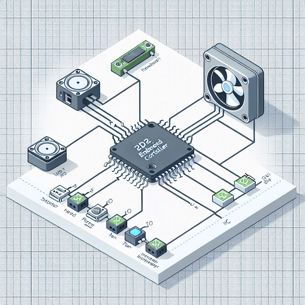
MPTF Drivers
There is 3 primary drivers involved in MPTF
- MPTF Core Driver
- Microsoft Customized IO Driver
- MPTF Customize IO Signal Client
All these drivers are included in OS drops after 26394 as part of the default OS build.
MPTF Core Driver
The Core Driver provides the core logic for MPTF, reads the configuration blob and operates on input and output devices. This driver will not be loaded unless you add the following ACPI entry to load the driver automatically at boot time.
// MPTFCore Driver
Device(MPC0) {
Name(_HID, "MSFT000D")
Name (_UID, 1)
}
You can find this driver under windows driverstore folder
C:\Windows\System32\DriverStore\FileRepository\mptfcore.inf_*
If it is enumerated properly you will see it show up as MPTF Core Driver in device manager.
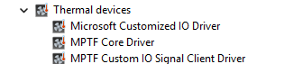
MPTF Core Driver logging can be enable in windbg with the following commands.
!wmitrace.start MptfCore -kd
!wmitrace.enable MptfCore {9BBAB94F-A0B0-4F96-8966-A04F9BA72CA0} -level 0x7 -flag 0xFFFF
Microsoft Customized IO Driver
The Microsoft Customized IO Driver provides a standard interface to the embedded controller to provide input and output values to control fan and thermal properties on the embedded controller.
The ACPI entry for loading the Microsoft Customized IO Driver is as follows
Device(CIO1) {
Name(_HID, "MSFT000B")
Name (_UID, 1)
...
}
For further details on ACPI definitions and customizations for defining IO inputs and outputs see the section on ACPI.
You can find this driver under windows driverstore folder
C:\Windows\System32\DriverStore\FileRepository\mscustomizedio.inf_*
You will find the driver under device manager in Thermal devices as Microsoft Customized IO Driver
Microsoft Customized IO Driver logging can be enabled in windbg with the following commands.
!wmitrace.start MptfIo -kd
!wmitrace.enable MptfIo {D0ABE2A4-A604-4BEE-8987-55C529C06185} -level 0x7 -flag 0xFFFF
MPTF Custom IO Signal Client Driver
The Custom IO Signal Cient Driver provides ability for OEM’s to provide their own custom input and output signals into MPTF. Examples of custom drivers along with input and output definitions can be found in the MPTF specification and are not covered here.
The following ACPI entry will cause the Custom IO Signal Driver to be loaded at boot time.
// MPTF Signal IO Client driver
Device(MPSI) {
Name(_HID, "MSFT0011")
Name (_UID, 1)
}
You can find this driver under windows driverstore folder
C:\Windows\System32\DriverStore\FileRepository\mptfcustomizeiosignalclient.inf_*
If it loads with no errors you will see it loaded as MPTF Custom IO Signal Client Driver in device manager.
Microsoft Temperature Sensor Driver
The Temperature Sensor Driver is an input to MPTF that allows MPTF to take actions based on skin temperature or other sensors external to the CPU. Details of the MPTF temperature sensor can be found in the MTPF specification.
The following ACPI entry is necessary to load the Temperature Sensor Driver
// Skin temperature sensor
Device(TMP1) {
Name(_HID, "MSFT000A")
Name (_UID, 1)
...
The driver is in windows driverstore folder
C:\Windows\System32\DriverStore\FileRepository\mstemperaturesensor.inf_*
If it loads with no failures you should see it listed in device manager
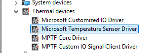
ACPI Entries for MPTF
Windows will boot and run without the MPTF driver loading, however it will not provide any inbox default handling of thermal control.
For any MPTF functionality the Core Driver must be loaded with the following ACPI entry
// MPTFCore Driver
Device(MPC0) {
Name(_HID, "MSFT000D")
Name (_UID, 1)
}
There is no requirement to define further resources through the core driver those are all controlled by the IO driver entries.
Microsoft Temperature Sensor Driver
This driver is loaded uner MSFT000A entry, it must always define a _TMP method and _DSM with support for function 0 and function1. If just these two functions are supported function 0 will return 0x3
Method (_TMP) {
// Check to make sure FFA is available and not unloaded
If(LEqual(\_SB.FFA0.AVAL,One)) {
Name(BUFF, Buffer(24){}) // Create buffer for send/recv data
CreateByteField(BUFF,0,STAT) // Out – Status for req/rsp
CreateByteField(BUFF,1,LENG) // In/Out – Bytes in req, updates bytes returned
CreateField(BUFF,16,128,UUID) // UUID of service
CreateByteField(BUFF,18, CMDD) // In – First byte of command
CreateByteField(BUFF,19, TMP1) // In – Thermal Zone Identifier
CreateField(BUFF,144,32,TMPD) // Out – temperature for TZ
Store(20, LENG)
Store(0x1, CMDD) // EC_THM_GET_TMP
Store(1,TMP1)
Store(ToUUID("31f56da7-593c-4d72-a4b3-8fc7171ac073"), UUID) // Thermal
Store(Store(BUFF, \_SB_.FFA0.FFAC), BUFF)
If(LEqual(STAT,0x0) ) // Check FF-A successful?
{
Return (TMPD)
}
}
Return(Zero)
}
// Update Thresholds
Method(STMP, 0x2, Serialized) {
// Check to make sure FFA is available and not unloaded
If(LEqual(\_SB.FFA0.AVAL,One)) {
Name(BUFF, Buffer(32){}) // Create buffer for send/recv data
CreateByteField(BUFF,0,STAT) // Out – Status for req/rsp
CreateByteField(BUFF,1,LENG) // In/Out – Bytes in req, updates bytes returned
CreateField(BUFF,16,128,UUID) // UUID of service
CreateByteField(BUFF,18, CMDD) // In – First byte of command
CreateByteField(BUFF,19, TID1) // In – Thermal Zone Identifier
CreateDwordField(BUFF,20,THS1) // In – Timeout in ms
CreateDwordField(BUFF,24,THS2) // In – Low threshold tenth Kelvin
CreateDwordField(BUFF,28,THS3) // In – High threshold tenth Kelvin
CreateField(BUFF,144,32,THSD) // Out – Status from EC
Store(0x30, LENG)
Store(0x2, CMDD) // EC_THM_SET_THRS
Store(1,TID1)
Store(0,THS1) // Timout in ms 0 ignore
Store(Arg0,THS2) // Low Threshold
Store(Arg1,THS3) // High Threshold
Store(ToUUID("31f56da7-593c-4d72-a4b3-8fc7171ac073"), UUID) // Thermal
Store(Store(BUFF, \_SB_.FFA0.FFAC), BUFF)
If(LEqual(STAT,0x0) ) // Check FF-A successful?
{
Return (THSD)
}
}
Return(Zero)
}
// Arg0 GUID
// 1f0849fc-a845-4fcf-865c-4101bf8e8d79 - Temperature GUID
// Arg1 Revision
// Arg2 Function Index
// Arg3 Function dependent
Method(_DSM, 0x4, Serialized) {
// Input Variable
If(LEqual(ToUuid("1f0849fc-a845-4fcf-865c-4101bf8e8d79"),Arg0)) {
Switch(Arg2) {
Case(0) {
// We support function 0,1
Return (Buffer() {0x03, 0x00, 0x00, 0x00})
}
// Update Thresholds
// Arg3 = Package () { LowTemp, HighTemp }
Case(1) {
Return(STMP(DeRefOf(Index(Arg3,0)),DeRefOf(Index(Arg3,1)))) // Set Temp low and high threshold
}
}
}
Return (Ones)
}
Microsoft Customized IO Signal Driver
This driver is loaded under MSFT0011 entry, and must always define Function 0 for both input and output devices. Function 0 is a bitmask of all the other variables that are supported on this platform. If you support functions 1,2,3 you would return 0b1111 (0xf) to indicate support for function 0-3.
// Arg0 GUID
// 07ff6382-e29a-47c9-ac87-e79dad71dd82 - Input
// d9b9b7f3-2a3e-4064-8841-cb13d317669e - Output
// Arg1 Revision
// Arg2 Function Index
// Arg3 Function dependent
Method(_DSM, 0x4, Serialized) {
// Input Variable
If(LEqual(ToUuid("07ff6382-e29a-47c9-ac87-e79dad71dd82"),Arg0)) {
Switch(Arg2) {
Case(0) {
// We support function 0-3
Return (Buffer() {0x0f, 0x00, 0x00, 0x00})
}
Case(1) {
Return(GVAR(1,ToUuid("db261c77-934b-45e2-9742-256c62badb7a"))) // MinRPM
}
Case(2) {
Return(GVAR(1,ToUuid("5cf839df-8be7-42b9-9ac5-3403ca2c8a6a"))) // MaxRPM
}
Case(3) {
Return(GVAR(1,ToUuid("adf95492-0776-4ffc-84f3-b6c8b5269683"))) // CurrentRPM
}
}
Return(Ones)
}
// Output Variable
If(LEqual(ToUuid("d9b9b7f3-2a3e-4064-8841-cb13d317669e"),Arg0)) {
Switch(Arg2) {
Case(0) {
// We support function 0-3
Return (Buffer() {0x0f, 0x00, 0x00, 0x00})
}
Case(1) {
Return(SVAR(1,ToUuid("db261c77-934b-45e2-9742-256c62badb7a"),Arg3)) // MinRPM
}
Case(2) {
Return(SVAR(1,ToUuid("5cf839df-8be7-42b9-9ac5-3403ca2c8a6a"),Arg3)) // MaxRPM
}
Case(3) {
Return(SVAR(1,ToUuid("adf95492-0776-4ffc-84f3-b6c8b5269683"),Arg3)) // CurrentRPM
}
}
Return(Ones)
}
Return (Ones)
}
In this case we’ve assigned the following meanings to supported functions
Function 1 --> MinRPM
Function 2 --> MaxRPM
Function 3 --> CurrentRPM
The meaning of what Function 1 does is mapped by the configuration Blob for your device, so Function 1 need not always be MinRPM. For communication with the EC we’ve assigned UUID’s to each variable we support on the EC. This allows us to keep the same UUID for MinRPM on all platform implementations even though it may be a different function.
The following is the list of UUID’s and variables we have defined for our reference implementation, but further mappings can be added by OEM’s as well.
| Variable | GUID | Description | OnTemp | ba17b567-c368-48d5-bc6f-a312a41583c1 | Lowest temperature at which the fan is turned on. | RampTemp | 3a62688c-d95b-4d2d-bacc-90d7a5816bcd | Temperature at which the fan starts ramping from min speed. | MaxTemp | dcb758b1-f0fd-4ec7-b2c0-ef1e2a547b76 | Temperature at top of fan ramp where fan is at maximum speed. | CrtTemp | 218246e7-baf6-45f1-aa13-07e4845256b8 | Critical temperature at which we need to shut down the system. | ProcHotTemp | 22dc52d2-fd0b-47ab-95b8-26552f9831a5 | Temperature at which the EC will assert the PROCHOT notification. | MinRpm | db261c77-934b-45e2-9742-256c62badb7a | Minimum RPM FAN speed | MinDba (Optional) | 0457a722-58f4-41ca-b053-c7088fcfb89d | Minimum Dba from FAN |
MinSones (Optional) | 311668e2-09aa-416e-a7ce-7b978e7f88be | Minimum Sones from FAN | MaxRpm | 5cf839df-8be7-42b9-9ac5-3403ca2c8a6a | Maximum RPM for FAN | MaxDba (Optional) | 372ae76b-eb64-466d-ae6b-1228397cf374 | Maximum DBA for FAN | MaxSones (Optional) | 6deb7eb1-839a-4482-8757-502ac31b20b7 | Maximum Sones for FAN | ProfileType | 23b4a025-cdfd-4af9-a411-37a24c574615 | Set profile for EC, gaming, quiet, lap, etc | CurrentRpm | adf95492-0776-4ffc-84f3-b6c8b5269683 | The current RPM of FAN | CurrentDba (Optional) | 4bb2ccd9-c7d7-4629-9fd6-1bc46300ee77 | The current Dba from FAN | CurrentSones (Optional) | 7719d686-02af-48a5-8283-20ba6ca2e940 | The current Sones from FAN |
|---|
Configuration Blob
The configuration blob data is owned by the OEM and allows custom actions to be taken on output paramters based on input channels and settings.
There are two files used to define configuration of the blob:
- PocSpec.txt - Defines Input and Output GUID’s and actions to map input to outputs
- PocIF.txt - For a given GUID maps valid ranges and mapping to ACPI output functions
Both these files live directly under the root folder, but will likely move in the future.
Note: If these files are not present or found the MPTF Core driver will yellow bang.
PocSpec.txt
This file defines UUID’s for input and output devices. If using an input or output from the OS you must use the existing UUID definitions found in the MPTF documentation.
In this case the output device is defined in the PocIF.txt but must be unique UUID if you are creating your own output channels.
//
// INPUT
#macro I_OS_PWR_MODE_MPTF {8945AB0A-35DD-4BEE-82A5-8138892C280D}_1
//
// OUTPUT
#macro O_FAN1_ACTIVE_RPM {91F589E0-45F0-4C6E-A17D-24FD8E8CBDCE}_730
//
// DEMO-B - OS Power Mode Driven Fan RPM
// Will monitor the OS PWR MODE and then in a lookup TABLE output a target RPM stored in O_FAN1_ACTIVE_RPM
1,0,0,%A_TABLE%,1,1,1,%I_OS_PWR_MODE_MPTF%,%O_FAN1_ACTIVE_RPM%,4,0,0,1,3,5,7,2,4,6,7,15,25,35,45
The last line monitors the input values selected in the OS from the power mode and maps this to output values for O_FAN1_ACTIVE_RPM. The last 4 values are the output values in this case in percentage for the fan speed 15,25,35,45.
@Douglas to fill in further details on the meaning of these other mapping bits
PocIF.txt
This file maps an output channel to an ACPI function along with default, min and max values
// O_FAN1_ACTIVE_RPM
{91F589E0-45F0-4C6E-A17D-24FD8E8CBDCE}_730,1,60,10,20,2,"\_SB.CIO1"
Here the last two parameters maps this output to function 2 in the _DSM function of _SB.CIO1 device in ACPI.
The value before (20) is the default value set if no value is set by the OS.
Previous two values 60,10 are the maximum and minimum valid values.
@Douglas to provide further details on the spec
Debugging
This section describes the order you should follow when validating the MPTF and log files to capture.
Loading Drivers
The first step is to make sure the MPTF drivers are loaded successfully in device manager.
In device manager expand the Thermal devices tab to make sure see the following three devices listed without any yellow bang.
If you don’t see the “Thermal devices” in device manager, you are either missing the ACPI entries or the files are not present in your windows folder. Review the sections on ACPI and the MPTF drivers to make sure all the files are present.
If MPTF Core Driver is present but yellow banged, this is normally because of a failure in parsing the PocIF.txt and PocSpec.txt files in the root folder. Make sure these are present and look valid or try a simpler file. If they are valid collect logs that are listed in the Logging section below and review/share.
If Microsoft Customized IO Driver is present but yellow banged, this is normally an issue with your configuration files and ACPI _DSM definitions for input and output devices. Review your ACPI entries for MSFT0011 and make sure all functions referenced in the PocIF.txt are present and valid in your ACPI tables. For further debug collect logs and see section on ACPI debugging to debug ACPI
If MPTF Custom IO Signal Client River is present but yellow banged, this indicates there is normally a problem in your custom input/output driver component. Enable logging in your driver and make sure it is loaded successfully and no failures. Enable all other logs under logging and review content.
Sometimes drivers will not load correctly if the MPTF service is not running so be sure to make sure in your service manager that MPTF service is running and set to automatically start.
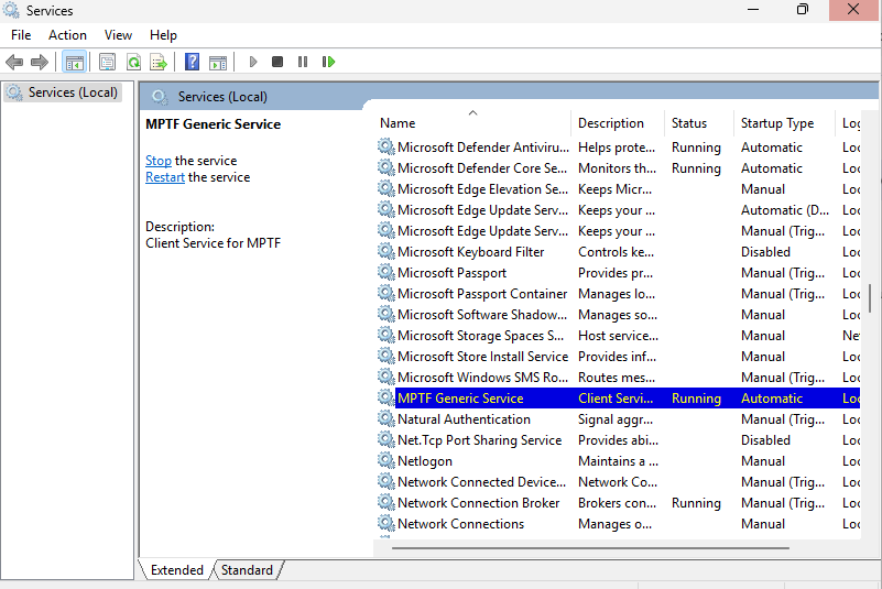
Logging
Logging has moved to EventViewer traces. To view the MPTF events open Event Viewer (eventvwr.msc) and browse to Applications and Services -> Microsoft -> Windows -> MPTF
You will see the MPTF events here for debugging and tracing behaviors.
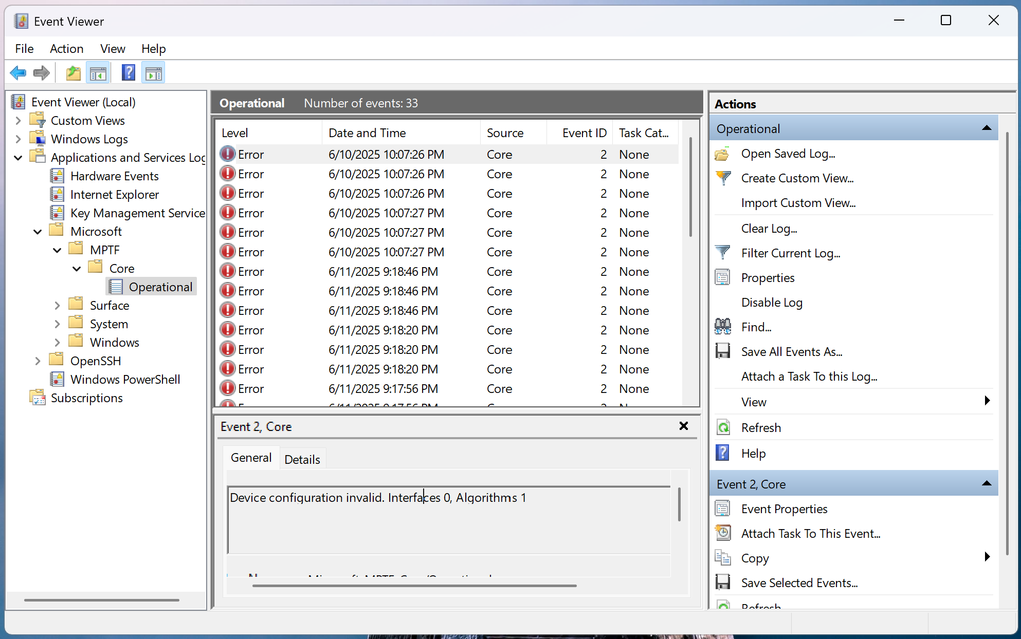
If using secure EC services and sending commands via FFA these logs are captured to the serial port, in this case you should see the output channel value being written to the variable on the serial port logs
15:29:00.621 : SP 8003: DEBUG - set_variable instance id: 0x1
15:29:00.622 : SP 8003: length: 0x4
15:29:00.623 : SP 8003: uuid: 5cf839df-8be7-42b9-9ac5-3403ca2c8a6a
15:29:00.623 : SP 8003: data: 0x19
ACPI Debugging
Since input and output devices go through ACPI calls you may find yourself needing to debug content in ACPI.
!amli set spewon verboseon traceon dbgbrkon
!amli bp \_SB.CIO1._DSM
!amli bl
!amli dns /s \_SB.CIO1
For further details on ACPI debugging see AMLI Debugging
MPTF Tuning
PID Controller
MPTF uses PID controller as computation math function to calculate the appropriate out for various thermal scenario. A PID controller is effective for thermal control because it reacts quickly to inputs, corrects long‑term drift, and reduces overshoot for stable operation. By combining proportional, integral, and derivative actions, it helps a system reach and maintain a stable target output accurately.
- Kp – Proportional Gain
- Ki – Integral Gain
- Kd – Derivative Gain
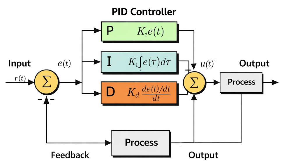
Proportional Term
- Takes the 𝑒(𝑡) value and applies the proportional value.
- A high proportional value would result in a more larger change and a lower proportional value would result in a smaller change.
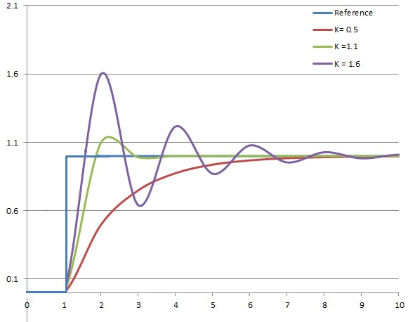
Integral Term
- Takes the integral of 𝑒(𝑡) across an interval, and scales it by the integral gain “Ki”
- Removes the steady state error that’s generated by the proportional term
- Adds overshoot as the integral responds to more accumulated error from integral calculation
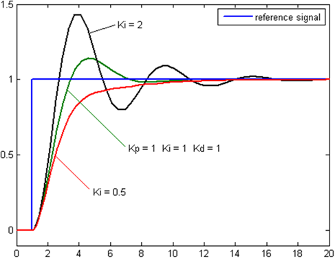
Derivative Term
- Takes the derivative of 𝑒(𝑡) and scales it by the derivative gain “Kd”
- Removes overshoot, and settling time introduced by proportional and integral terms
- If Kd is too large, could introduce stability issues as it anticipates future response
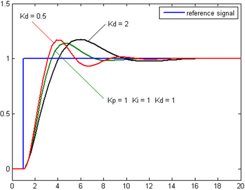
Manual Tuning Example
This is an example of manually tuning a “skin temperature” scenario where the PID controller is configured to ensure the temperature remains within a targeted range that is safe to be touched. Temperature is control by setting the appropriate power level consumption of the SOC (O_SOC_PL1). Data collected was collected on a lab device and is intended to simulate a real scenario. The MPTF configuration is intended to be used as a reference and not for production.
Setup
The Device Under Test is a device that has laptop chassis and is setup with a temperature sensor that is close to the CPU. This ensure the “skin temperature” close to the CPU is always in a safe range. During tuning a benchmark tool is use to trigger a temperature rise by loading the temperature to 100% utilization. Once the temperature value reaches the triggered value of 3170 (Target Temperature - Offset) the PID controller would take effect.
Tuning
The following PID controller configuration is used as starting point to maintain a temperature of 3180dK (44.85 °C). The current configuration value used is too high, causing constant overshoot that we are not able to lock into the desired temperature as the correction to the power levels is always either too high or low. This causes constant fluctuation in both temperature and power consumption. As the graph shows the PID controller remains active constantly trying to adjust the power level and the DUT never settles to a stable temperature.
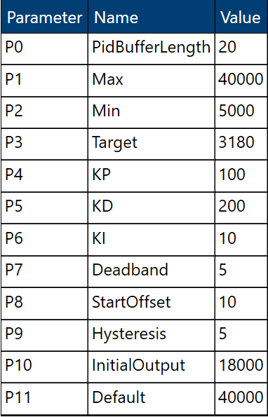
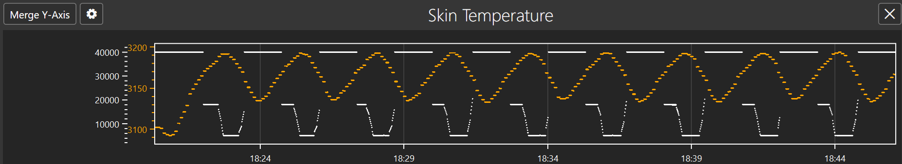
The first step to fix this is to reduce the overshoot. The initial graph also that temperature does not react immediately after power consumption has been increased or reduced. So to take into account the delayed reaction time reduction for both the Proportional (Kp) and Integral (Ki) gains is required. The value of hysteresis is also increased to allow PID controller to remain active as temperature is being adjusted. This avoids falling back to the default maximum power level prematurely when temperature starts dropping. The following configuration shows the updated value.
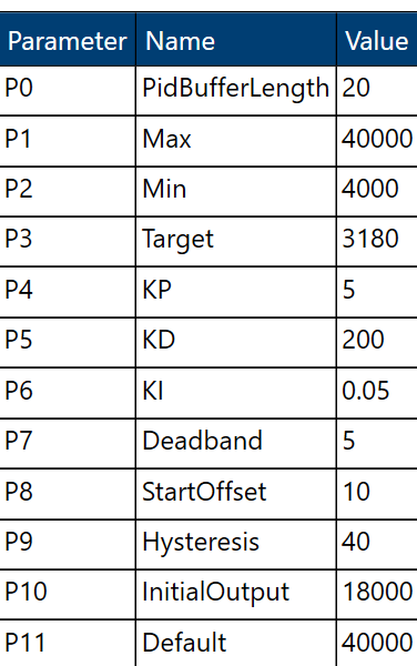
After a while the PID controller is now able to stabilize to the desired temperature target of 180dK (44.85 °C) and has remained stable as the CPU is still being utilized at 100%. At this stage power level is configured to around 26-27mW.
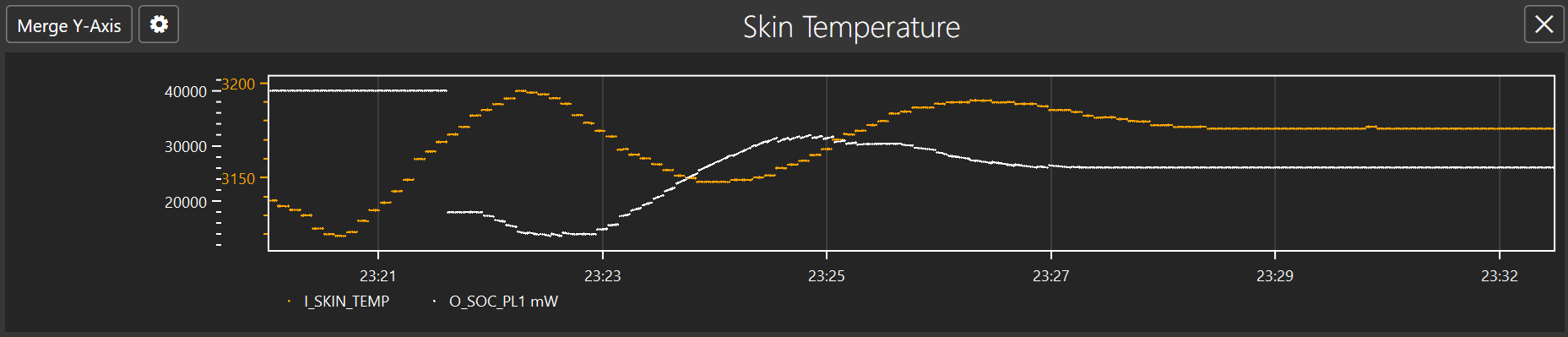
Now that we have found a working PID configuration, it is possible to perform further optimization. The PID configuration had a value of 18mW as an initial output which is the value applied when temperature hits the initial threshold. This value can be adjusted to higher value as the second graph shows temperature reduction on higher power level. Adjusting to higher initial power level improves user experience as a more performant CPU is available. The following graph shows when initial output is set to 22mW where it has similar result as above.
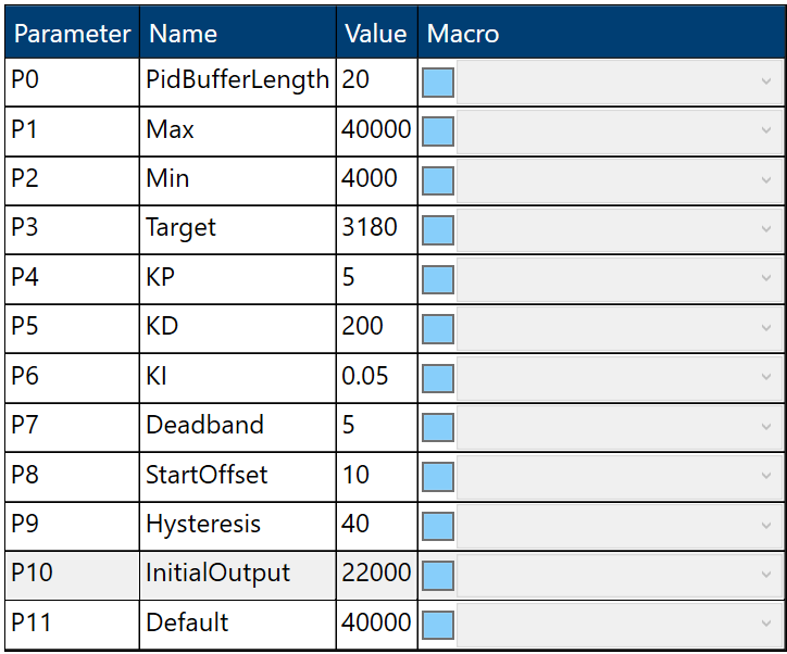
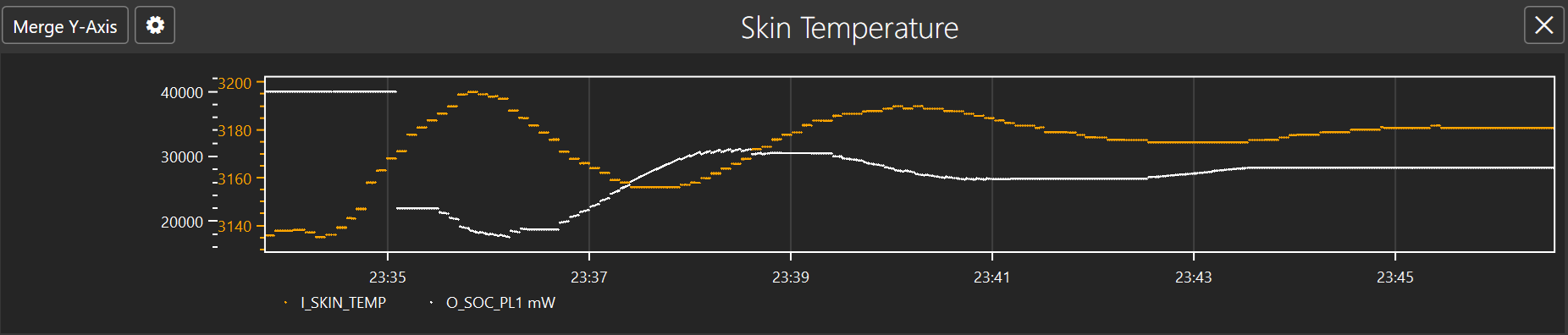
A thermal engineer could perform more fine tuning to eliminate the overshoot completely. The following configuration is used that has reduce the both the Proportional (Kp) and Integral (Ki) gains further to allow a marginal adjustment and avoids the overshoot completely.
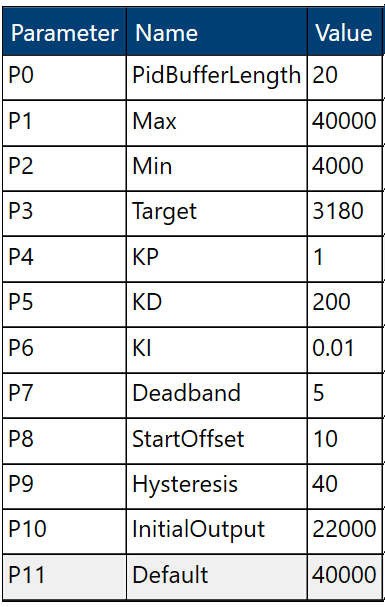
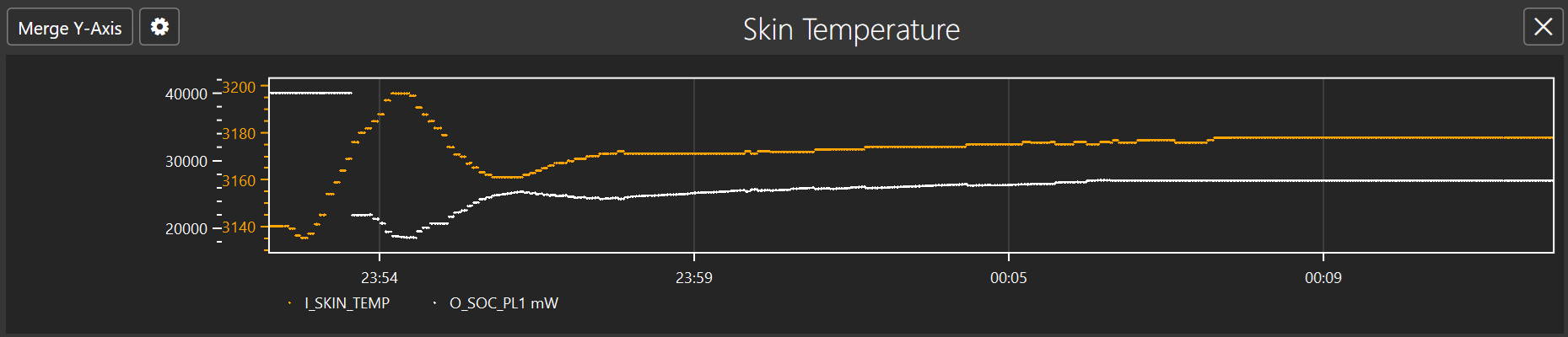
EC Service
On ARM platforms where the interface to the EC is in the secure world, we have a service that runs in the secure world that translates requests from the OS to commands sent to the EC. In the case of MPTF there is a Thermal Service that runs within the EC service to handle requests for custom IO.
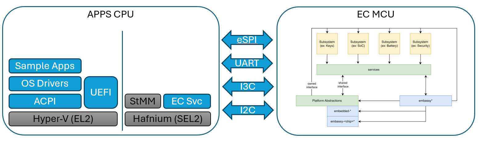
ACPI to EC Service Communication
The EC Specification defines commands for get variable and set variable.
EC_THM_GET_VAR = 0x5
EC_THN_SET_VAR = 0x6
Get variable passes in the following structure.
struct GetVar {
inst: u8, // Instance of thermal device, there may be multiple fans
len: u16, // Length of the variable in this case always 4 bytes
uuid: uuid, // UUID of the variable see spec
}
This will return status and data
Set variable passes in the following structure
struct SetVar {
inst: u8, // Instance of thermal device, there may be multiple fans
len: u16, // Length of the variable in this case always 4 bytes
uuid: uuid, // UUID of the variable see spec
data: u32, // 32-bit data to write to variable
}
Returns status.
See ACPI section for further details of FFA definition and sending commands. The instance is normally hard coded in ACPI based off the instance definition of ACPI.
EC Service to EC Communication
The communication between the EC service in the secure world and over to the EC MCU itself can vary from platform to platform.
In the example given here the EC is connected via eSPI and we map a chunk of memory in the peripheral channel directly to various variables. The variable maps to an offset in the peripheral channel where the read and write is done for the corresponding entry.
The EC Firmware is notified when a region of memory is updated and will adjust fan and hardware logic based on these new values.
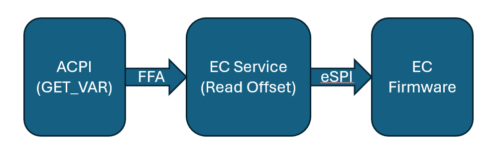
The EC service receives the get/set variable requests in the thermal service
haf-ec-service/ec-service-lib/src/services/thermal/mod.rs
EC_THM_GET_VAR => {
rsp.struct_to_args64(&self.get_variable(msg));
Ok(rsp)
}
EC_THM_SET_VAR => {
rsp.struct_to_args64(&self.set_variable(msg));
Ok(rsp)
}
From here it converts it to eSPI peripheral reads and writes.
EC Service ACPI
Sometimes the GVAR and SVAR from CIO may directly map to memory mapped OpRegion in an EC controller such as on Intel platforms. In the case where EC service is present in the secure world on ARM platforms we need to setup a bit more content.
All the communication between non-secure side (NTOS) and secure side (EC Secure Partition) is done through a standard called FF-A.
FFA ACPI Defintion
Make sure in your system in ACPI you have FFA device defined and corresponding _DSD and _DSM methods according to FFA documentation.
Device(\_SB_.FFA0) {
Name(_HID, "MSFT000C")
OperationRegion(AFFH, FFixedHw, 2, 144)
Field(AFFH, BufferAcc, NoLock, Preserve) { AccessAs(BufferAcc, 0x1), FFAC, 1152 }
...
Method(AVAL,0x0, Serialized)
{
Return(One)
}
This should also implment the AVAL function to determine that FFA is loaded and can be used by other ACPI references. If you directly reference FFA0 without checking this if the FFA driver is not loaded can lead to deadlock and other OS issues.
Making FFA Calls
As previously documented in the MPTF section, in the SVAR and GVAR we make calls into FFA. This section documents those parameters in more detail.
If(LEqual(\_SB.FFA0.AVAL,One)) { // First check to make sure FFA0 device is available
Name(BUFF, Buffer(52){}) // Allocate a buffer large enough for all input and output data
CreateField(BUFF, 0, 64, STAT) // All FFA commands must have 64-bits status returned
CreateField(BUFF, 64, 64, RCVD) // ReceiverId left as zero is populated by the framework
CreateField(BUFF, 128, 128, UUID) // UUID of service we want to talk to in this case Thermal Service
CreateField(BUFF, 256, 8, CMDD) // Command to send to this service
CreateField(BUFF, 264, 8, INST) // Remaining entries are command specific input and output structure definition
CreateField(BUFF, 272, 16, VLEN)
CreateField(BUFF, 288, 128, VUID)
CreateField(BUFF, 264, 64, RVAL) // Output structure will overlap with input data
Store(ToUUID("31f56da7-593c-4d72-a4b3-8fc7171ac073"), UUID) // Populate the Thermal Service UUID
Store(0x5, CMDD) // Write command EC_THM_GET_VAR into buffer
Store(Arg0,INST) // Save instance ID into buffer
Store(4,VLEN) // Variable is always DWORD here
Store(Arg1, VUID) // Variable UUID
Store(Store(BUFF, \_SB_.FFA0.FFAC), BUFF) // Writes BUFF to FFA operation region this actually sends FFA request and gets response
If(LEqual(STAT,0x0) ) // Check FF-A successful?
{
Return (RVAL) // Return data in the out buffer
}
}
// Otherwise return an error
For MPTF we mostly just need Get/Set varaible commands and notifications.
EC Notifications
The EC can also send notifications back to the OS if certain events occur. All the notifications come initially through the FFA0 device. When device is defined in ACPI you must list all the logical notification events you expect and the handler for notifications.
Name(_DSD, Package() {
ToUUID("daffd814-6eba-4d8c-8a91-bc9bbf4aa301"), //Device Prop UUID
Package() {
Package(2) {
"arm-arml0002-ffa-ntf-bind",
Package() {
1, // Revision
1, // Count of following packages
Package () {
ToUUID("31f56da7-593c-4d72-a4b3-8fc7171ac073"), // UUID for thermal
Package () {
0x01, // EC_THM_HOT
0x02, // EC_THM_LOW crossed low threshold
0x03, // EC_THM_HIGH crossed high threshold
}
}
}
}
}
}) // _DSD()
Method(_DSM, 0x4, NotSerialized)
{
// Arg0 - UUID
// Arg1 - Revision
// Arg2: Function Index
// 0 - Query
// 1 - Notify
// 2 - binding failure
// 3 - infra failure
// Arg3 - Data
//
// Device specific method used to query
// configuration data. See ACPI 5.0 specification
// for further details.
//
If(LEqual(Arg0, Buffer(0x10) {
//
// UUID: {7681541E-8827-4239-8D9D-36BE7FE12542}
//
0x1e, 0x54, 0x81, 0x76, 0x27, 0x88, 0x39, 0x42, 0x8d, 0x9d, 0x36, 0xbe, 0x7f, 0xe1, 0x25, 0x42
}))
{
// Query Function
If(LEqual(Arg2, Zero))
{
Return(Buffer(One) { 0x03 }) // Bitmask Query + Notify
}
// Notify Function
If(LEqual(Arg2, One))
{
// Arg3 - Package {UUID, Cookie}
Local0 = DeRefOf(Index(Arg3,1))
Store(Local0,\_SB.ECT0.NEVT )
Switch(Local0) {
Case(1) {
// Handle HOT notification
}
Case(2) {
// Handle Low temp notification
}
Case(3) {
// Handle High temp notification
}
}
}
} Else {
Return(Buffer(One) { 0x00 })
}
}
EC Service Debugging
Since the EC service runs in the secure world you cannot debug it through windbg. Most debugging is done through serial log messages or JTAG with SWD.
For SWD debugging see references to Hafnium and JTAG debugging.
Serial Debug
In the code you can simply use println or logging interface and these messages will be routed to serial port by default.
Eg.
println!(
"set_variable instance id: 0x{:x}
length: 0x{:x}
uuid: {}
data: 0x{:x}",
req.id, req.len, req.var_uuid, req.data
);
You will see these messages printed out on the serial terminal
15:29:00.621 : SP 8003: DEBUG - set_variable instance id: 0x1
15:29:00.622 : SP 8003: length: 0x4
15:29:00.623 : SP 8003: uuid: 5cf839df-8be7-42b9-9ac5-3403ca2c8a6a
15:29:00.623 : SP 8003: data: 0x19
MCU Firmware
The MCU Firmware has a region of 256 bytes that is mapped as the peripheral channel on eSPI. This is used to read and write 32-bit values to and from the EC. Based on the parameters that we read and write the MCU firmware will adjust fan speeds and other parameters within the EC that adjust thermal.
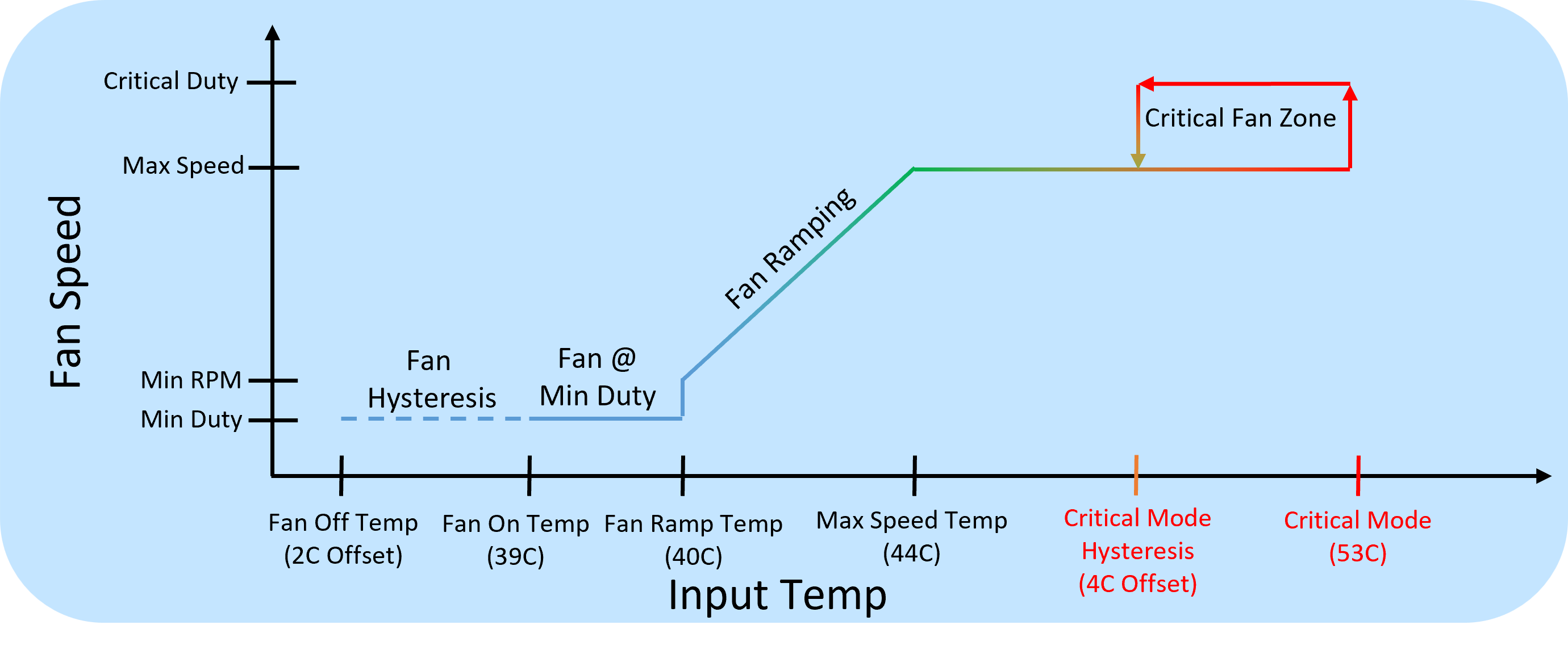
Apps to MCU Interface
When using eSPI transport we define a mapped memory region in the peripheral bus, that must be agreed on between apps side and MCU side.
Memory Layout Definition
Both apps side and MCU side are using RUST, we define the memory layout in YAML format and currently have a python script that converts this to a RUST format.
embedded-services/embedded-service/src/ec_type/generator/ec_memory.yaml
# EC Memory layout definition
Version:
major:
type: u8
minor:
type: u8
spin:
type: u8
res0:
type: u8
...
# Size 0x38
Thermal:
events:
type: u32
cool_mode:
type: u32
dba_limit:
type: u32
sonne_limit:
type: u32
ma_limit:
type: u32
fan1_on_temp:
type: u32
fan1_ramp_temp:
type: u32
fan1_max_temp:
type: u32
fan1_crt_temp:
type: u32
fan1_hot_temp:
type: u32
fan1_max_rpm:
type: u32
fan1_cur_rpm:
type: u32
tmp1_val:
type: u32
tmp1_timeout:
type: u32
tmp1_low:
type: u32
tmp1_high:
type: u32
Converting YAML to RUST
To convert YAML to RUST simply run the ec-memory-generator.py using the following command
python ec-memory-generator.py ec_memory.yaml
This will outut the following two files for C based structure definition and RUST based
structure.rs
ecmemory.h
When compiling embedded-services the structure.rs must be copied under
embedded-services/embedded-service/src/ec_type
Versioning
Any time a breaking change is made the major version must be updated and if EC and apps don’t agree on a major version the fields cannot be interpreted. Whenever possible we only want to add fields which means we can keep the structure backwards compatible and just the minor version can be updated.
MCU eSPI Service
When the apps modifies or writes some value into the peripheral channel on the MCU side a service can register for notifications to specific regions of the memory map. The handling of all eSPI events can be found in
embedded-services/espi-service/src/espi_service.rs
This contains the entry point and main message handling loop.
#[embassy_executor::task]
pub async fn espi_service(mut espi: espi::Espi<'static>, memory_map_buffer: &'static mut [u8]) {
info!("Reserved eSPI memory map buffer size: {}", memory_map_buffer.len());
info!("eSPI MemoryMap size: {}", size_of::<ec_type::structure::ECMemory>());
...
loop {
...
}
VWire events and Peripheral channel events come in on Port 0, while OOB messages come in on Port 1. For details about the eSPI protocol see the eSPI secification
Based on the offset of the access in the peripheral channel the data is routed to the correct service
if offset >= offset_of!(ec_type::structure::ECMemory, therm)
&& offset < offset_of!(ec_type::structure::ECMemory, therm) + size_of::<ec_type::structure::Thermal>()
{
self.route_to_thermal_service(&mut offset, &mut length).await?;
}
This gets converted to a transport independent message and routed to the thermal endpoint that can register and listen for these messages
async fn route_to_thermal_service(&self, offset: &mut usize, length: &mut usize) -> Result<(), ec_type::Error> {
let msg = {
let memory_map = self.ec_memory.borrow();
ec_type::mem_map_to_thermal_msg(&memory_map, offset, length)?
};
comms::send(
EndpointID::External(External::Host),
EndpointID::Internal(Internal::Thermal),
&msg,
)
.await
.unwrap();
Ok(())
}
```
MCU Debugging
Debugging on the MCU side is done primarily with J-Link SWD connection. Some platforms will provide a dedicated serial port to the MCU that allows debug print messages.
J-Link Debugging
With JTAG debugger you can set breakpoints and step through MCU side code as well as print messages out through the JTAG port using probe-rs.
info!("Reserved eSPI memory map buffer size: {}", memory_map_buffer.len());
info!("eSPI MemoryMap size: {}", size_of::<ec_type::structure::ECMemory>());
@Jerry and Felipe to provide further details or link to MCU debugging document
MPTF Demo
Prerequisites
You will need a hardware platform that has the following:
- Boots OS 26400 or later with MPTF support
- ACPI changes for Custom IO and MPTF driver loading
- haf-ec-service with eSPI or other transport from ODP
- MCU firmware code that runs on your MCU from ODP
MPTF and Customized IO
After booting the device copy both the following PocIF.txt and PocSpec.txt to root folder on the device
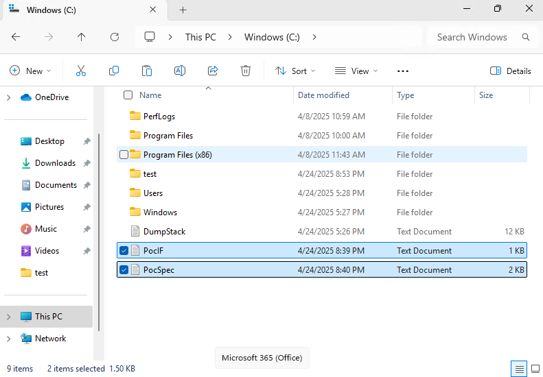
After copying these files we reboot the computer and check in device manager to make sure MPTF devices are all running with no failures.
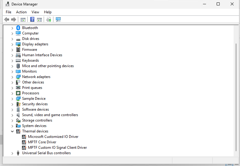
Open System Settings and select Power
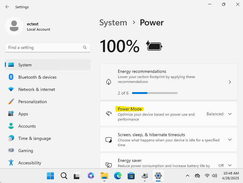
With windbg connecteded and logging enabled for Microsoft Custom IO driver when we change the power mode we will see values being selected.
!wmitrace.stop MptfIo -kd
!wmitrace.start MptfIo -kd
!wmitrace.enable MptfIo {D0ABE2A4-A604-4BEE-8987-55C529C06185} -level 0x7 -flag 0xFFFF
!wmitrace.dynamicprint 1
.reload /f
As you select the different values for Balanced, Best Performance etc you will see it executing the Customized IO functions with the corresponding values defined form the PocSpec.
[1]0004.03A4::04/28/2025-10:58:28.051 [kernel] [SmfInterface_RequestCompletionHandling]Deferred execution: Data write activated
[1]0004.03A4::04/28/2025-10:58:28.067 [mptfcustomizeiosignalclient] [MptfInterfaceDataSet]MptfInterfaceDataSet Received data on channel:0 with value:35 FunctionId 2.
[3]0004.03A4::04/28/2025-10:58:30.211 [kernel] [SmfInterface_RequestCompletionHandling]Deferred execution: Data write activated
[3]0004.03A4::04/28/2025-10:58:30.243 [mptfcustomizeiosignalclient] [MptfInterfaceDataSet]MptfInterfaceDataSet Received data on channel:0 with value:25 FunctionId 2.
[1]0004.03A4::04/28/2025-10:58:32.387 [kernel] [SmfInterface_RequestCompletionHandling]Deferred execution: Data write activated
[1]0004.03A4::04/28/2025-10:58:32.403 [mptfcustomizeiosignalclient] [MptfInterfaceDataSet]MptfInterfaceDataSet Received data on channel:0 with value:15 FunctionId 2.
Hafnium EC Service
Now we demonstrate that the data is received and requests are processed in secure world side. Connecting terminal to our debug serial port we can get the Hanfnium debug messages for each of these power modes we select.
We see that it calls set_variable for instance id: 0x1 with the variable UUID we specify in our ACPI the the value select from the UI
11:02:10.823 : SP 8003: DEBUG - Successfully received ffa msg:
11:02:10.824 : SP 8003: function_id = c400008d
11:02:10.824 : SP 8003: uuid = 31f56da7-593c-4d72-a4b3-8fc7171ac073
11:02:10.824 : SP 8003: DEBUG - Received ThmMgmt command 0x6
11:02:10.824 : SP 8003: DEBUG - set_variable instance id: 0x1
11:02:10.824 : SP 8003: length: 0x4
11:02:10.824 : SP 8003: uuid: 5cf839df-8be7-42b9-9ac5-3403ca2c8a6a
11:02:10.824 : SP 8003: data: 0x23
11:02:12.647 : SP 8003: DEBUG - Successfully received ffa msg:
11:02:12.647 : SP 8003: function_id = c400008d
11:02:12.648 : SP 8003: uuid = 31f56da7-593c-4d72-a4b3-8fc7171ac073
11:02:12.648 : SP 8003: DEBUG - Received ThmMgmt command 0x6
11:02:12.648 : SP 8003: DEBUG - set_variable instance id: 0x1
11:02:12.648 : SP 8003: length: 0x4
11:02:12.648 : SP 8003: uuid: 5cf839df-8be7-42b9-9ac5-3403ca2c8a6a
11:02:12.648 : SP 8003: data: 0x19
11:02:14.199 : SP 8003: DEBUG - Successfully received ffa msg:
11:02:14.199 : SP 8003: function_id = c400008d
11:02:14.200 : SP 8003: uuid = 31f56da7-593c-4d72-a4b3-8fc7171ac073
11:02:14.200 : SP 8003: DEBUG - Received ThmMgmt command 0x6
11:02:14.200 : SP 8003: DEBUG - set_variable instance id: 0x1
11:02:14.200 : SP 8003: length: 0x4
11:02:14.200 : SP 8003: uuid: 5cf839df-8be7-42b9-9ac5-3403ca2c8a6a
11:02:14.200 : SP 8003: data: 0xf
EC MCU Functionality
Finally we validate that the uCode running on the MCU actually receives this data and takes the correct corresponding action. In this example we directly map this variable to the fan RPM as a percentage. As you change the setting in the UI and see the commands in Hafnium EC Service changing values in peripheral channel on the MCU side we receive those notfications and set the fan speed accordingly
Add debug output from MCU here as well.
The Thermal Component Example
In this example we will be constructing a functioning mock thermal component subsystem, similar to what we have done previously for Battery and Charger components.
Goals
The thermal itself will be virtual - no hardware required - and the behavioral aspects of it will be simulated. We will, however, discuss what one would do to implement actual thermal hardware control in a HAL layer.
In this example, we will:
- Define the Traits of the thermal component
- Identify the hardware actions that fulfill these traits
- Define the HAL traits to match these hardware actions
- Implement the HAL traits to hardware access (or define mocks for a virtual example)
- Wrap this simple Traits implementation into a Device for service insertion
- Provide the service layer and insert the device into it
- Test the end result with unit tests and simple executions
How we will build the Thermal Component
We will now start building the component. The first step is to create a new project for the thermal component, which we will call thermal_project. This project will be a workspace that contains the thermal service and the mock thermal component.
Two components: Mock Sensor and Mock Fan
In the previous examples, we created mock battery and charger components. In this example, we will create two components: a mock sensor and a mock fan. These components will be used to simulate the behavior of the thermal component.
Each component is independent, but is orchestrated together by policy. Later, when we do the integration testing, we will explore this choreography in more detail.
For this project, we will focus on the sensor and fan components themselves, and provide unit tests for them.
Thermal component Diagrams
Our Thermal component subsystem will be pretty simple and basic. It will be comprised of one temperature and one fan.
More sensors and more fans or other thermal mitigation hardware solutions could be added to any given real-world implementation using the same patterns.
flowchart LR
%% overall left-to-right so the two lanes sit side-by-side
%% ─────────────────────────────────────────────────────────
subgraph SVC[Service Layer]
svc[Service<br/><i>message / request</i>]
end
subgraph SUBSYS[Thermal Subsystem]
direction LR
%% ── Sensor lane ───────────────────────────────────────
subgraph SENSOR[Sensor path]
SC[Sensor Controller<br/><i>policy, hysteresis</i>]
ST[Thermal Traits<br/><code>TemperatureSensor</code><br/><code>TemperatureThresholdSet</code>]
SM[MockSensor Device<br/><i>device wrapper</i>]
end
%% ── Fan lane ──────────────────────────────────────────
subgraph FAN[Fan path]
FC[Fan Controller<br/><i>policy, spin-up</i>]
FT[Fan Traits<br/><code>Fan</code><br/><code>RpmSense</code>]
FM[MockFan Device<br/><i>device wrapper</i>]
end
end
subgraph HW[Virtual / Hardware State]
HS[VirtualTemperatureState<br/><i>temperature + thresholds</i>]
HF[VirtualFanState<br/><i>rpm</i>]
end
%% wiring
svc --> SC
svc --> FC
SC --> ST --> SM --> HS
FC --> FT --> FM --> HF
When in operation, it conducts its operations in response to message events according to behavior logic that we will define and test here.
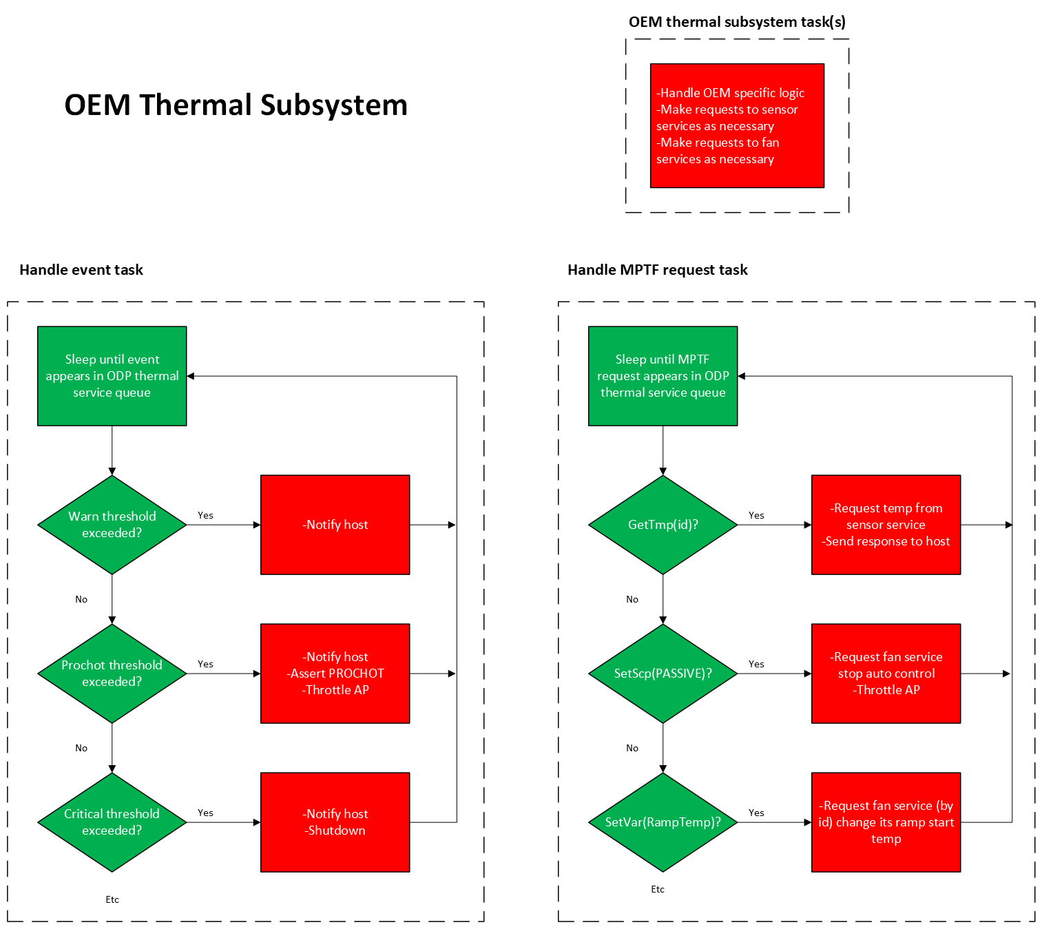
Building the component
We will now start building the component. The first step is to create a new project for the thermal component, which we will call thermal_project. This project will be a workspace that contains the thermal service and the mock thermal component.
we will then follow what by now should be a familiar pattern for creating the mock components, defining the traits, and implementing the HAL traits to access the hardware (or mocks for a virtual example).
Then we’ll wrap this simple Traits implementation into a Device for service insertion, provide the service layer, and insert the device into it. From there we can attach the controller that we can register with the EC service.
At this point we will have a functioning mock thermal component subsystem, similar to what we have done previously for Battery and Charger components, and we will be able to test the end result with unit tests and simple executions.
A Mock Thermal Subsystem Project
We will follow the pattern we established for the battery and charger – in their post-integration-refactored form. That is, we will create a standalone project space for thermal work, but within the shared scope of the common dependencies that we can use later for integration work.
Starting from the shared directory used for the previous integration exercise (ec_examples), we will create the thermal project space:
cd ec_examples
mkdir thermal_project
cd thermal_project
cargo new --lib mock_thermal
Then, create thermal_project/Cargo.toml.
Some of the dependencies we need are already a part of the repositories already in place in our ec_examples containing folder, particularly within embedded-services. The thermal-service is a sub-section of this repository. To reference it directly,though, we will define it as thermal-service in our Cargo.toml.
Use this content for thermal_project/Cargo.toml to start:
# thermal_project/Cargo.toml
[workspace]
resolver = "2"
members = [
"mock_thermal"
]
[workspace.lints]
[workspace.dependencies]
embedded-services = { path = "../embedded-services/embedded-service" }
battery-service = { path = "../embedded-services/battery-service" }
embedded-batteries = { path = "../embedded-batteries/embedded-batteries" }
embedded-batteries-async = { path = "../embedded-batteries/embedded-batteries-async" }
embedded-cfu-protocol = { path = "../embedded-cfu" }
embedded-usb-pd = { path = "../embedded-usb-pd" }
thermal-service = { path = "../embedded-services/thermal-service" }
embedded-sensors-hal-async = { path = "../embedded-sensors/embedded-sensors-async"}
embedded-fans-async = { path = "../embedded-fans/embedded-fans-async"}
embassy-executor = { path = "../embassy/embassy-executor", features = ["arch-std", "executor-thread"], default-features = false }
embassy-time = { path = "../embassy/embassy-time" }
embassy-sync = { path = "../embassy/embassy-sync", features = ["std"] }
embassy-futures = { path = "../embassy/embassy-futures" }
embassy-time-driver = { path = "../embassy/embassy-time-driver" }
embedded-hal = "1.0"
embedded-hal-async = "1.0"
once_cell = "1.19"
static_cell = "2.1.0"
defmt = "1.0"
log = "0.4.27"
bitfield = "0.19.1"
bitflags = "1.0"
bitvec = "1.0"
cfg-if = "1.0"
chrono = "0.4.41"
tokio = { version = "1.45", features = ["full"] }
uuid = "1.0"
critical-section = {version = "1.0", features = ["std"] }
document-features = "0.2.11"
embedded-hal-nb = "1.0"
embedded-io = "0.6.1"
embedded-io-async = "0.6.1"
embedded-storage = "0.3.1"
embedded-storage-async = "0.4.1"
fixed = "1.0"
heapless = "0.8.0"
postcard = "1.0"
rand_core = "0.9.3"
serde = "1.0"
cortex-m = "0.7.7"
cortex-m-rt = "0.7.5"
[patch.crates-io]
embassy-executor = { path = "../embassy/embassy-executor" }
embassy-time = { path = "../embassy/embassy-time" }
embassy-sync = { path = "../embassy/embassy-sync" }
embassy-futures = { path = "../embassy/embassy-futures" }
embassy-time-driver = { path = "../embassy/embassy-time-driver" }
embedded-batteries-async = { path = "../embedded-batteries/embedded-batteries-async" }
}
Update the main workspace cargo at ec_examples\Cargo.toml to look like this:
# ec_examples/Cargo.toml
[workspace]
resolver = "2"
members = [
"battery_project/mock_battery",
"charger_project/mock_charger",
"thermal_project/mock_thermal",
"battery_charger_subsystem",
"ec_common"
]
[workspace.dependencies]
embedded-services = { path = "embedded-services/embedded-service" }
battery-service = { path = "embedded-services/battery-service" }
embedded-batteries = { path = "embedded-batteries/embedded-batteries" }
embedded-batteries-async = { path = "embedded-batteries/embedded-batteries-async" }
embedded-cfu-protocol = { path = "embedded-cfu" }
embedded-usb-pd = { path = "embedded-usb-pd" }
thermal-service = { path = "embedded-services/thermal-service" }
embedded-sensors-hal-async = { path = "embedded-sensors/embedded-sensors-async"}
embedded-fans-async = { path = "embedded-fans/embedded-fans-async"}
embassy-executor = { path = "embassy/embassy-executor", features = ["arch-std", "executor-thread"], default-features = false }
embassy-time = { path = "embassy/embassy-time", features=["std"], default-features = false }
embassy-sync = { path = "embassy/embassy-sync", features = ["std"] }
embassy-futures = { path = "embassy/embassy-futures" }
embassy-time-driver = { path = "embassy/embassy-time-driver", default-features = false}
embassy-time-queue-utils = { path = "embassy/embassy-time-queue-utils" }
embedded-hal = "1.0"
embedded-hal-async = "1.0"
once_cell = "1.19"
static_cell = "2.1.0"
defmt = "1.0"
log = "0.4.27"
bitfield = "0.19.1"
bitflags = "1.0"
bitvec = "1.0"
cfg-if = "1.0"
chrono = "0.4.41"
tokio = { version = "1.45", features = ["full"] }
uuid = "1.0"
critical-section = {version = "1.0", features = ["std"] }
document-features = "0.2.11"
embedded-hal-nb = "1.0"
embedded-io = "0.6.1"
embedded-io-async = "0.6.1"
embedded-storage = "0.3.1"
embedded-storage-async = "0.4.1"
fixed = "1.0"
heapless = "0.8.0"
postcard = "1.0"
rand_core = "0.9.3"
serde = "1.0"
cortex-m = "0.7.7"
cortex-m-rt = "0.7.5"
[patch.crates-io]
embassy-executor = { path = "embassy/embassy-executor" }
embassy-time = { path = "embassy/embassy-time" }
embassy-sync = { path = "embassy/embassy-sync" }
embassy-futures = { path = "embassy/embassy-futures" }
embassy-time-driver = { path = "embassy/embassy-time-driver" }
embassy-time-queue-utils = { path = "embassy/embassy-time-queue-utils" }
embedded-batteries-async = { path = "embedded-batteries/embedded-batteries-async" }
# Lint settings for the entire workspace.
# We start with basic warning visibility, especially for upcoming Rust changes.
# Additional lints are listed here but disabled by default, since enabling them
# may trigger warnings in upstream submodules like `embedded-services`.
#
# To tighten enforcement over time, you can uncomment these as needed.
[workspace.lints.rust]
warnings = "warn" # Show warnings, but do not fail the build
future_incompatible = "warn" # Highlight upcoming breakage (future Rust versions)
# rust_2018_idioms = "warn" # Enforce idiomatic Rust style (may warn on legacy code)
# unused_crate_dependencies = "warn" # Detect unused deps — useful during cleanup
# missing_docs = "warn" # Require documentation for all public items
# unsafe_code = "deny" # Forbid use of `unsafe` entirely
[patch.'https://github.com/embassy-rs/embassy']
embassy-time = { path = "./embassy/embassy-time" }
embassy-time-driver = { path = "./embassy/embassy-time-driver" }
embassy-sync = { path = "./embassy/embassy-sync" }
embassy-executor = { path = "./embassy/embassy-executor" }
embassy-futures = { path = "./embassy/embassy-futures" }
Including embedded-sensors and embedded-fans
We need to add another pair of repository dependencies to our existing set at ec_examples. From the ec_examples folder,
bring in the embedded-sensors and the embedded-fans repository like so:
git clone git@github.com:OpenDevicePartnership/embedded-sensors.git
git clone git@github.com:OpenDevicePartnership/embedded-fans.git
Pre-Testing the project configuration
from the ec_examples/thermal_project folder typing
cargo build
and from the ec_examples folder, typing
cargo build -p mock_thermal
Should both build successfully. This means the Cargo.toml files are in the correct relationship.
(Note: The thermal_project/Cargo.toml workspace configuration is somewhat redundant, but necessary to be consistent with the way the battery and charger projects were originally established.)
Using the ODP repositories for defined Thermal traits
The ODP repositories contain the necessary traits and services for building a thermal subsystem. We will use these traits to define the behavior of our mock thermal component. These traits define the interface for the controller, and therefore inform the implementation of the components.
Thermal component Traits
The Sensor component has traits defined by the embedded-sensors-hal-async crate, which provides the necessary traits for sensor operations. The Fan component has traits defined by the embedded-fans-async crate, which provides the necessary traits for fan operations.
Sensor Traits
TemperatureSensor is the trait that defines the behavior of a temperature sensor. It is a very simple interface that contains only a single method, temperature, which returns the current temperature reading.
TemperatureThresholdSet is a trait that defines the setting of high/low temperature thresholds. Our our implementation will use this, as well as defining some associated events, and will build a default policy around how to orchestrate behavior based on these thresholds and the temperature readings.
Fan Traits
Fan is the trait that defines the behavior of a fan. It contains methods for reading the current fan speed, setting the fan speed, and setting the min, max and starting speed values.
RpmSense is the defined trait for returning the current RPM of the fan.
Pass it on down
The traits methods appear first in the implementation of the controller, which will be reacting to event messages that come from the service layer in an integrated system. In most cases, the functionality is passed through to the underlying layers of the component. All hardware-related state management is handled at the HAL layer (or in our case, virtual layer), the decision logic is handled via the controller so that it can conduct this orchestration.
Implementing the Traits
Let’s start with the Sensor component. We will implement the TemperatureSensor and TemperatureThresholdSet traits in our mock sensor component.
Before we do that, we will need to define the HAL traits that will be used to access the hardware. As with our other mock examples, we are not connecting to any real hardware, so we will define a virtual sensor with the traits we need.
Create a new file in the thermal_project workspace, src/virtual_temperature.rs, and give it this content:
#![allow(unused)]
fn main() {
use embedded_sensors_hal_async::temperature::DegreesCelsius;
#[derive(Copy, Clone, Debug)]
pub struct VirtualTemperatureState {
pub temperature: DegreesCelsius,
pub threshold_low: DegreesCelsius,
pub threshold_high: DegreesCelsius
}
impl VirtualTemperatureState {
pub fn new() -> Self {
Self {
temperature: 0.0,
threshold_low: f32::NEG_INFINITY,
threshold_high: f32::INFINITY
}
}
}
}And then we can use this as the basis for our mock sensor implementation.
Create a new file in the thermal_project workspace, src/mock_sensor.rs, and give it this content:
#![allow(unused)]
fn main() {
use embedded_sensors_hal_async::sensor;
use embedded_sensors_hal_async::temperature::{DegreesCelsius, TemperatureSensor, TemperatureThresholdSet};
use crate::virtual_temperature::VirtualTemperatureState;
#[derive(Copy, Clone, Debug)]
pub struct MockSensor {
temperature_state:VirtualTemperatureState
}
#[derive(Clone, Debug)]
pub struct MockSensorError;
impl sensor::Error for MockSensorError {
fn kind(&self) -> sensor::ErrorKind {
sensor::ErrorKind::Other
}
}
impl sensor::ErrorType for MockSensor {
type Error = MockSensorError;
}
impl MockSensor {
pub fn new() -> Self {
Self {
temperature_state: VirtualTemperatureState::new()
}
}
pub fn get_temperature(&self) -> f32 {
self.temperature_state.temperature
}
pub fn get_threshold_low(&self) -> f32 {
self.temperature_state.threshold_low
}
pub fn get_threshold_high(&self) -> f32 {
self.temperature_state.threshold_high
}
pub fn set_temperature(&mut self, temperature: DegreesCelsius) {
self.temperature_state.temperature = temperature;
}
}
impl TemperatureSensor for MockSensor {
async fn temperature(&mut self) -> Result<DegreesCelsius, Self::Error> {
let d : DegreesCelsius = self.temperature_state.temperature;
Ok(d)
}
}
impl TemperatureThresholdSet for MockSensor {
async fn set_temperature_threshold_low(&mut self, threshold: DegreesCelsius) -> Result<(), Self::Error> {
self.temperature_state.threshold_low = threshold;
Ok(())
}
async fn set_temperature_threshold_high(&mut self, threshold: DegreesCelsius) -> Result<(), Self::Error> {
self.temperature_state.threshold_high = threshold;
Ok(())
}
}
}As you can see, we have implemented the TemperatureSensor and TemperatureThresholdSet traits for our MockSensor component. The actual state values are stored in the VirtualTemperatureState struct, which is used to simulate the behavior of a real temperature sensor. This is where a real sensor would read from hardware, but in our case we are simply simulating the behavior.
Fan Component Implementation
Next, we will implement the Fan component. Just like with the sensor, we will define a virtual fan state and then implement the Fan and RpmSense traits.
Create a new file in the thermal_project workspace, for example src/virtual_fan.rs, and give it this content:
#![allow(unused)]
fn main() {
pub const FAN_RPM_MINIMUM: u16 = 1000; // minimum speed in operation
pub const FAN_RPM_MAXIMUM: u16 = 5000; // maximum speed in operation
pub const FAN_RPM_START: u16 = 1000; // minimum speed at which to start fan
pub struct VirtualFanState {
pub rpm: u16,
pub min_rpm: u16,
pub max_rpm: u16,
pub min_start_rpm: u16
}
impl VirtualFanState {
pub fn new() -> Self {
Self {
rpm: 0,
min_rpm: FAN_RPM_MINIMUM,
max_rpm: FAN_RPM_MAXIMUM,
min_start_rpm: FAN_RPM_START
}
}
}
}And then we can use this as the basis for our mock fan implementation.
Create a new file src/mock_fan.rs, and give it this content:
#![allow(unused)]
fn main() {
use embedded_fans_async::{Fan, Error, ErrorKind, ErrorType, RpmSense};
use crate::virtual_fan::VirtualFanState;
#[derive(Copy, Clone, Debug)]
pub struct MockFanError;
impl Error for MockFanError {
fn kind(&self) -> embedded_fans_async::ErrorKind {
ErrorKind::Other
}
}
pub struct MockFan {
fan_state: VirtualFanState
}
impl MockFan {
pub fn new() -> Self {
Self {
fan_state: VirtualFanState::new()
}
}
fn current_rpm(&self) -> u16 {
self.fan_state.rpm
}
}
impl ErrorType for MockFan {
type Error = MockFanError;
}
impl Fan for MockFan {
fn min_rpm(&self) -> u16 {
self.fan_state.min_rpm
}
fn max_rpm(&self) -> u16 {
self.fan_state.max_rpm
}
fn min_start_rpm(&self) -> u16 {
self.fan_state.min_start_rpm
}
async fn set_speed_rpm(&mut self, rpm: u16) -> Result<u16, Self::Error> {
self.fan_state.rpm = rpm;
Ok(rpm)
}
}
impl RpmSense for MockFan {
async fn rpm(&mut self) -> Result<u16, Self::Error> {
Ok(self.current_rpm())
}
}
}Similar to the Sensor pattern, we have implemented the Fan and RpmSense traits for our MockFan component. The actual state values are stored in the VirtualFanState struct, and this component is really just a wrapper around that state that respects the trait definitions.
Device and Controller
We’ve built the thermal pieces (mock sensor and fan). Now we’ll wrap them in a device and then a controller that plugs into the service layer—same pattern used by battery and charger.
Alternative: minimal approach (no device/controller)
Thermal is special: the service contracts are just HAL traits. If your HAL type already implements the required traits, you can register it directly (plus a tiny
CustomRequestHandler), skipping the extra wrapper types. This is great for quick bring-up and simple policies.
Minimal sensor example (conceptual)
#![allow(unused)]
fn main() {
use thermal_service::sensor::{Controller as SensorController, CustomRequestHandler, Request, Response, Error};
use embedded_sensors_hal_async::temperature::{TemperatureSensor, TemperatureThresholdSet};
// Your HAL already implements TemperatureSensor + TemperatureThresholdSet.
impl CustomRequestHandler for MockSensor {
fn handle_custom_request(&self, _: Request) -> impl core::future::Future<Output = Response> {
async { Err(Error::InvalidRequest) }
}
}
// Because the controller trait is just a composition of those traits,
// `&mut MockSensor` now satisfies the service’s controller requirements.
fn register_minimal(sensor: &'static mut MockSensor) {
// SERVICE_REGISTRY.register(sensor);
// (Use your actual service registration call here.)
}
}Why this works for thermal
The controller trait is essentially TemperatureSensor + TemperatureThresholdSet + CustomRequestHandler,
so a HAL object can satisfy it directly.
Battery/charger need richer state machines, so a dedicated controller adds real value there.
Pros & cons of the minimal approach
| Pros | Cons |
|---|---|
| Very little code; fastest path to “it runs”. | Thin seams for policy (hysteresis, spin-up timing, logging). |
| No forwarding glue or feature-scope pitfalls. | Tighter coupling to the HAL; tests touch HAL details. |
| Perfect for basic polling + thresholds. | If you add comms/custom requests later, you’ll likely introduce a controller anyway. |
Full Device and Controller Approach
For consistency if nothing else, we’ll use the full device/controller pattern. This gives us a clear separation of concerns and a consistent interface for policy management. This is the same pattern we used for battery and charger components, so it should be familiar.
Creating the Device
We will create a MockThermalDevice that wraps our mock sensor and fan components.
Create a new file src/mock_sensor_device.rs, and give it this content:
#![allow(unused)]
fn main() {
use crate::mock_sensor::MockSensor;
use embedded_services::power::policy::DeviceId;
use embedded_services::power::policy::device::{Device, DeviceContainer};
pub struct MockSensorDevice {
sensor: MockSensor,
device: Device,
}
impl MockSensorDevice {
pub fn new(id: DeviceId) -> Self {
Self {
sensor: MockSensor::new(),
device: Device::new(id)
}
}
pub fn get_internals(&mut self) -> (
&mut MockSensor,
&mut Device,
) {
(
&mut self.sensor,
&mut self.device
)
}
pub fn device(&self) -> &Device {
&self.device
}
pub fn inner_sensor(&mut self) -> &mut MockSensor {
&mut self.sensor
}
}
impl DeviceContainer for MockSensorDevice {
fn get_power_policy_device(&self) -> &Device {
&self.device
}
}
}We are reminded here that a Device is just a wrapper to a single underlying component, and the service runtime serializes access to it. The MockSensorDevice wraps the MockSensor and provides a Device for service insertion.
Ditto for the Fan
Create a new file src/mock_fan_device.rs, and give it this content:
#![allow(unused)]
fn main() {
use crate::mock_fan::MockFan;
use embedded_services::power::policy::DeviceId;
use embedded_services::power::policy::device::{Device, DeviceContainer};
pub struct MockFanDevice {
fan: MockFan,
device: Device,
}
impl MockFanDevice {
pub fn new(id: DeviceId) -> Self {
Self {
fan: MockFan::new(),
device: Device::new(id)
}
}
pub fn get_internals(&mut self) -> (
&mut MockFan,
&mut Device,
) {
(
&mut self.fan,
&mut self.device
)
}
pub fn device(&self) -> &Device {
&self.device
}
pub fn inner_fan(&mut self) -> &mut MockFan {
&mut self.fan
}
}
impl DeviceContainer for MockFanDevice {
fn get_power_policy_device(&self) -> &Device {
&self.device
}
}
}Now for the Controllers
Next, we will create controllers for both the sensor and the fan. These controllers will implement the service traits and provide the necessary logic to interact with the devices.
We will start out with just the minimal pass-through implementation, but we can expand these later to include default logic to define the behavior of the thermal components.
Mock Sensor Controller
Create a new file src/mock_sensor_controller.rs, and give it this content:
#![allow(unused)]
fn main() {
use crate::mock_sensor::{MockSensor, MockSensorError};
use crate::mock_sensor_device::MockSensorDevice;
use embedded_services::power::policy::device::Device;
use thermal_service::sensor::{CustomRequestHandler, Request, Response, Error};
use embedded_sensors_hal_async::temperature::{
DegreesCelsius, TemperatureSensor, TemperatureThresholdSet
};
use embedded_sensors_hal_async::sensor::ErrorType;
pub struct MockSensorController {
sensor: &'static mut MockSensor,
_device: &'static mut Device
}
///
/// Temperature Sensor Controller
///
impl MockSensorController {
pub fn new(device: &'static mut MockSensorDevice) -> Self {
let (sensor, device) = device.get_internals();
Self {
sensor,
_device: device
}
}
}
impl ErrorType for MockSensorController {
type Error = MockSensorError;
}
impl CustomRequestHandler for &mut MockSensorController {
fn handle_custom_request(&self, _request: Request) -> impl core::future::Future<Output = Response> {
async { Err(Error::InvalidRequest) }
}
}
impl TemperatureSensor for &mut MockSensorController {
async fn temperature(&mut self) -> Result<DegreesCelsius, Self::Error> {
self.sensor.temperature().await
}
}
impl TemperatureThresholdSet for &mut MockSensorController {
async fn set_temperature_threshold_low(&mut self, threshold: DegreesCelsius) -> Result<(), Self::Error> {
self.sensor.set_temperature_threshold_low(threshold).await
}
async fn set_temperature_threshold_high(&mut self, threshold: DegreesCelsius) -> Result<(), Self::Error> {
self.sensor.set_temperature_threshold_high(threshold).await
}
}
}No surprises here: the controller implements the service traits and provides a handle to the inner MockSensor. The CustomRequestHandler trait allows for custom requests, but we are not implementing any custom logic yet.
Mock Fan Controller
Create a new file src/mock_fan_controller.rs, and give it this content:
#![allow(unused)]
fn main() {
use core::future::Future;
use crate::mock_fan::{MockFan, MockFanError};
use crate::mock_fan_device::MockFanDevice;
use embedded_services::power::policy::device::Device;
use embedded_fans_async::{Fan, ErrorType, RpmSense};
pub struct MockFanController {
fan: &'static mut MockFan,
_device: &'static mut Device
}
/// Fan controller.
///
/// This type implements [`embedded_fans_async::Fan`] and **inherits** the default
/// implementations of [`Fan::set_speed_percent`] and [`Fan::set_speed_max`].
///
/// Those methods are available on `MockFanController` without additional code here.
impl MockFanController {
pub fn new(device: &'static mut MockFanDevice) -> Self {
let (fan, device) = device.get_internals();
Self {
fan,
_device: device
}
}
}
impl ErrorType for MockFanController {
type Error = MockFanError;
}
impl Fan for MockFanController {
fn min_rpm(&self) -> u16 {
self.fan.min_rpm()
}
fn max_rpm(&self) -> u16 {
self.fan.max_rpm()
}
fn min_start_rpm(&self) -> u16 {
self.fan.min_start_rpm()
}
fn set_speed_rpm(&mut self, rpm: u16) -> impl Future<Output = Result<u16, Self::Error>> {
self.fan.set_speed_rpm(rpm)
}
}
impl RpmSense for MockFanController {
fn rpm(&mut self) -> impl Future<Output = Result<u16, Self::Error>> {
self.fan.rpm()
}
}
}We will be adding more to this later when we start defining the behavior of the thermal component, but for now, this is a simple pass-through controller that provides access to the MockFan and implements the necessary traits. If we wanted to keep the behavior logic external to this, then this is all we would need here.
Thermal Component Behavior
Speaking of implementing behavior, let’s turn our attention to that now. The behavior of the thermal subsystem is defined by how it interacts with the mock sensor and fan components, and how it responds to temperature readings and thresholds.
Sensor Behavior
We will add some code to the MockSensorController to simulate temperature readings and threshold evaluations.
First off, let’s define a simple enum to represent the threshold events that we will be monitoring:
#![allow(unused)]
fn main() {
/// Events to announce thermal threshold crossings
#[derive(Debug, Clone, Copy, PartialEq, Eq)]
pub enum ThresholdEvent {
None,
OverHigh,
UnderLow
}
}Which of these events is triggered will depend on the temperature readings and the thresholds that we set. We will also need to keep track of whether we have already triggered an event for a given threshold, to avoid spamming the event stream with repeated events.
Note: In production, OEMs typically rely on the built-in threshold and hysteresis support provided by the
thermal-service. Our example models the same logic directly in the mock sensor to make the control flow visible, but this would not be re-implemented in an actual deployment.
In our MockSensor implementation, we will add a method to evaluate the thresholds based on the current temperature:
#![allow(unused)]
fn main() {
// Check if temperature has exceeded the high/low thresholds and
// issue an event if so. Protect against hysteresis.
const HYST: f32 = 0.5;
pub fn eval_thresholds(&mut self, t:f32, lo:f32, hi:f32,
hi_latched: &mut bool, lo_latched: &mut bool) -> ThresholdEvent {
// trip rules: >= hi and <= lo (choose your exact policy)
if t >= hi && !*hi_latched {
*hi_latched = true;
*lo_latched = false;
return ThresholdEvent::OverHigh;
}
if t <= lo && !*lo_latched {
*lo_latched = true;
*hi_latched = false;
return ThresholdEvent::UnderLow;
}
// clear latches only after re-entering band with hysteresis
if t < hi - Self::HYST { *hi_latched = false; }
if t > lo + Self::HYST { *lo_latched = false; }
ThresholdEvent::None
}
}Fan Behavior
Somewhere in the thermal subsystem, there must exist the logic for cooling the system when the temperature exceeds a certain threshold. This is typically done by spinning up a fan to increase airflow and reduce the temperature. This logic is usually implemented in the fan controller, which will monitor the temperature readings and adjust the fan speed accordingly.
we will start by defining the events that signal the need to cool, or when to back off on cooling, by adding these definitions in mock_fan_controller.rs:
#![allow(unused)]
fn main() {
/// Request to increase or decrease cooling efforts
#[derive(Debug, Clone, Copy, PartialEq, Eq)]
pub enum CoolingRequest {
Increase,
Decrease
}
/// Resulting values to apply to accommodate request
#[derive(Debug, Clone, Copy, PartialEq, Eq)]
pub struct CoolingResult {
pub new_level: u8,
pub target_rpm_percent: u8,
pub spinup: Option<SpinUp>,
}
}We also want to define a “policy” for how to handle these requests, which will be defined in a FanPolicy struct. This policy will define a set of configurable values that will be used to determine how to respond to the cooling requests. We will include a simple default policy that will be used to determine how to handle the cooling requests.
Note: The
thermal-servicealready supports linking fans to sensors and driving transitions between states (OFF, ON, RAMPING, MAX). In practice, OEMs configure these states through profiles, while custom logic (like our exampleFanPolicy) is most often applied to the RAMPING behavior.
#![allow(unused)]
fn main() {
/// Policy Configuration values for behavior logic
#[derive(Debug, Clone, Copy)]
pub struct FanPolicy {
/// Max discrete cooling level (e.g., 10 means levels 0..=10).
pub max_level: u8,
/// Step per Increase/Decrease (in “levels”).
pub step: u8,
/// If going 0 -> >0, kick the fan to at least this RPM briefly.
pub min_start_rpm: u16,
/// The level you jump to on the first Increase from 0.
pub start_boost_level: u8,
/// How long to hold the spin-up RPM before dropping to level RPM.
pub spinup_hold_ms: u32,
}
impl Default for FanPolicy {
fn default() -> Self {
Self {
max_level: 10,
step: 2,
min_start_rpm: 1200,
start_boost_level: 3,
spinup_hold_ms: 300,
}
}
}
/// One-shot spin-up hint: force RPM for a short time so the fan actually starts.
#[derive(Debug, Clone, Copy, PartialEq, Eq)]
pub struct SpinUp {
pub rpm: u16,
pub hold_ms: u32,
}
}The SpinUp struct is used to indicate that the fan should be spun up to a specific RPM for a certain amount of time before settling into the normal operating RPM. This is useful for ensuring that the fan starts properly from a stopped state, as some fans require a minimum RPM to start spinning.
We can also use some utility functions to help us determine the new fan speed based on the current level and the policy:
#![allow(unused)]
fn main() {
/// Linear mapping helper: level (0..=max) → PWM % (0..=100).
#[inline]
pub fn level_to_pwm(level: u8, max_level: u8) -> u8 {
if max_level == 0 { return 0; }
((level as u16 * 100) / (max_level as u16)) as u8
}
/// Percentage mapping helper: pick a percentage of the range
#[inline]
pub fn percent_to_rpm_range(min: u16, max: u16, percent: u8) -> u16 {
let p = percent.min(100) as u32;
let span = (max - min) as u32;
min + (span * p / 100) as u16
}
/// Percentage mapping helper: pick a percentage of the max
#[inline]
pub fn percent_to_rpm_max(max: u16, percent: u8) -> u16 {
(max as u32 * percent.min(100) as u32 / 100) as u16
}
}Finally, we come to our core policy logic. This handles transitioning the fan speed based on the current cooling level and the requested action, per the policy configuration it is given. It will also determine if a spin-up is needed based on the current state of the fan.
#![allow(unused)]
fn main() {
/// Core policy: pure, no I/O. Call this from your controller when you receive a cooling request.
/// Later, if `spinup` is Some, briefly force RPM, then set RPM to `target_rpm_percent`.
pub fn apply_cooling_request(cur_level: u8, req: CoolingRequest, policy: &FanPolicy) -> CoolingResult {
// Sanitize policy
let max = policy.max_level.max(1);
let step = policy.step.max(1);
let boost = policy.start_boost_level.clamp(1, max);
let mut new_level = cur_level.min(max);
let mut spinup = None;
match req {
CoolingRequest::Increase => {
if new_level == 0 {
new_level = boost;
spinup = Some(SpinUp { rpm: policy.min_start_rpm, hold_ms: policy.spinup_hold_ms });
} else {
new_level = new_level.saturating_add(step).min(max);
}
}
CoolingRequest::Decrease => {
new_level = new_level.saturating_sub(step);
}
}
CoolingResult {
new_level,
target_rpm_percent: level_to_pwm(new_level, max),
spinup,
}
}
}Now, for the Controller to handle these requests, we will add a member function to the MockFanController that can be called in response to a CoolingRequest.
In the impl MockFanController block, we will add the following method:
#![allow(unused)]
fn main() {
/// Execute behavior policy for a cooling request
pub async fn handle_request(
&mut self,
cur_level: u8,
req: CoolingRequest,
policy: &FanPolicy,
) -> Result<(CoolingResult, u16), MockFanError> {
let res = apply_cooling_request(cur_level, req, policy);
if let Some(sp) = res.spinup {
// 1) force RPM to kick the rotor
let _ = self.set_speed_rpm(sp.rpm).await?;
// 2) hold for `sp.hold_ms` with embassy_time to allow spin up first
embassy_time::Timer::after(embassy_time::Duration::from_millis(sp.hold_ms as u64)).await;
}
let pwm = level_to_pwm(res.new_level, policy.max_level);
let rpm = self.set_speed_percent(pwm).await?;
Ok((res, rpm))
}
}So now we have a complete implementation of the thermal component behavior, which includes:
- Evaluating temperature thresholds in the sensor.
- Responding to cooling requests in the fan controller.
This allows us to simulate the behavior of a thermal subsystem that can monitor temperature and adjust cooling efforts accordingly.
Next, let’s write some unit tests to verify that this behavior works as expected.
Thermal Unit Tests
Up to this point, we’ve been implementing according to the patterns we’ve established in previous examples, but we haven’t yet tried to run anything to verify that it works. Now we will add some unit tests to verify that our mock thermal component behaves as expected.
We will write unit tests for both the MockSensorController and the MockFanController. These tests will cover the basic functionality of each component, ensuring that they respond correctly to temperature readings and cooling requests, and will also verify that the behavior policies are applied correctly.
We do not have a comms system in place yet, so we will not be able to test the full service integration, but we can still verify that the components behave correctly in isolation. We will cover the integration testing in a later section.
Mock Sensor Controller Tests
Let’s start with the MockSensorController. Open the file src/mock_sensor_controller.rs and add the following tests at the end of the file:
#![allow(unused)]
fn main() {
// --------------------
#[cfg(test)]
use ec_common::test_helper::join_signals;
#[allow(unused_imports)]
use embassy_executor::Executor;
#[allow(unused_imports)]
use embassy_sync::signal::Signal;
#[allow(unused_imports)]
use static_cell::StaticCell;
#[allow(unused_imports)]
use embedded_services::power::policy::DeviceId;
#[allow(unused_imports)]
use ec_common::mutex::{Mutex, RawMutex};
// Tests that don't need async
#[test]
fn threshold_crossings_and_hysteresis() {
// Build a controller with a default sensor
static DEVICE: StaticCell<MockSensorDevice> = StaticCell::new();
static CONTROLLER: StaticCell<MockSensorController> = StaticCell::new();
let device = DEVICE.init(MockSensorDevice::new(DeviceId(1)));
let controller = CONTROLLER.init(MockSensorController::new(device));
let mut hi_lat = false;
let mut lo_lat = false;
// Program thresholds via helpers or direct fields for tests
let (lo, hi) = (45.0_f32, 50.0_f32);
// Script: (t, expect)
use crate::mock_sensor_controller::ThresholdEvent::*;
let steps = [
(49.9, None),
(50.1, OverHigh),
(49.8, None), // still latched above-hi, no duplicate
(49.3, None), // cross below hi - hyst clears latch
(44.9, UnderLow),
(45.3, None), // cross above low + hyst clears latch
];
for (t, want) in steps {
let got = controller.eval_thresholds(t, lo, hi, &mut hi_lat, &mut lo_lat);
assert_eq!(got, want, "t={t}°C");
}
}
// Tests that need async tasks --
#[test]
fn test_controller() {
static EXECUTOR: StaticCell<Executor> = StaticCell::new();
static DEVICE: StaticCell<MockSensorDevice> = StaticCell::new();
static CONTROLLER: StaticCell<MockSensorController> = StaticCell::new();
static TSV_DONE: StaticCell<Signal<RawMutex, ()>> = StaticCell::new();
let executor = EXECUTOR.init(Executor::new());
let tsv_done = TSV_DONE.init(Signal::new());
executor.run(|spawner| {
let device = DEVICE.init(MockSensorDevice::new(DeviceId(1)));
let controller = CONTROLLER.init(MockSensorController::new(device));
let _ = spawner.spawn(test_setting_values(controller, tsv_done));
join_signals(&spawner, [
tsv_done
]);
});
}
// check initial state, then
// set temperature, thresholds low and high, check sync with the underlying state
#[embassy_executor::task]
async fn test_setting_values(
mut controller: &'static mut MockSensorController,
done: &'static Signal<RawMutex, ()>
)
{
// verify initial state
assert_eq!(0.0, controller.sensor.get_temperature());
assert_eq!(f32::NEG_INFINITY, controller.sensor.get_threshold_low());
assert_eq!(f32::INFINITY, controller.sensor.get_threshold_high());
let temp = 12.34;
let low = -56.78;
let hi = 67.89;
controller.sensor.set_temperature(temp);
let _ = controller.set_temperature_threshold_low(low).await;
let _ = controller.set_temperature_threshold_high(hi).await;
let rtemp = controller.temperature().await.unwrap();
assert_eq!(rtemp, temp);
assert_eq!(controller.sensor.get_threshold_low(), low);
assert_eq!(controller.sensor.get_threshold_high(), hi);
done.signal(());
}
}This code defines a couple of tests for the MockSensorController. The first test, threshold_crossings_and_hysteresis, checks that the threshold evaluation logic works correctly, including hysteresis behavior. The second test, test_controller, initializes the controller and tests setting temperature and thresholds, verifying that the values are correctly synchronized with the underlying sensor state. Since we are using async tasks, we need to use the embassy_executor crate to run the tests in an async context. We’ve seen this pattern before, so it should be familiar.
Run these tests using cargo test -p mock_thermal to verify that the MockSensorController behaves as expected.
Mock Fan Controller Tests
Next, let’s add tests for the MockFanController. Open the file src/mock_fan_controller.rs and add the following tests at the end of the file:
#![allow(unused)]
fn main() {
// --------------------
#[cfg(test)]
use ec_common::test_helper::join_signals;
#[allow(unused_imports)]
use embassy_executor::Executor;
#[allow(unused_imports)]
use embassy_sync::signal::Signal;
#[allow(unused_imports)]
use static_cell::StaticCell;
#[allow(unused_imports)]
use embedded_services::power::policy::DeviceId;
#[allow(unused_imports)]
use ec_common::mutex::{Mutex, RawMutex};
// Tests that don't need async
#[test]
fn increase_from_zero_triggers_spinup_then_levels() {
let p = FanPolicy { min_start_rpm: 1000, spinup_hold_ms: 250, ..FanPolicy::default() };
let r1 = apply_cooling_request(0, CoolingRequest::Increase, &p);
assert_eq!(r1.new_level, 3);
assert_eq!(r1.target_rpm_percent, 30);
assert_eq!(r1.spinup, Some(SpinUp { rpm: 1000, hold_ms: 250 }));
// Next increase: no spinup, just step
let r2 = apply_cooling_request(r1.new_level, CoolingRequest::Increase, &p);
assert_eq!(r2.new_level, 5);
assert_eq!(r2.spinup, None);
}
#[test]
fn saturates_at_bounds_and_is_idempotent_at_extremes() {
let p = FanPolicy::default();
// Clamp at max
let r = apply_cooling_request(10, CoolingRequest::Increase, &p);
assert_eq!(r.new_level, 10);
assert_eq!(r.spinup, None);
// Clamp at 0
let r = apply_cooling_request(1, CoolingRequest::Decrease, &p);
assert_eq!(r.new_level, 0);
let r = apply_cooling_request(0, CoolingRequest::Decrease, &p);
assert_eq!(r.new_level, 0);
}
#[test]
fn mapping_to_rpm_is_linear_and_total() {
assert_eq!(level_to_pwm(0, 10), 0);
assert_eq!(level_to_pwm(5, 10), 50);
assert_eq!(level_to_pwm(10, 10), 100);
}
// Tests that need async tasks --
#[test]
fn test_setting_values() {
static EXECUTOR: StaticCell<Executor> = StaticCell::new();
static DEVICE: StaticCell<MockFanDevice> = StaticCell::new();
static CONTROLLER: StaticCell<MockFanController> = StaticCell::new();
static DONE: StaticCell<Signal<RawMutex, ()>> = StaticCell::new();
let executor = EXECUTOR.init(Executor::new());
let done = DONE.init(Signal::new());
executor.run(|spawner| {
let device = DEVICE.init(MockFanDevice::new(DeviceId(1)));
let controller = CONTROLLER.init(MockFanController::new(device));
// run these tasks sequentially
let _ = spawner.spawn(setting_values_test_task(controller, done));
join_signals(&spawner, [done]);
});
}
#[test]
fn test_handle_request() {
static EXECUTOR: StaticCell<Executor> = StaticCell::new();
static DEVICE: StaticCell<MockFanDevice> = StaticCell::new();
static CONTROLLER: StaticCell<MockFanController> = StaticCell::new();
static DONE: StaticCell<Signal<RawMutex, ()>> = StaticCell::new();
let executor = EXECUTOR.init(Executor::new());
let done = DONE.init(Signal::new());
executor.run(|spawner| {
let device = DEVICE.init(MockFanDevice::new(DeviceId(1)));
let controller = CONTROLLER.init(MockFanController::new(device));
// run these tasks sequentially
let _ = spawner.spawn(handle_request_test_task(controller, done));
join_signals(&spawner, [done]);
});
}
// check initial state, then
// set temperature, thresholds low and high, check sync with the underlying state
#[embassy_executor::task]
async fn setting_values_test_task(
controller: &'static mut MockFanController,
done: &'static Signal<RawMutex, ()>
)
{
use crate::virtual_fan::{FAN_RPM_MINIMUM, FAN_RPM_MAXIMUM, FAN_RPM_START};
// verify initial state
let rpm = controller.rpm().await.unwrap();
let min = controller.min_rpm();
let max = controller.max_rpm();
let min_start = controller.min_start_rpm();
assert_eq!(rpm, 0);
assert_eq!(min, FAN_RPM_MINIMUM);
assert_eq!(max, FAN_RPM_MAXIMUM);
assert_eq!(min_start, FAN_RPM_START);
// now set values and verify them
let _ = controller.set_speed_max().await;
let v = controller.rpm().await.unwrap();
assert_eq!(v, FAN_RPM_MAXIMUM);
let _ = controller.set_speed_percent(50).await;
let v = controller.rpm().await.unwrap();
assert_eq!(v, FAN_RPM_MAXIMUM / 2);
let _ = controller.set_speed_rpm(0).await;
let v = controller.rpm().await.unwrap();
assert_eq!(v, 0);
done.signal(());
}
#[embassy_executor::task]
async fn handle_request_test_task(
controller: &'static mut MockFanController,
done: &'static Signal<RawMutex, ()>
) {
let policy = FanPolicy { min_start_rpm: 1000, spinup_hold_ms: 0, ..Default::default() };
// Start from 0, request Increase -> expect spinup and final RPM for boost level
let (res1, rpm1) = controller.handle_request(0, CoolingRequest::Increase, &policy).await.unwrap();
assert!(res1.spinup.is_some(), "should spin up from 0");
assert_eq!(res1.new_level, policy.start_boost_level);
// Final RPM should match the percent mapping for the new level
let expect1 = percent_to_rpm_max(controller.max_rpm(), level_to_pwm(res1.new_level, policy.max_level));
assert_eq!(rpm1, expect1);
// Next increase -> no spinup; just step up by `step`
let (res2, rpm2) = controller.handle_request(res1.new_level, CoolingRequest::Increase, &policy).await.unwrap();
assert!(res2.spinup.is_none());
assert_eq!(res2.new_level, (res1.new_level + policy.step).min(policy.max_level));
let expect2 = percent_to_rpm_max(controller.max_rpm(), level_to_pwm(res2.new_level, policy.max_level));
assert_eq!(rpm2, expect2);
done.signal(());
}
}The first test, increase_from_zero_triggers_spinup_then_levels, checks that the fan controller correctly handles an increase request from zero, triggering a spin-up and then setting the fan speed to the appropriate level. The second test, saturates_at_bounds_and_is_idempotent_at_extremes, verifies that the fan controller correctly saturates at the maximum and minimum levels and that repeated requests do not change the state.
The third test, mapping_to_rpm_is_linear_and_total, checks that the level-to-PWM mapping is linear and that it correctly maps levels to RPM percentages.
The last two tests, test_setting_values and test_handle_request, are async tasks that test setting the fan speed and handling cooling requests, respectively. They ensure that the fan controller behaves correctly when interacting with the underlying mock fan device.
Run these tests using cargo test -p mock_thermal to verify that the MockFanController behaves as expected.
Conclusion
With these unit tests in place, we have a solid foundation for verifying the behavior of our mock thermal component. These tests cover the basic functionality of both the sensor and fan controllers, ensuring that they respond correctly to temperature readings and cooling requests.
At this point we have created mock representations of an embedded battery and charger, and now a thermal component with a sensor and fan. We have also implemented the necessary traits and controllers to interact with these components. Next, we will look at how to integrate these components into a service and prepare them for use in an embedded system. This will involve creating a service layer that can manage the thermal component and its interactions with the rest of the system, allowing us to test the full functionality of the thermal subsystem in a simulated environment. This will be similar to what we have done previously for the battery and charger components, but with some additional considerations for the thermal component’s behavior and interactions. We will also explore how to write integration tests to verify that the thermal component works correctly when integrated with the rest of the system. This will involve simulating the behavior of the thermal component in a more realistic environment, allowing us to test its interactions with other components and services.
Integration
We’ve built a collection of components. Now, we want to make sure that we have a working integration of the components in a virtual environment. This will allow us to test the interactions between the components and ensure that they work together as expected, which is crucial step before the components can move closer to a real-world implementation in hardware.
In this section, we will cover the integration of all of our example components working together. This integration will be similar to the previous examples, but with some additional complexity due to the interaction between the components. We will also explore how to test the integration of these components and ensure that they work together as expected. In the process, we will also make a more engaging, interactive application for evaluating our combined creation locally.
About the Battery-Charger Integration
In our previous integration exercise, we realized we needed to restructure much of our project structure to allow proper code accessibility to build the integration.
Refactoring is a normal part of a development process as complexity grows and patterns of component interoperability begin to emerge.
We did restructure the code in that effort. However, for the most part, we simply moved ahead with the same service integration and message handling established with the very first component creation. This included introducing ownership-rule defying patterns such as the duplicate_static_mut! copy macro that allowed us to get around Rust rules for double-borrow. We could assert that this was safe because we could audit all the uses ourselves and verify that no harm would come, even though Rust’s static analysis, unable to share that birdseye view of things, would not agree. But these forms of assertions all too easily become overconfident declarations of hubris and just because we say something is safe, doesn’t mean it is, especially when components begin getting plugged together in various new ways, and especially in an environment that strives for seamless interchangeability of component models.
After all, what is the point of the type-safe advantages in Rust when you choose to treat it like C?
In this integration – where we bring together all of the components we have created, we want to make sure we have a strong and defensible integration model design before we move on to embedded targeting where flaws in our design will be less tolerated.
Several parts of our previous integrations, on review, are flawed:
- The already mentioned use of
unsafecode workarounds and inconsistent ownership patterns. - Unnecessary use of Generics when constructing components. Generics come with additional overhead and are more complicated to write for, so use of them superficially should be discouraged.
- Failure to use the
battery-serviceevent processing - even though we created and registered our BatteryDevice, we didn’t start the service that uses it.
A more unified structure
A problem we have seen that quickly becomes even more complicated as we bring this integration together is the issue of a single, unified ownership scope. We’ve already noted how having separate component instances that we try to pass around to various worker tasks runs quickly into the multiple borrow violations problem.
To combat this more structurally, we’ll define a single structure, ControllerCore, that will own all of the components directly, and access to this at a task level will be managed by a mutex to ensure we don’t run into any race condition behavior. These patterns are enforceable by Rust’s static analysis, so if it complains, we know we’ve crossed a line and shouldn’t resort to cheating with unsafe casts or else we will face consequences.
New approach benefits
- single owner
ControllerCore- consolidated BusEvent channel for messages
- OnceLock + Mutex pattern
- removal of gratuitous generics
Breaking some eggs
Addressing these changes will require some minor revisions in our previous definitions for MockBatteryController and MockChargerController. Although the changes are minor, they will have significant impact upon the previous projects and they will no longer build. As they say, making omelets requires breaking some eggs. These past projects could be resurrected by adopting some of the new constructor patterns we will introduce here, but that will be left as an exercise for the reader.
A simulation
We will build this integration as both an integration test and as an executable app that runs the simulation of the components in action. This simulator will allow us to increase/decrease the load, mimicking the behavior of a real system, and we can then observe how the components interact with each other to keep the battery charged and the system cool over differing operating conditions.
Setting up the integration project
We will set up a new project space for this integration, rather than trying to shoehorn it into the existing battery or charger projects. This will allow us to keep the integration code separate from the component code, making it easier to manage and test.
Create a new project directory in the ec_examples directory named integration_project. Give it a Cargo.toml file with the following content:
# Integration Project
[package]
name = "integration_project"
version = "0.1.0"
edition = "2024"
resolver = "2"
description = "System-level integration sim wiring Battery, Charger, and Thermal"
[dependencies]
embedded-batteries-async = { workspace = true }
embassy-executor = { workspace = true }
embassy-time = { workspace = true }
embassy-sync = { workspace = true }
embassy-futures = { workspace = true }
embassy-time-driver = { workspace = true }
embassy-time-queue-utils = { workspace = true }
embedded-services = { workspace = true }
battery-service = { workspace = true }
embedded-sensors-hal-async = {workspace = true}
embedded-fans-async = {workspace = true}
thermal-service = {workspace = true}
ec_common = { path = "../ec_common"}
mock_battery = { path = "../battery_project/mock_battery", default-features = false}
mock_charger = { path = "../charger_project/mock_charger", default-features = false}
mock_thermal = { path = "../thermal_project/mock_thermal", default-features = false}
static_cell = "2.1"
futures = "0.3"
heapless = "0.8"
crossterm = "0.27"
[features]
default = ["std", "thread-mode"]
std = []
thread-mode = [
"mock_battery/thread-mode",
"mock_charger/thread-mode",
"mock_thermal/thread-mode"
]
noop-mode = [
"mock_battery/noop-mode",
"mock_charger/noop-mode",
"mock_thermal/noop-mode"
]
Next, edit the ec_examples/Cargo.toml at the top level to add integration_project as a workspace member:
members = [
"battery_project/mock_battery",
"charger_project/mock_charger",
"thermal_project/mock_thermal",
"battery_charger_subsystem",
"integration_project",
"ec_common"
]
We also need to add a couple more references to the [patch.crates-io] section to ensure cargo refers to the same crates across the board:
embedded-sensors-hal-async = { path = "embedded-sensors/embedded-sensors-async"}
embedded-fans-async = { path = "embedded-fans/embedded-fans-async"}
As a reminder, the whole of ec_examples/Cargo.toml looks like this:
# ec_examples/Cargo.toml
[workspace]
resolver = "2"
members = [
"battery_project/mock_battery",
"charger_project/mock_charger",
"thermal_project/mock_thermal",
"battery_charger_subsystem",
"integration_project",
"target-integration_project",
"ec_common"
]
[workspace.dependencies]
embedded-services = { path = "embedded-services/embedded-service" }
battery-service = { path = "embedded-services/battery-service" }
embedded-batteries = { path = "embedded-batteries/embedded-batteries" }
embedded-batteries-async = { path = "embedded-batteries/embedded-batteries-async" }
embedded-cfu-protocol = { path = "embedded-cfu" }
embedded-usb-pd = { path = "embedded-usb-pd" }
thermal-service = { path = "embedded-services/thermal-service" }
embedded-sensors-hal-async = { path = "embedded-sensors/embedded-sensors-async"}
embedded-fans-async = { path = "embedded-fans/embedded-fans-async"}
embassy-executor = { path = "embassy/embassy-executor", features = ["arch-std", "executor-thread"], default-features = false }
embassy-time = { path = "embassy/embassy-time", features=["std"], default-features = false }
embassy-sync = { path = "embassy/embassy-sync", features = ["std"] }
embassy-futures = { path = "embassy/embassy-futures" }
embassy-time-driver = { path = "embassy/embassy-time-driver", default-features = false}
embassy-time-queue-utils = { path = "embassy/embassy-time-queue-utils" }
embedded-hal = "1.0"
embedded-hal-async = "1.0"
once_cell = "1.19"
static_cell = "2.1.0"
defmt = "1.0"
log = "0.4.27"
bitfield = "0.19.1"
bitflags = "1.0"
bitvec = "1.0"
cfg-if = "1.0"
chrono = "0.4.41"
tokio = { version = "1.45", features = ["full"] }
uuid = "1.0"
critical-section = {version = "1.0", features = ["std"] }
document-features = "0.2.11"
embedded-hal-nb = "1.0"
embedded-io = "0.6.1"
embedded-io-async = "0.6.1"
embedded-storage = "0.3.1"
embedded-storage-async = "0.4.1"
fixed = "1.0"
heapless = "0.8.0"
postcard = "1.0"
rand_core = "0.9.3"
serde = "1.0"
cortex-m = "0.7.7"
cortex-m-rt = "0.7.5"
[patch.crates-io]
embassy-executor = { path = "embassy/embassy-executor" }
embassy-time = { path = "embassy/embassy-time" }
embassy-sync = { path = "embassy/embassy-sync" }
embassy-futures = { path = "embassy/embassy-futures" }
embassy-time-driver = { path = "embassy/embassy-time-driver" }
embassy-time-queue-utils = { path = "embassy/embassy-time-queue-utils" }
embedded-batteries-async = { path = "embedded-batteries/embedded-batteries-async" }
embedded-sensors-hal-async = { path = "embedded-sensors/embedded-sensors-async"}
embedded-fans-async = { path = "embedded-fans/embedded-fans-async"}
# Lint settings for the entire workspace.
# We start with basic warning visibility, especially for upcoming Rust changes.
# Additional lints are listed here but disabled by default, since enabling them
# may trigger warnings in upstream submodules like `embedded-services`.
#
# To tighten enforcement over time, you can uncomment these as needed.
[workspace.lints.rust]
warnings = "warn" # Show warnings, but do not fail the build
future_incompatible = "warn" # Highlight upcoming breakage (future Rust versions)
# rust_2018_idioms = "warn" # Enforce idiomatic Rust style (may warn on legacy code)
# unused_crate_dependencies = "warn" # Detect unused deps — useful during cleanup
# missing_docs = "warn" # Require documentation for all public items
# unsafe_code = "deny" # Forbid use of `unsafe` entirely
[patch.'https://github.com/embassy-rs/embassy']
embassy-time = { path = "./embassy/embassy-time" }
embassy-time-driver = { path = "./embassy/embassy-time-driver" }
embassy-sync = { path = "./embassy/embassy-sync" }
embassy-executor = { path = "./embassy/embassy-executor" }
embassy-futures = { path = "./embassy/embassy-futures" }
Now we can get on with the changes to our existing code to make things ready for this integration, starting with defining some structures for configuration to give us parametric control of behavior and policy.
Configurable knobs and controls
We have multiple components, each with different settings, and which interact with one another through definable rules. Defining these adjustable values now helps us to better visualize the infrastructure needed to support their usage and interrelationships.
Creating project structure
In your integration_project directory, create a src directory.
Then create a main.rs file within src. Leave it empty for now. We’ll come to that shortly.
Then create the following folders within src that we will use for our collection of configurable settings:
config- This will hold our general configuration knobs and switches in various categoriesmodel- This will hold our behavioral models, specifically our thermal behavior.policy- This will hold the decision-making policies for the charger and thermal components.state- This tracks various aspects of component state along the way.
The config files
Add the following files within the src/config folder:
config/policy_config.rs:
#![allow(unused)]
fn main() {
#[derive(Clone)]
/// Parameters for the charger *policy* (attach/detach + current/voltage requests).
/// - Attach/Detach uses SOC hysteresis + idle gating (time since last heavy load).
/// - Current requests combine a SOC-taper target, a power-deficit boost, slew limiting,
/// and small-change hysteresis to avoid chatter.
pub struct ChargerPolicyCfg {
/// Instantaneous discharge current (mA, positive = drawing from battery) that qualifies
/// as “heavy use.” When load_ma >= heavy_load_ma, update `last_heavy_load_ms = now_ms`.
pub heavy_load_ma: i32,
/// Required idle time (ms) since the last heavy-load moment before we may **detach**.
/// Implemented as: `since_heavy >= idle_min_ms`.
pub idle_min_ms: u64,
/// Minimum time (ms) since the last attach/detach change before we may **(re)attach**.
/// Anti-chatter dwell for entering the attached state.
pub attach_dwell_ms: u64,
/// Minimum time (ms) since the last attach/detach change before we may **detach**.
/// Anti-chatter dwell for leaving the attached state.
pub detach_dwell_ms: u64,
/// If `SOC <= attach_soc_max`, we *want to attach* (low side of hysteresis).
pub attach_soc_max: u8,
/// If `SOC >= detach_soc_min` **and** we’ve been idle long enough, we *want to detach*
/// (high side of hysteresis). Keep `detach_soc_min > attach_soc_max`.
pub detach_soc_min: u8,
/// Minimum spacing (ms) between policy actions (e.g., recomputing/sending a new capability).
/// Acts like a control-loop cadence limiter.
pub policy_min_interval_ms: u64,
/// Target voltage (mV) to use while in **CC (constant current)** charging (lower SOC).
/// Typically below `v_float_mv`.
pub v_cc_mv: u16,
/// Target voltage (mV) for **CV/float** region (higher SOC). Used after CC phase.
pub v_float_mv: u16,
/// Upper bound (mA) on requested charge current from policy (device caps may further clamp).
pub i_max_ma: u16,
/// Proportional gain mapping **power deficit** (Watts) → **extra charge current** (mA),
/// to cover system load while attached: `p_boost_ma = clamp(kp_ma_per_w * watts_deficit)`.
pub kp_ma_per_w: f32,
/// Hard cap (mA) on the proportional “power-boost” term so large deficits don’t overshoot.
pub p_boost_cap_ma: u16,
/// Maximum rate of change (mA/s) applied by the setpoint slewer. Prevents step jumps
/// and improves stability/realism.
pub max_slew_ma_per_s: u16,
/// Minimum delta (mA) between current setpoint and new target before updating.
/// If `|target - current| < policy_hysteresis_ma`, do nothing (reduces twitch).
pub policy_hysteresis_ma: u16,
}
impl Default for ChargerPolicyCfg {
fn default() -> Self {
Self {
heavy_load_ma: 800, idle_min_ms: 3000, attach_dwell_ms: 3000, detach_dwell_ms:3000,
attach_soc_max: 90, detach_soc_min: 95,
policy_min_interval_ms: 3000,
v_cc_mv: 8300,
v_float_mv: 8400,
i_max_ma: 4500,
kp_ma_per_w: 50.0, p_boost_cap_ma: 800,
max_slew_ma_per_s: 4000, policy_hysteresis_ma: 50
}
}
}
#[derive(Clone)]
pub struct ThermalPolicyCfg {
// Your existing band/hysteresis semantics
pub temp_low_on_c: f32, // “fan on” point / WARN-LOW
pub temp_high_on_c: f32, // begin ramp / WARN-HIGH
pub fan_hyst_c: f32, // used for both sensor & fan hysteresis
// ODP Sensor Profile (ts::sensor::Profile)
pub sensor_prochot_c: f32,
pub sensor_crt_c: f32,
pub sensor_fast_sampling_threshold_c: f32,
pub sensor_sample_period_ms: u64,
pub sensor_fast_sample_period_ms: u64,
pub sensor_hysteresis_c: f32, // usually = fan_hyst_c
// ODP Fan Profile (ts::fan::Profile)
pub fan_on_temp_c: f32, // typically = temp_low_on_c
pub fan_ramp_temp_c: f32, // typically = temp_high_on_c
pub fan_max_temp_c: f32, // typically = prochot or a bit under CRT
pub fan_sample_period_ms: u64,
pub fan_update_period_ms: u64,
pub fan_auto_control: bool, // true for ODP-controlled ramp
}
impl Default for ThermalPolicyCfg {
fn default() -> Self {
// Sensible defaults; tweak as you wish.
let temp_low_on_c = 27.5;
let temp_high_on_c = 30.0;
let fan_hyst_c = 0.6;
let sensor_prochot_c = 50.0;
let sensor_crt_c = 80.0;
Self {
// legacy “band” semantics
temp_low_on_c,
temp_high_on_c,
fan_hyst_c,
// sensor
sensor_prochot_c,
sensor_crt_c,
sensor_fast_sampling_threshold_c: temp_high_on_c,
sensor_sample_period_ms: 250,
sensor_fast_sample_period_ms: 100,
sensor_hysteresis_c: fan_hyst_c,
// fan
fan_on_temp_c: temp_low_on_c,
fan_ramp_temp_c: temp_high_on_c,
fan_max_temp_c: sensor_prochot_c, // fan full speed before PROCHOT
fan_sample_period_ms: 250,
fan_update_period_ms: 250,
fan_auto_control: true,
}
}
}
#[derive(Clone, Default)]
/// Combined settings that affect policy
pub struct PolicyConfig {
pub charger: ChargerPolicyCfg,
// pub thermal: ThermalPolicyCfg,
}
}The policy configurations for the charger work in concert with the functions we will define in charger_policy.rs (below).
The policy configurations for thermal mirror the policy settings used by the ODP thermal services that we will register with and attach to.
config/sim_config.rs:
#![allow(unused)]
fn main() {
// src/config/sim_config.rs
#[allow(unused)]
#[derive(Clone)]
/// Parameters for the simple thermal *model* (how temperature evolves).
/// Roughly: T' = (T_ambient - T)/tau_s + k_load_w * P_watts - k_fan_pct * fan_pct
pub struct ThermalModelCfg {
/// Ambient/environment temperature in °C (the asymptote with zero load & zero fan).
pub ambient_c: f32,
/// Thermal time constant (seconds). Larger = slower temperature response.
/// Used to low-pass (integrate) toward ambient + heat inputs.
pub tau_s: f32,
/// Heating gain per electrical power (°C/sec per Watt), or folded into your integrator
/// as °C per tick when multiplied by P_w and dt. Higher => load heats the system faster.
/// Typical: start small (e.g., 0.001–0.02 in your dt units) and tune until ramps look plausible.
pub k_load_w: f32,
/// Cooling gain per fan percentage (°C/sec per 100% fan), or °C per tick when multiplied
/// by (fan_pct/100) and dt. Higher => fan cools more aggressively.
/// Tune so “100% fan” can arrest/ramp down temp under expected max load.
pub k_fan_pct: f32,
/// Nominal battery/system voltage in mV (for converting current → power when needed).
/// Example: P_w ≈ (load_ma * v_nominal_mv) / 1_000_000. Use an average system/battery voltage.
pub v_nominal_mv: u16,
/// fractional heat contributions of charger/charging power
/// Rough guide: 5–10% PSU loss
/// °C per Watt of charge power
pub k_psu_loss: f32,
/// fractional heat contributions of charger/charging power
/// Rough guide: a few % battery heating during charge.
/// °C per Watt of charge power
pub k_batt_chg: f32,
}
#[allow(unused)]
#[derive(Clone)]
/// settings applied to the simulator behavior itself
pub struct TimeSimCfg {
/// controls the speed of the simulator -- a multiple of simulated seconds per 1 real-time second.
pub sim_multiplier: f32,
}
#[allow(unused)]
#[derive(Clone)]
/// parameters that define the capabilities of the integrated charging system
pub struct DeviceCaps {
/// maximum current (mA) of device
pub max_current_ma: u16, // 3000 for mock
/// maximum voltage (mV) of device
pub max_voltage_mv: u16, // 15000 for mock
}
#[allow(unused)]
#[derive(Clone)]
/// Combined settings that affect the simulation behavior.
pub struct SimConfig {
pub time: TimeSimCfg,
pub thermal: ThermalModelCfg,
pub device_caps: DeviceCaps,
}
impl Default for SimConfig {
fn default() -> Self {
Self {
time: TimeSimCfg { sim_multiplier: 25.0 },
thermal: ThermalModelCfg {
ambient_c: 23.0,
tau_s: 8.0,
k_load_w: 0.16,
k_fan_pct: 0.027, // how effective cooling is
v_nominal_mv: 8300,
k_psu_loss: 0.04, // % of chg power shows up as heat in the box
k_batt_chg: 0.03, // % of battery heat
},
device_caps: DeviceCaps { max_current_ma: 4800, max_voltage_mv: 15000 },
}
}
}
}These simulation configs give us some flexibility in how we compute the effects of type/physics for our virtual device implementations.
config/ui_config.rs:
#![allow(unused)]
fn main() {
#[derive(Clone, PartialEq)]
#[allow(unused)]
/// Defines which types of rendering we can choose from
/// `InPlace` uses ANSI-terminal positioning for a static position display
/// `Log` uses simple console output, useful for tracking record over time.
pub enum RenderMode { InPlace, Log }
#[derive(Clone)]
#[allow(unused)]
/// Combined UI settings
pub struct UIConfig {
/// InPlace or Log
pub render_mode: RenderMode,
/// Initial load (mA) to apply prior to any interaction
pub initial_load_ma: u16,
}
impl Default for UIConfig {
fn default() -> Self {
Self { render_mode: RenderMode::InPlace, initial_load_ma: 1200 }
}
}
}And we need a mod.rs file within the folder to bring these together for inclusion:
config/mod.rs:
#![allow(unused)]
fn main() {
// config
pub mod sim_config;
pub mod policy_config;
pub mod ui_config;
pub use sim_config::SimConfig;
pub use policy_config::PolicyConfig;
pub use ui_config::UIConfig;
#[derive(Clone, Default)]
pub struct AllConfig {
pub sim: SimConfig,
pub policy: PolicyConfig,
pub ui: UIConfig,
}
}A quick scan of these values shows that these represent various values one may want to adjust in order to model different component capabilities, behaviors, or conditions. The final aggregate, AllConfig brings all of these together into one nested structure. The Default implementations for each simplify the normal setting of these values at construction time. These values can be adjusted to suit your preferences. If you are so inclined, you might even consider importing these values from a configuration file, but we won’t be doing that here.
Now let’s continue this pattern for the policy, state, and model categories as well.
policy/charger_policy.rs:
#![allow(unused)]
fn main() {
use embedded_services::power::policy::PowerCapability;
use crate::config::policy_config::ChargerPolicyCfg;
use crate::config::sim_config::DeviceCaps;
pub fn derive_target_ma(cfg: &ChargerPolicyCfg, dev: &DeviceCaps, soc: u8, load_ma: i32) -> u16 {
let i_max = cfg.i_max_ma.min(dev.max_current_ma);
let cover_load = (load_ma + cfg.heavy_load_ma as i32).max(0) as u16;
// piecewise taper
let soc_target = if soc < 60 { i_max }
else if soc < 85 { (i_max as f32 * 0.80) as u16 }
else if soc < cfg.attach_soc_max { (i_max as f32 * 0.60) as u16 }
else if soc < 97 { (i_max as f32 * 0.35) as u16 }
else { (i_max as f32 * 0.15) as u16 };
cover_load.max(soc_target).min(i_max)
}
pub fn p_boost_ma(kp_ma_per_w: f32, p_boost_cap_ma: u16, watts_deficit: f32) -> u16 {
(kp_ma_per_w * watts_deficit.max(0.0)).min(p_boost_cap_ma as f32) as u16
}
pub fn slew_toward(current: u16, target: u16, dt_s: f32, rate_ma_per_s: u16) -> u16 {
let max_delta = (rate_ma_per_s as f32 * dt_s) as i32;
let delta = target as i32 - current as i32;
if delta.abs() <= max_delta { target }
else if delta > 0 { (current as i32 + max_delta) as u16 }
else { (current as i32 - max_delta) as u16 }
}
pub fn build_capability(cfg: &ChargerPolicyCfg, dev: &DeviceCaps, soc: u8, current_ma: u16) -> PowerCapability {
let v_target = if soc < cfg.attach_soc_max { cfg.v_cc_mv } else { cfg.v_float_mv };
PowerCapability {
voltage_mv: v_target.min(dev.max_voltage_mv),
current_ma: current_ma.min(dev.max_current_ma),
}
}
pub struct AttachDecision {
pub attach: bool, // true=attach, false=detach
pub do_change: bool,
}
#[inline]
fn dwell_ok(was_attached: bool, since_change_ms: u64, cfg: &ChargerPolicyCfg) -> bool {
if was_attached {
since_change_ms >= cfg.detach_dwell_ms
} else {
since_change_ms >= cfg.attach_dwell_ms
}
}
#[inline]
fn ms_since(t:u64, now:u64) -> u64 {
now - t
}
pub fn decide_attach(
cfg: &ChargerPolicyCfg,
was_attached: bool,
soc: u8, // 0..=100
last_psu_change_ms: u64, // when we last toggled attach/detach
last_heavy_load_ms: u64, // when we last saw heavy load
now_ms: u64,
) -> AttachDecision {
let since_change = ms_since(last_psu_change_ms, now_ms);
let since_heavy = ms_since(last_heavy_load_ms, now_ms);
// Hysteresis-based targets
let want_attach = soc <= cfg.attach_soc_max;
let want_detach = (soc >= 100 && was_attached) || (soc >= cfg.detach_soc_min && since_heavy >= cfg.idle_min_ms);
let can_change = dwell_ok(was_attached, since_change, cfg);
// Priority rules:
// 1) If we are attached and conditions say detach, and dwell is satisfied -> detach.
// 2) If we are detached and conditions say attach, and dwell is satisfied -> attach.
// 3) Otherwise no-op.
if was_attached {
if want_detach && can_change {
return AttachDecision { attach: false, do_change: true };
}
} else {
if want_attach && can_change {
return AttachDecision { attach: true, do_change: true };
}
}
AttachDecision { attach: was_attached, do_change: false }
}
}The charger_policy.rs functions are controlled by the charger configurations in policy_cfg.rs and define the rules by which we attach and detach the charger.
policy/mod.rs:
#![allow(unused)]
fn main() {
//policy
pub mod charger_policy;
}We only need a charger policy defined here. Thermal policy is provided by the ODP services.
state/charger_state.rs:
#![allow(unused)]
fn main() {
pub struct ChargerState {
pub requested_ma: u16,
pub last_policy_sent_at_ms: u64,
pub was_attached: bool,
pub last_psu_change_ms: u64,
pub last_heavy_load_ms: u64,
}
impl Default for ChargerState {
fn default() -> Self {
Self {
requested_ma: 0,
last_policy_sent_at_ms: 0,
was_attached: false,
last_psu_change_ms: 0,
last_heavy_load_ms: 0,
}
}
}
}state/sim_state.rs:
#![allow(unused)]
fn main() {
use embassy_time::Instant;
pub struct SimState {
pub last_update: Instant,
}
impl Default for SimState {
fn default() -> Self {
Self { last_update: Instant::now() }
}
}
}state/mod.rs:
#![allow(unused)]
fn main() {
// state
pub mod charger_state;
pub mod sim_state;
pub use charger_state::ChargerState;
pub use sim_state::SimState;
}These states are used to track the current condition of the simulation and its components in action over time.
model/thermal_model.rs:
#![allow(unused)]
fn main() {
use crate::config::sim_config::ThermalModelCfg;
// thermal_model.rs
pub fn step_temperature(
t: f32,
load_ma: i32,
fan_rpm: u16,
fan_min_rpm: u16,
fan_max_rpm: u16,
cfg: &ThermalModelCfg,
dt_s: f32,
chg_w: f32, // charge power in Watts (0 if not charging)
) -> f32 {
let load_w = (load_ma.max(0) as f32) * (cfg.v_nominal_mv as f32) / 1_000_000.0;
// Fractional heat contributions
let psu_heat_w = cfg.k_psu_loss * chg_w; // DC-DC inefficiency + board losses
let batt_heat_w = cfg.k_batt_chg * chg_w; // battery internal resistance during charge
// Normalize RPM → 0..1 → 0..100% (clamped)
let fan_frac = if fan_max_rpm <= fan_min_rpm {
0.0
} else {
((fan_rpm.saturating_sub(fan_min_rpm)) as f32
/ (fan_max_rpm - fan_min_rpm) as f32)
.clamp(0.0, 1.0)
};
let fan_pct = 100.0 * fan_frac;
// Combined drive: ambient + load heat + charger/battery heat - fan cooling
let drive = cfg.ambient_c
+ cfg.k_load_w * load_w
+ psu_heat_w
+ batt_heat_w
- cfg.k_fan_pct * fan_pct;
let alpha = (dt_s / cfg.tau_s).clamp(0.0, 1.0);
(t + alpha * (drive - t)).max(cfg.ambient_c)
}
}model/mod.rs:
#![allow(unused)]
fn main() {
// model
pub mod thermal_model;
}The thermal model is used to express the physical effects of the cooling airflow from the fan. You will recall that the physical effects of the virtual battery have already been implemented via the tick() method of VirtualBattery, which also computes a temperature generated by the battery itself. This thermal model complements this in this integrated simulation by applying a cooling effect function.
Consolidating events
Earlier we mentioned that we would simplify our comms implementation in this exercise by consolidating the message types onto a single communication channel bus.
Why one bus?
- easier tracing
- simpler buffering
- less churn when adding new message types
Let’s define a single enum to help us with that now:
Create events.rs with this content:
#![allow(unused)]
fn main() {
use embedded_services::power::policy::charger::ChargerEvent;
use ec_common::events::ThermalEvent;
use embedded_services::power::policy::PowerCapability;
#[allow(unused)]
#[derive(Debug)]
pub enum BusEvent {
Charger(ChargerEvent),
ChargerPolicy(PowerCapability), // associates with PolicyEvent::PowerConfiguration for our handling
Thermal(ThermalEvent),
}
}Notice in this code it refers to ec_common::events::ThermalEvent but we don’t have our ThermalEvent in ec_common. We had defined that as part of our thermal_project exercise, but did not add it to the ec_common events.rs file. We can copy the definition from there and add it now, so that our new ec_common/src/events.rs file is a common location for events defined up to this point, and looks like this:
#![allow(unused)]
fn main() {
//! Common types and utilities for the embedded controller (EC) ecosystem.
/// BatteryEvent is defined at `battery_service::context::BatteryEvent`
/// ChargerEvent is defined at `embedded_services::power::policy::charger::ChargerEvent`
/// -------------------- Thermal --------------------
/// Events to announce thermal threshold crossings
#[derive(Debug, Clone, Copy, PartialEq, Eq)]
pub enum ThresholdEvent {
None,
OverHigh,
UnderLow
}
/// Request to increase or decrease cooling efforts
#[derive(Debug, Clone, Copy, PartialEq, Eq)]
pub enum CoolingRequest {
Increase,
Decrease
}
/// Resulting values to apply to accommodate request
#[derive(Debug, Clone, Copy, PartialEq, Eq)]
pub struct CoolingResult {
pub new_level: u8,
pub target_rpm_percent: u8,
pub spinup: Option<SpinUp>,
}
/// One-shot spin-up hint: force RPM for a short time so the fan actually starts.
#[derive(Debug, Clone, Copy, PartialEq, Eq)]
pub struct SpinUp {
pub rpm: u16,
pub hold_ms: u32,
}
#[derive(Debug, Clone, Copy, PartialEq, Eq)]
pub enum ThermalEvent {
TempSampleC100(u16), // (int) temp_c * 100
Threshold(ThresholdEvent),
CoolingRequest(CoolingRequest)
}
}Now all of our event messaging can be referred to from the single enumeration source BusEvent, and our handlers can dispatch accordingly.
We also need to add this to the lib.rs file of ec_common to make these types available to the rest of the crate:
#![allow(unused)]
fn main() {
pub mod mutex;
pub mod mut_copy;
pub mod espi_service;
pub mod fuel_signal_ready;
pub mod test_helper;
pub mod events;
}Improving allocation strategies
In all of our previous examples, we have used the StaticCell type to manage our component allocations. This has worked well for our simple examples, but it was never the best approach. Most notably, it forces us use the duplicate_static_mut! macro that uses declared unsafe casts to allow us to borrow a mutable reference more than once. This is not a good practice, and we should avoid it if possible.
Fortunately, there is an alternative. It’s not perfect, but it does allow us to resolve a static with more than a one-time call to init the way StaticCell does. OnceLock is a type that is defined in both std::sync and in embassy::sync. The embassy version is designed to work in an embedded context, and supports an asynchronous context, so we will use this version for our examples.
Using OnceLock
The OnceLock type is a synchronization primitive that allows us to initialize a value once, and then access it multiple times. While this might seem to be the obvious alternative to StaticCell, it does have some limitations. Most notably, it does not allow us to borrow a mutable reference to the value after it has been initialized. This means that we cannot use it to manage mutable state in the same way that we do with StaticCell. So if we need more than one mutable reference to a value, we would still need to use StaticCell + duplicate_static_mut! or some other approach.
Fortunately, we have another approach in mind.
Changing to OnceLock here
In earlier examples we used StaticCell (and oftentimes duplicate_static_mut!) to construct global singletons and pass &'static mut references into tasks. That worked in context, but it becomes easy to paint oneself into a corner: once &'static mut is handed out, it can be tempting to duplicate it, which breaks the unsafe guarantees and can violate Rust’s aliasing rules.
embassy_sync::OnceLock provides a safer pattern for most globals. It lets us initialize a value exactly once (get_or_init) and await its availability from any task (get().await) - avoiding the need for separate ‘ready’ signals. Combined with interior mutability (Mutex), we can share mutable state safely across tasks without ever forging multiple &'static mut aliases.
OnceLock vs. StaticCell
StaticCellprovides a mutable reference. A mutable reference may be more useful for accessing internals.OnceLockprovides a non-mutable reference. It may not be as useful, but can be passed about freely- a
OnceLockcontaining aMutexto aStaticCellentity may be passed around freely and the mutex can resolve a mutable reference.
We still keep StaticCell for the cases where a library requires a true &'static mut for its entire lifetime. Everywhere else, OnceLock + Mutex is simpler, safer, and matches Embassy’s concurrency model.
We will be switching to this pattern in our examples going forward, but we will not necessarily update previous usage in the previously existing example code.
Consider the old patterns we have learned up to now to be deprecated. This new paradigm can be a little awkward to bend one’s head around at first, but the simplicity and safety of the end result is undeniable.
Updating the Controller construction
Continuing our revisions to eliminate the unnecessary use of duplicate_static_mut! and adhere to a more canonical pattern that respects single ownership rules, we need to update the constructor for our component Controllers.
We also want to remove the unnecessary use of Generics in the design of these controllers. We are only creating one variant of controller, there is no need to specify in a generic component in these cases, and generics are not only awkward to work with, they come with a certain amount of additional overhead. This would be fine if we were actually taking advantage of different variant implementations, but since we are not, let’s eliminate this now and simplify our design as long as we are making changes anyway.
Updating the MockChargerController Constructor
The MockChargerController currently takes both a MockCharger and a MockChargerDevice parameter. The Controller doesn’t actually use the Device context – The Device is used to register the component with the service separately, but the component passed to the Controller must be the same as the one registered.
For the MockBatteryController, we got around this by not passing the MockBatteryDevice, since it isn’t used. For the thermal components, MockSensorController and MockFanController are passed only the component Device instance and the component reference is extracted from here.
This latter approach is a preferable pattern because it ensures that the same component instance used for registration is also the one provided to the controller.
We use the get_internals() method to return both the component and the Device instances instead of simply inner_charger because splitting the reference avoids inherent internal borrows on the same mutable ‘self’ reference.
We’ll be updating many of our previous controllers, as well as MockChargerDevice to make things consistent and to ensure are using the right types and traits required for the ODP service registrations.
📌 Why does
get_internals()work where inner_charger() fails?This boils down to how the borrow checker sees the lifetime of the borrows.
inner_charger()returns only&mut MockCharger,but the MockChargerDevice itself is still alive in the same scope. If you then also try to hand out&mut Devicelater, Rust sees that as two overlapping mutable borrows of the same struct, which is illegal.
get_internals()instead performs both borrows inside the same method call and returns them as a tuple.This is a pattern the compiler can prove safe: it knows exactly which two disjoint fields are being borrowed at once, and it enforces that they don’t overlap.
This is why controllers like our
MockSensorController,MockFanController, and nowMockChargerControllercan be cleanly instantiated withget_internals(). TheMockBatteryControllerhappens not to need this because it never touches theDevicehalf ofMockBatteryDevice— it only needs the component itself.
The other Controllers
In our MockSensorController and MockFanController definitions, we did not make our Device or component members accessible, so we will change those now to do that and make them public.
It also turns out that we need a few changes to the implemented traits for these controllers that are necessary to make these eligible for registering for the ODP thermal services. Plus, we will add a couple of new helper accessor functions to simplify our usage later.
Update thermal_project/mock_thermal/src/mock_sensor_controller.rs with this new version:
#![allow(unused)]
fn main() {
use crate::mock_sensor::{MockSensor, MockSensorError};
use crate::mock_sensor_device::MockSensorDevice;
use embedded_services::power::policy::device::Device;
use embedded_sensors_hal_async::temperature::{
DegreesCelsius, TemperatureSensor, TemperatureThresholdSet
};
use ec_common::events::ThresholdEvent;
use embedded_sensors_hal_async::{sensor as sens, temperature as temp};
use thermal_service as ts;
pub struct MockSensorController {
pub sensor: &'static mut MockSensor,
pub device: &'static mut Device
}
///
/// Temperature Sensor Controller
///
impl MockSensorController {
pub fn new(device: &'static mut MockSensorDevice) -> Self {
let (sensor, device) = device.get_internals();
Self {
sensor,
device
}
}
// Check if temperature has exceeded the high/low thresholds and
// issue an event if so. Protect against hysteresis.
const HYST: f32 = 0.5;
pub fn eval_thresholds(&mut self, t:f32, lo:f32, hi:f32,
hi_latched: &mut bool, lo_latched: &mut bool) -> ThresholdEvent {
// trip rules: >= hi and <= lo (choose your exact policy)
if t >= hi && !*hi_latched {
*hi_latched = true;
*lo_latched = false;
return ThresholdEvent::OverHigh;
}
if t <= lo && !*lo_latched {
*lo_latched = true;
*hi_latched = false;
return ThresholdEvent::UnderLow;
}
// clear latches only after re-entering band with hysteresis
if t < hi - Self::HYST { *hi_latched = false; }
if t > lo + Self::HYST { *lo_latched = false; }
ThresholdEvent::None
}
pub fn set_sim_temp(&mut self, t: f32) { self.sensor.set_temperature(t); }
pub fn current_temp(&self) -> f32 { self.sensor.get_temperature() }
}
impl sens::ErrorType for MockSensorController {
type Error = MockSensorError;
}
impl temp::TemperatureSensor for MockSensorController {
async fn temperature(&mut self) -> Result<DegreesCelsius, Self::Error> {
self.sensor.temperature().await
}
}
impl temp::TemperatureThresholdSet for MockSensorController {
async fn set_temperature_threshold_low(&mut self, threshold: DegreesCelsius) -> Result<(), Self::Error> {
self.sensor.set_temperature_threshold_low(threshold).await
}
async fn set_temperature_threshold_high(&mut self, threshold: DegreesCelsius) -> Result<(), Self::Error> {
self.sensor.set_temperature_threshold_high(threshold).await
}
}
impl ts::sensor::Controller for MockSensorController {}
impl ts::sensor::CustomRequestHandler for MockSensorController {}
// --------------------
#[cfg(test)]
use ec_common::test_helper::join_signals;
#[allow(unused_imports)]
use embassy_executor::Executor;
#[allow(unused_imports)]
use embassy_sync::signal::Signal;
#[allow(unused_imports)]
use static_cell::StaticCell;
#[allow(unused_imports)]
use embedded_services::power::policy::DeviceId;
#[allow(unused_imports)]
use ec_common::mutex::{Mutex, RawMutex};
// Tests that don't need async
#[test]
fn threshold_crossings_and_hysteresis() {
// Build a controller with a default sensor
static DEVICE: StaticCell<MockSensorDevice> = StaticCell::new();
static CONTROLLER: StaticCell<MockSensorController> = StaticCell::new();
let device = DEVICE.init(MockSensorDevice::new(DeviceId(1)));
let controller = CONTROLLER.init(MockSensorController::new(device));
let mut hi_lat = false;
let mut lo_lat = false;
// Program thresholds via helpers or direct fields for tests
let (lo, hi) = (45.0_f32, 50.0_f32);
// Script: (t, expect)
use crate::mock_sensor_controller::ThresholdEvent::*;
let steps = [
(49.9, None),
(50.1, OverHigh),
(49.8, None), // still latched above-hi, no duplicate
(49.3, None), // cross below hi - hyst clears latch
(44.9, UnderLow),
(45.3, None), // cross above low + hyst clears latch
];
for (t, want) in steps {
let got = controller.eval_thresholds(t, lo, hi, &mut hi_lat, &mut lo_lat);
assert_eq!(got, want, "t={t}°C");
}
}
// Tests that need async tasks --
#[test]
fn test_controller() {
static EXECUTOR: StaticCell<Executor> = StaticCell::new();
static DEVICE: StaticCell<MockSensorDevice> = StaticCell::new();
static CONTROLLER: StaticCell<MockSensorController> = StaticCell::new();
static TSV_DONE: StaticCell<Signal<RawMutex, ()>> = StaticCell::new();
let executor = EXECUTOR.init(Executor::new());
let tsv_done = TSV_DONE.init(Signal::new());
executor.run(|spawner| {
let device = DEVICE.init(MockSensorDevice::new(DeviceId(1)));
let controller = CONTROLLER.init(MockSensorController::new(device));
let _ = spawner.spawn(test_setting_values(controller, tsv_done));
join_signals(&spawner, [
// vis_done,
tsv_done
]);
});
}
// check initial state, then
// set temperature, thresholds low and high, check sync with the underlying state
#[embassy_executor::task]
async fn test_setting_values(
controller: &'static mut MockSensorController,
done: &'static Signal<RawMutex, ()>
)
{
// verify initial state
assert_eq!(0.0, controller.sensor.get_temperature());
assert_eq!(f32::NEG_INFINITY, controller.sensor.get_threshold_low());
assert_eq!(f32::INFINITY, controller.sensor.get_threshold_high());
let temp = 12.34;
let low = -56.78;
let hi = 67.89;
controller.sensor.set_temperature(temp);
let _ = controller.set_temperature_threshold_low(low).await;
let _ = controller.set_temperature_threshold_high(hi).await;
let rtemp = controller.temperature().await.unwrap();
assert_eq!(rtemp, temp);
assert_eq!(controller.sensor.get_threshold_low(), low);
assert_eq!(controller.sensor.get_threshold_high(), hi);
done.signal(());
}
}Likewise, update thermal_project/mock_thermal/src/mock_fan_controller.rs to this:
#![allow(unused)]
fn main() {
use core::future::Future;
use crate::mock_fan::{MockFan, MockFanError};
use crate::mock_fan_device::MockFanDevice;
use embedded_services::power::policy::device::Device;
use embedded_fans_async as fans;
use embedded_fans_async::{Fan, RpmSense};
use thermal_service as ts;
use ec_common::events::{CoolingRequest, CoolingResult, SpinUp};
/// Policy Configuration values for behavior logic
#[derive(Debug, Clone, Copy)]
pub struct FanPolicy {
/// Max discrete cooling level (e.g., 10 means levels 0..=10).
pub max_level: u8,
/// Step per Increase/Decrease (in “levels”).
pub step: u8,
/// If going 0 -> >0, kick the fan to at least this RPM briefly.
pub min_start_rpm: u16,
/// The level you jump to on the first Increase from 0.
pub start_boost_level: u8,
/// How long to hold the spin-up RPM before dropping to level RPM.
pub spinup_hold_ms: u32,
}
impl Default for FanPolicy {
fn default() -> Self {
Self {
max_level: 10,
step: 2,
min_start_rpm: 1200,
start_boost_level: 3,
spinup_hold_ms: 300,
}
}
}
/// Linear mapping helper: level (0..=max) → PWM % (0..=100).
#[inline]
pub fn level_to_pwm(level: u8, max_level: u8) -> u8 {
if max_level == 0 { return 0; }
((level as u16 * 100) / (max_level as u16)) as u8
}
/// Percentage mapping helper: pick a percentage of the range
#[inline]
pub fn percent_to_rpm_range(min: u16, max: u16, percent: u8) -> u16 {
let p = percent.min(100) as u32;
let span = (max - min) as u32;
min + (span * p / 100) as u16
}
/// Percentage mapping helper: pick a percentage of the max
#[inline]
pub fn percent_to_rpm_max(max: u16, percent: u8) -> u16 {
(max as u32 * percent.min(100) as u32 / 100) as u16
}
/// Core policy: pure, no I/O. Call this from your controller when you receive a cooling request.
/// Later, if `spinup` is Some, briefly force RPM, then set RPM to `target_rpm_percent`.
pub fn apply_cooling_request(cur_level: u8, req: CoolingRequest, policy: &FanPolicy) -> CoolingResult {
// Sanitize policy
let max = policy.max_level.max(1);
let step = policy.step.max(1);
let boost = policy.start_boost_level.clamp(1, max);
let mut new_level = cur_level.min(max);
let mut spinup = None;
match req {
CoolingRequest::Increase => {
if new_level == 0 {
new_level = boost;
spinup = Some(SpinUp { rpm: policy.min_start_rpm, hold_ms: policy.spinup_hold_ms });
} else {
new_level = new_level.saturating_add(step).min(max);
}
}
CoolingRequest::Decrease => {
new_level = new_level.saturating_sub(step);
}
}
CoolingResult {
new_level,
target_rpm_percent: level_to_pwm(new_level, max),
spinup,
}
}
pub struct MockFanController {
pub fan: &'static mut MockFan,
pub device: &'static mut Device
}
/// Fan controller.
///
/// This type implements [`embedded_fans_async::Fan`] and **inherits** the default
/// implementations of [`Fan::set_speed_percent`] and [`Fan::set_speed_max`].
///
/// Those methods are available on `MockFanController` without additional code here.
impl MockFanController {
pub fn new(device: &'static mut MockFanDevice) -> Self {
let (fan, device) = device.get_internals();
Self {
fan,
device
}
}
/// Execute behavior policy for a cooling request
pub async fn handle_request(
&mut self,
cur_level: u8,
req: CoolingRequest,
policy: &FanPolicy,
) -> Result<(CoolingResult, u16), MockFanError> {
let res = apply_cooling_request(cur_level, req, policy);
if let Some(sp) = res.spinup {
// 1) force RPM to kick the rotor
let _ = self.set_speed_rpm(sp.rpm).await?;
// 2) hold for `sp.hold_ms` with embassy_time to allow spin up first
embassy_time::Timer::after(embassy_time::Duration::from_millis(sp.hold_ms as u64)).await;
}
let pwm = level_to_pwm(res.new_level, policy.max_level);
let rpm = self.set_speed_percent(pwm).await?;
Ok((res, rpm))
}
}
impl fans::ErrorType for MockFanController {
type Error = MockFanError;
}
impl fans::Fan for MockFanController {
fn min_rpm(&self) -> u16 {
self.fan.min_rpm()
}
fn max_rpm(&self) -> u16 {
self.fan.max_rpm()
}
fn min_start_rpm(&self) -> u16 {
self.fan.min_start_rpm()
}
fn set_speed_rpm(&mut self, rpm: u16) -> impl Future<Output = Result<u16, Self::Error>> {
self.fan.set_speed_rpm(rpm)
}
}
impl fans::RpmSense for MockFanController {
fn rpm(&mut self) -> impl Future<Output = Result<u16, Self::Error>> {
self.fan.rpm()
}
}
// Allow thermal service to drive us with default linear ramp
impl ts::fan::CustomRequestHandler for MockFanController {}
impl ts::fan::RampResponseHandler for MockFanController {}
impl ts::fan::Controller for MockFanController {}
// --------------------
#[cfg(test)]
use ec_common::test_helper::join_signals;
#[allow(unused_imports)]
use embassy_executor::Executor;
#[allow(unused_imports)]
use embassy_sync::signal::Signal;
#[allow(unused_imports)]
use static_cell::StaticCell;
#[allow(unused_imports)]
use embedded_services::power::policy::DeviceId;
#[allow(unused_imports)]
use ec_common::mutex::{Mutex, RawMutex};
// Tests that don't need async
#[test]
fn increase_from_zero_triggers_spinup_then_levels() {
let p = FanPolicy { min_start_rpm: 1000, spinup_hold_ms: 250, ..FanPolicy::default() };
let r1 = apply_cooling_request(0, CoolingRequest::Increase, &p);
assert_eq!(r1.new_level, 3);
assert_eq!(r1.target_rpm_percent, 30);
assert_eq!(r1.spinup, Some(SpinUp { rpm: 1000, hold_ms: 250 }));
// Next increase: no spinup, just step
let r2 = apply_cooling_request(r1.new_level, CoolingRequest::Increase, &p);
assert_eq!(r2.new_level, 5);
assert_eq!(r2.spinup, None);
}
#[test]
fn saturates_at_bounds_and_is_idempotent_at_extremes() {
let p = FanPolicy::default();
// Clamp at max
let r = apply_cooling_request(10, CoolingRequest::Increase, &p);
assert_eq!(r.new_level, 10);
assert_eq!(r.spinup, None);
// Clamp at 0
let r = apply_cooling_request(1, CoolingRequest::Decrease, &p);
assert_eq!(r.new_level, 0);
let r = apply_cooling_request(0, CoolingRequest::Decrease, &p);
assert_eq!(r.new_level, 0);
}
#[test]
fn mapping_to_rpm_is_linear_and_total() {
assert_eq!(level_to_pwm(0, 10), 0);
assert_eq!(level_to_pwm(5, 10), 50);
assert_eq!(level_to_pwm(10, 10), 100);
}
// Tests that need async tasks --
#[test]
fn test_setting_values() {
static EXECUTOR: StaticCell<Executor> = StaticCell::new();
static DEVICE: StaticCell<MockFanDevice> = StaticCell::new();
static CONTROLLER: StaticCell<MockFanController> = StaticCell::new();
static DONE: StaticCell<Signal<RawMutex, ()>> = StaticCell::new();
let executor = EXECUTOR.init(Executor::new());
let done = DONE.init(Signal::new());
executor.run(|spawner| {
let device = DEVICE.init(MockFanDevice::new(DeviceId(1)));
let controller = CONTROLLER.init(MockFanController::new(device));
// run these tasks sequentially
let _ = spawner.spawn(setting_values_test_task(controller, done));
join_signals(&spawner, [done]);
});
}
#[test]
fn test_handle_request() {
static EXECUTOR: StaticCell<Executor> = StaticCell::new();
static DEVICE: StaticCell<MockFanDevice> = StaticCell::new();
static CONTROLLER: StaticCell<MockFanController> = StaticCell::new();
static DONE: StaticCell<Signal<RawMutex, ()>> = StaticCell::new();
let executor = EXECUTOR.init(Executor::new());
let done = DONE.init(Signal::new());
executor.run(|spawner| {
let device = DEVICE.init(MockFanDevice::new(DeviceId(1)));
let controller = CONTROLLER.init(MockFanController::new(device));
// run these tasks sequentially
let _ = spawner.spawn(handle_request_test_task(controller, done));
join_signals(&spawner, [done]);
});
}
// check initial state, then
// set temperature, thresholds low and high, check sync with the underlying state
#[embassy_executor::task]
async fn setting_values_test_task(
controller: &'static mut MockFanController,
done: &'static Signal<RawMutex, ()>
)
{
use crate::virtual_fan::{FAN_RPM_MINIMUM, FAN_RPM_MAXIMUM, FAN_RPM_START};
// verify initial state
let rpm = controller.rpm().await.unwrap();
let min = controller.min_rpm();
let max = controller.max_rpm();
let min_start = controller.min_start_rpm();
assert_eq!(rpm, 0);
assert_eq!(min, FAN_RPM_MINIMUM);
assert_eq!(max, FAN_RPM_MAXIMUM);
assert_eq!(min_start, FAN_RPM_START);
// now set values and verify them
let _ = controller.set_speed_max().await;
let v = controller.rpm().await.unwrap();
assert_eq!(v, FAN_RPM_MAXIMUM);
let _ = controller.set_speed_percent(50).await;
let v = controller.rpm().await.unwrap();
assert_eq!(v, FAN_RPM_MAXIMUM / 2);
let _ = controller.set_speed_rpm(0).await;
let v = controller.rpm().await.unwrap();
assert_eq!(v, 0);
done.signal(());
}
#[embassy_executor::task]
async fn handle_request_test_task(
controller: &'static mut MockFanController,
done: &'static Signal<RawMutex, ()>
) {
let policy = FanPolicy { min_start_rpm: 1000, spinup_hold_ms: 0, ..Default::default() };
// Start from 0, request Increase -> expect spinup and final RPM for boost level
let (res1, rpm1) = controller.handle_request(0, CoolingRequest::Increase, &policy).await.unwrap();
assert!(res1.spinup.is_some(), "should spin up from 0");
assert_eq!(res1.new_level, policy.start_boost_level);
// Final RPM should match the percent mapping for the new level
let expect1 = percent_to_rpm_max(controller.max_rpm(), level_to_pwm(res1.new_level, policy.max_level));
assert_eq!(rpm1, expect1);
// Next increase -> no spinup; just step up by `step`
let (res2, rpm2) = controller.handle_request(res1.new_level, CoolingRequest::Increase, &policy).await.unwrap();
assert!(res2.spinup.is_none());
assert_eq!(res2.new_level, (res1.new_level + policy.step).min(policy.max_level));
let expect2 = percent_to_rpm_max(controller.max_rpm(), level_to_pwm(res2.new_level, policy.max_level));
assert_eq!(rpm2, expect2);
done.signal(());
}
}We mentioned that we originally implemented MockBatteryController as being constructed without a Device element, but we will need to access this device context later, so we should expose that as public member in the same way. While we are at it, we should also eliminate the generic design of the structure definition, since it is only adding unnecessary complexity and inconsistency.
Update battery_project/mock_battery/mock_battery_controller.rs so that it now looks like this (consistent with the others):
#![allow(unused)]
fn main() {
use battery_service::controller::{Controller, ControllerEvent};
use battery_service::device::{DynamicBatteryMsgs, StaticBatteryMsgs};
use embassy_time::{Duration, Timer};
use crate::mock_battery::{MockBattery, MockBatteryError};
use crate::mock_battery_device::MockBatteryDevice;
use embedded_services::power::policy::device::Device;
use embedded_batteries_async::smart_battery::{
SmartBattery, ErrorType,
ManufactureDate, SpecificationInfoFields, CapacityModeValue, CapacityModeSignedValue,
BatteryModeFields, BatteryStatusFields,
DeciKelvin, MilliVolts
};
pub struct MockBatteryController {
/// The underlying battery instance that this controller manages.
pub battery: &'static mut MockBattery,
pub device: &'static mut Device
}
impl MockBatteryController
{
pub fn new(battery_device: &'static mut MockBatteryDevice) -> Self {
let (battery, device) = battery_device.get_internals();
Self {
battery,
device
}
}
}
impl ErrorType for MockBatteryController
{
type Error = MockBatteryError;
}
impl SmartBattery for MockBatteryController
{
async fn temperature(&mut self) -> Result<DeciKelvin, Self::Error> {
self.battery.temperature().await
}
async fn voltage(&mut self) -> Result<MilliVolts, Self::Error> {
self.battery.voltage().await
}
async fn remaining_capacity_alarm(&mut self) -> Result<CapacityModeValue, Self::Error> {
self.battery.remaining_capacity_alarm().await
}
async fn set_remaining_capacity_alarm(&mut self, _: CapacityModeValue) -> Result<(), Self::Error> {
self.battery.set_remaining_capacity_alarm(CapacityModeValue::MilliAmpUnsigned(0)).await
}
async fn remaining_time_alarm(&mut self) -> Result<u16, Self::Error> {
self.battery.remaining_time_alarm().await
}
async fn set_remaining_time_alarm(&mut self, _: u16) -> Result<(), Self::Error> {
self.battery.set_remaining_time_alarm(0).await
}
async fn battery_mode(&mut self) -> Result<BatteryModeFields, Self::Error> {
self.battery.battery_mode().await
}
async fn set_battery_mode(&mut self, _: BatteryModeFields) -> Result<(), Self::Error> {
self.battery.set_battery_mode(BatteryModeFields::default()).await
}
async fn at_rate(&mut self) -> Result<CapacityModeSignedValue, Self::Error> {
self.battery.at_rate().await
}
async fn set_at_rate(&mut self, _: CapacityModeSignedValue) -> Result<(), Self::Error> {
self.battery.set_at_rate(CapacityModeSignedValue::MilliAmpSigned(0)).await
}
async fn at_rate_time_to_full(&mut self) -> Result<u16, Self::Error> {
self.battery.at_rate_time_to_full().await
}
async fn at_rate_time_to_empty(&mut self) -> Result<u16, Self::Error> {
self.battery.at_rate_time_to_empty().await
}
async fn at_rate_ok(&mut self) -> Result<bool, Self::Error> {
self.battery.at_rate_ok().await
}
async fn current(&mut self) -> Result<i16, Self::Error> {
self.battery.current().await
}
async fn average_current(&mut self) -> Result<i16, Self::Error> {
self.battery.average_current().await
}
async fn max_error(&mut self) -> Result<u8, Self::Error> {
self.battery.max_error().await
}
async fn relative_state_of_charge(&mut self) -> Result<u8, Self::Error> {
self.battery.relative_state_of_charge().await
}
async fn absolute_state_of_charge(&mut self) -> Result<u8, Self::Error> {
self.battery.absolute_state_of_charge().await
}
async fn remaining_capacity(&mut self) -> Result<CapacityModeValue, Self::Error> {
self.battery.remaining_capacity().await
}
async fn full_charge_capacity(&mut self) -> Result<CapacityModeValue, Self::Error> {
self.battery.full_charge_capacity().await
}
async fn run_time_to_empty(&mut self) -> Result<u16, Self::Error> {
self.battery.run_time_to_empty().await
}
async fn average_time_to_empty(&mut self) -> Result<u16, Self::Error> {
self.battery.average_time_to_empty().await
}
async fn average_time_to_full(&mut self) -> Result<u16, Self::Error> {
self.battery.average_time_to_full().await
}
async fn charging_current(&mut self) -> Result<u16, Self::Error> {
self.battery.charging_current().await
}
async fn charging_voltage(&mut self) -> Result<u16, Self::Error> {
self.battery.charging_voltage().await
}
async fn battery_status(&mut self) -> Result<BatteryStatusFields, Self::Error> {
self.battery.battery_status().await
}
async fn cycle_count(&mut self) -> Result<u16, Self::Error> {
self.battery.cycle_count().await
}
async fn design_capacity(&mut self) -> Result<CapacityModeValue, Self::Error> {
self.battery.design_capacity().await
}
async fn design_voltage(&mut self) -> Result<u16, Self::Error> {
self.battery.design_voltage().await
}
async fn specification_info(&mut self) -> Result<SpecificationInfoFields, Self::Error> {
self.battery.specification_info().await
}
async fn manufacture_date(&mut self) -> Result<ManufactureDate, Self::Error> {
self.battery.manufacture_date().await
}
async fn serial_number(&mut self) -> Result<u16, Self::Error> {
self.battery.serial_number().await
}
async fn manufacturer_name(&mut self, buf: &mut [u8]) -> Result<(), Self::Error> {
self.battery.manufacturer_name(buf).await
}
async fn device_name(&mut self, buf: &mut [u8]) -> Result<(), Self::Error> {
self.battery.device_name(buf).await
}
async fn device_chemistry(&mut self, buf: &mut [u8]) -> Result<(), Self::Error> {
self.battery.device_chemistry(buf).await
}
}
impl Controller for MockBatteryController
{
type ControllerError = MockBatteryError;
async fn initialize(&mut self) -> Result<(), Self::ControllerError> {
Ok(())
}
async fn get_static_data(&mut self) -> Result<StaticBatteryMsgs, Self::ControllerError> {
let mut name = [0u8; 21];
let mut device = [0u8; 21];
let mut chem = [0u8; 5];
// println!("MockBatteryController: Fetching static data");
self.battery.manufacturer_name(&mut name).await?;
self.battery.device_name(&mut device).await?;
self.battery.device_chemistry(&mut chem).await?;
let capacity = match self.battery.design_capacity().await? {
CapacityModeValue::MilliAmpUnsigned(v) => v,
_ => 0,
};
let voltage = self.battery.design_voltage().await?;
// This is a placeholder, replace with actual logic to determine chemistry ID
// For example, you might have a mapping of chemistry names to IDs
let chem_id = [0x01, 0x02]; // example
// Serial number is a 16-bit value, split into 4 bytes
// where the first two bytes are zero
let raw = self.battery.serial_number().await?;
let serial = [0, 0, (raw >> 8) as u8, (raw & 0xFF) as u8];
Ok(StaticBatteryMsgs {
manufacturer_name: name,
device_name: device,
device_chemistry: chem,
design_capacity_mwh: capacity as u32,
design_voltage_mv: voltage,
device_chemistry_id: chem_id,
serial_num: serial,
})
}
async fn get_dynamic_data(&mut self) -> Result<DynamicBatteryMsgs, Self::ControllerError> {
// println!("MockBatteryController: Fetching dynamic data");
// Pull values from SmartBattery trait
let full_capacity = match self.battery.full_charge_capacity().await? {
CapacityModeValue::MilliAmpUnsigned(val) => val as u32,
_ => 0,
};
let remaining_capacity = match self.battery.remaining_capacity().await? {
CapacityModeValue::MilliAmpUnsigned(val) => val as u32,
_ => 0,
};
let battery_status = {
let status = self.battery.battery_status().await?;
// Bit masking matches the SMS specification
let mut result: u16 = 0;
result |= (status.fully_discharged() as u16) << 0;
result |= (status.fully_charged() as u16) << 1;
result |= (status.discharging() as u16) << 2;
result |= (status.initialized() as u16) << 3;
result |= (status.remaining_time_alarm() as u16) << 4;
result |= (status.remaining_capacity_alarm() as u16) << 5;
result |= (status.terminate_discharge_alarm() as u16) << 7;
result |= (status.over_temp_alarm() as u16) << 8;
result |= (status.terminate_charge_alarm() as u16) << 10;
result |= (status.over_charged_alarm() as u16) << 11;
result |= (status.error_code() as u16) << 12;
result
};
let relative_soc_pct = self.battery.relative_state_of_charge().await? as u16;
let cycle_count = self.battery.cycle_count().await?;
let voltage_mv = self.battery.voltage().await?;
let max_error_pct = self.battery.max_error().await? as u16;
let charging_voltage_mv = 0; // no charger implemented yet
let charging_current_ma = 0; // no charger implemented yet
let battery_temp_dk = self.battery.temperature().await?;
let current_ma = self.battery.current().await?;
let average_current_ma = self.battery.average_current().await?;
// For now, placeholder sustained/max power
let max_power_mw = 0;
let sus_power_mw = 0;
Ok(DynamicBatteryMsgs {
max_power_mw,
sus_power_mw,
full_charge_capacity_mwh: full_capacity,
remaining_capacity_mwh: remaining_capacity,
relative_soc_pct,
cycle_count,
voltage_mv,
max_error_pct,
battery_status,
charging_voltage_mv,
charging_current_ma,
battery_temp_dk,
current_ma,
average_current_ma,
})
}
async fn get_device_event(&mut self) -> ControllerEvent {
loop {
Timer::after(Duration::from_secs(60)).await;
}
}
async fn ping(&mut self) -> Result<(), Self::ControllerError> {
Ok(())
}
fn get_timeout(&self) -> Duration {
Duration::from_secs(10)
}
fn set_timeout(&mut self, _duration: Duration) {
// Ignored for mock
}
}
}Now we have a consistent and rational pattern to each of our controller models.
As previously mentioned, note that these changes break the constructor calling in the previous example exercises, so if you are intent on keeping the previous exercises building, you will need to refactor those.
You would need to change any references to MockBatteryControllerMockBatteryController and will need to update any calls to the constructor to pass the MockBatteryDevice instance instead of MockBattery.
There are likely other ramifications with regard to multiple borrows that still remain in the previous code that you will have to choose how to mitigate as well.
The Structural Steps of our new Integration
Before we start implementing, it is worth setting the overview and expectations for how we will bring up this new integrated scaffolding.
Like most applications, ours starts with the main() function. In deference to a later targeting to an embedded build, we will mark this as an #[embassy_executor::main], which saves us the trouble of spinning up our own instance of embassy-executor in order to spawn our tasks. Nevertheless, the main() function’s only job here is to spin up the entry_task_interactive start point (later, we’ll have a separate, similar entry point for test mode).
Put this content into your main.rs:
use embassy_executor::Spawner;
mod config;
mod policy;
mod model;
mod state;
mod events;
mod entry;
mod setup_and_tap;
mod controller_core;
#[embassy_executor::main]
async fn main(spawner: Spawner) {
spawner.spawn(entry::entry_task_interactive(spawner)).unwrap();
}note the mod lines here that bring in the configuration definitions we constructed previously, as well as our new consolidated local events.rs. This is similar to what we did using lib.rs in previous examples, but since this is a singular app and not a crate, per-se, we will use main.rs as the aggregation point for external files to include.
You will see that in addition to the configuration files we have already created, we also make reference to the following:
entrysetup_and_tapcontroller_core
You can go ahead and create these files in src (entry.rs, setup_and_tap.rs, controller_core.rs) and leave them empty for now, as we will be filling them out in the next few steps.
First, let’s explain what we have in mind for each of them:
We will place our entry_task_interactive in a new file we create named entry.rs, which we will construct in a moment. This file will be responsible mostly for allocation of our components and the definition of our new comm “channels”.
Next in line for the startup of our scaffolding is contained in a file we will name setup_and_tap.rs. This file is responsible for initializing the components and the services. The tap part of its name comes from the nature of how we interface with the Battery service inherent in embedded-services. As we noted earlier, in previous exercises, we prepared for using this service, but never actually did use it, and therefore needed to do much of our own event wiring rather than adhere to the default event sequence ODP provides for us. To actually use it, we must give ownership of our BatteryController to the service, and use the callbacks into the trait methods invoked by messages to gain access to our wider integrated scope (hence tapping into it).
Our “wider integrated scope” is represented by controller_core.rs where we will implement the required traits necessary for a Battery Controller so that we can give it to the Battery service, while keeping all of our actual components held close as member properties. This allows us to treat the integration as a unified whole without breaking ownership rules.
The beginnings of entry.rs
entry.rs defines the thin wrappers we put around our new comm Channel implementations (replacing EspiService), and it establishes the static residence for many of our top-level components.
Let’s start it out with this content:
#![allow(unused)]
fn main() {
use static_cell::StaticCell;
use embassy_sync::channel::Channel;
use embassy_sync::once_lock::OnceLock;
use ec_common::mutex::RawMutex;
use ec_common::espi_service::{
EventChannel, MailboxDelegateError
};
use ec_common::fuel_signal_ready::BatteryFuelReadySignal;
use ec_common::events::ThermalEvent;
use battery_service::context::BatteryEvent;
use battery_service::device::{Device as BatteryDevice, DeviceId as BatteryServiceDeviceId};
use embedded_services::power::policy::charger::ChargerEvent;
pub const BATTERY_DEV_NUM: u8 = 1;
pub const CHARGER_DEV_NUM: u8 = 2;
pub const SENSOR_DEV_NUM: u8 = 3;
pub const FAN_DEV_NUM: u8 = 4;
// ---------- Channels as thin wrappers ----------
const CHANNEL_CAPACITY:usize = 16;
pub struct BatteryChannelWrapper(pub Channel<RawMutex, BatteryEvent, CHANNEL_CAPACITY>);
#[allow(unused)]
impl BatteryChannelWrapper {
pub async fn send(&self, e: BatteryEvent) { self.0.send(e).await }
pub async fn receive(&self) -> BatteryEvent { self.0.receive().await }
}
impl EventChannel for BatteryChannelWrapper {
type Event = BatteryEvent;
fn try_send(&self, e: BatteryEvent) -> Result<(), MailboxDelegateError> {
self.0.try_send(e).map_err(|_| MailboxDelegateError::MessageNotFound)
}
}
pub struct ChargerChannelWrapper(pub Channel<RawMutex, ChargerEvent, CHANNEL_CAPACITY>);
impl EventChannel for ChargerChannelWrapper {
type Event = ChargerEvent;
fn try_send(&self, e: ChargerEvent) -> Result<(), MailboxDelegateError> {
self.0.try_send(e).map_err(|_| MailboxDelegateError::MessageNotFound)
}
}
pub struct ThermalChannelWrapper(pub Channel<RawMutex, ThermalEvent, CHANNEL_CAPACITY>);
impl EventChannel for ThermalChannelWrapper {
type Event = ThermalEvent;
fn try_send(&self, e: ThermalEvent) -> Result<(), MailboxDelegateError> {
self.0.try_send(e).map_err(|_| MailboxDelegateError::MessageNotFound)
}
}
pub struct DisplayChannelWrapper(pub Channel<RawMutex, DisplayEvent, CHANNEL_CAPACITY>);
#[allow(unused)]
impl DisplayChannelWrapper {
pub async fn send(&self, e: DisplayEvent) { self.0.send(e).await }
pub async fn receive(&self) -> DisplayEvent { self.0.receive().await }
}
impl EventChannel for DisplayChannelWrapper {
type Event = DisplayEvent;
fn try_send(&self, e: DisplayEvent) -> Result<(), MailboxDelegateError> {
self.0.try_send(e).map_err(|_| MailboxDelegateError::MessageNotFound)
}
}
pub struct InteractionChannelWrapper(pub Channel<RawMutex, InteractionEvent, CHANNEL_CAPACITY>);
impl InteractionChannelWrapper {
pub async fn send(&self, e: InteractionEvent) { self.0.send(e).await }
pub async fn receive(&self) -> InteractionEvent { self.0.receive().await }
}
impl EventChannel for InteractionChannelWrapper {
type Event = InteractionEvent;
fn try_send(&self, e: InteractionEvent) -> Result<(), MailboxDelegateError> {
self.0.try_send(e).map_err(|_| MailboxDelegateError::MessageNotFound)
}
}
// ---------- Statics ----------
// Keep StaticCell for things that truly need &'static mut (exclusive owner)
static BATTERY_FUEL: StaticCell<BatteryDevice> = StaticCell::new();
// Channels + ready via OnceLock (immutable access pattern)
static BATTERY_FUEL_READY: OnceLock<BatteryFuelReadySignal> = OnceLock::new();
static BATTERY_EVENT_CHANNEL: OnceLock<BatteryChannelWrapper> = OnceLock::new();
static CHARGER_EVENT_CHANNEL: OnceLock<ChargerChannelWrapper> = OnceLock::new();
static THERMAL_EVENT_CHANNEL: OnceLock<ThermalChannelWrapper> = OnceLock::new();
static DISPLAY_EVENT_CHANNEL: OnceLock<DisplayChannelWrapper> = OnceLock::new();
static INTERACTION_EVENT_CHANNEL: OnceLock<InteractionChannelWrapper> = OnceLock::new();
}We still want the BATTERY_FUEL_READY signal that we used in previous integrations. This tells us when the battery service is fully ready and we are safe to move ahead with other task activity.
Even though we have chosen to unify the channel handling, we still want to create separate addressable channel wrappers that include their own unique Event types for sending. We define channels for each of our components, but also for the actions delegated to the Display and user input interaction.
One may note that the try_send method of the channel wrapper code above does not handle errors particularly well.
It is assumed in this simple implementation that the channel is available and never fills up (capacity = 16). A more defensive strategy would check for back-pressure on the channel and throttle messaging appropriately. Keep this in mind when implementing real-world scenarios.
Introducing the UI
At this point in the setup of the scaffolding we should introduce the elements that make up the User Interface portion of our simulation. As we outlined at the beginning of this exercise, we are seeking to make this integration run as an interactive simulation, a non-interactive simulation, and an integration test as well.
We will focus first on the simulation app aspects before considering our integration test implementation.
To implement our UI, we introduce a SystemObserver, an intermediary between the simulation and the UI, including handling the rendering.
Our rendering will assume two forms: We’ll support a conventional “Logging” output that simply prints lines in sequence to the console as the values occur, because this is useful for analysis and debugging of behavior over time. But we will also support ANSI terminal cursor coding to support an “in-place” display that presents more of a dashboard view with changing values. This makes evaluation of the overall behavior and “feel” of our simulation and its behavior a little more approachable. Don’t worry, we won’t spend a lot of time on UI design or implementation techniques - just drop in code that will make for a easier to use interface.
Our simulation will also be interactive, allowing us to simulate increasing and decreasing load on the system, as one might experience during use of a typical laptop computer.
So let’s get to it. First, we’ll define those values we wish to be displayed by the UI.
Create the file display_models.rs and give it this content to start:
#![allow(unused)]
fn main() {
#[derive(Clone, Debug)]
/// Static values that are displayed
pub struct StaticValues {
/// Battery manufacturer name
pub battery_mfr: String,
/// Battery model name
pub battery_name: String,
/// Battery chemistry type (e.g. LION)
pub battery_chem: String,
/// Battery serial number
pub battery_serial: String,
/// Battery designed mW capacity
pub battery_dsgn_cap_mwh: u32,
/// Battery designed mV capacity
pub battery_dsgn_voltage_mv: u16,
}
impl StaticValues {
pub fn new() -> Self {
Self {
battery_mfr: String::new(),
battery_name: String::new(),
battery_chem: String::new(),
battery_serial: String::new(),
battery_dsgn_cap_mwh: 0,
battery_dsgn_voltage_mv: 0,
}
}
}
#[derive(Clone, Debug)]
/// Properties that are displayed by the renderer
pub struct DisplayValues {
/// Current running time of simulator (milliseconds)
pub sim_time_ms: f32,
/// Percent of State of Charge
pub soc_percent: f32,
/// battery/sensor temperature (Celsius)
pub temp_c: f32,
/// Fan running RPM
pub fan_rpm: u16,
/// Current draw from system load (mA)
pub load_ma: u16,
/// Charger input (mA)
pub charger_ma: u16,
/// net difference to battery
pub net_batt_ma: i16,
/// System draw in watts
pub draw_watts: f32,
/// System charge in watts
pub charge_watts: f32,
/// Net difference in watts
pub net_watts: f32
}
impl DisplayValues {
pub fn new() -> Self {
Self {
sim_time_ms: 0.0,
soc_percent: 0.0,
temp_c: 0.0,
fan_rpm: 0,
load_ma: 0,
charger_ma: 0,
net_batt_ma: 0,
draw_watts: 0.0,
charge_watts: 0.0,
net_watts: 0.0
}
}
}
}This set of structures defines both the static and dynamic values of the system that will be tracked and displayed.
These values pair up with the other configuration values we’ve already defined.
Now let’s move on with starting to build the scaffolding that supports all of this.
Scaffolding start-up
The main() function of our program immediately calls into the task entry_task_interactive, which is where the true entry to our integration app gets underway.
We need to instantiate the various parts of our integration. This includes the parts that make up the scaffolding of the integration itself, such as the comm channels that carry component messages, and the parts responsible for display of data, and for user interaction. We did some of that in the previous step, in the first parts of entry.rs.
The integration scaffolding of course also includes the integrated components themselves. The components will be managed together in a structure we will call ComponentCore. This core will be independent of the display and interaction mechanics, which will be handled primarily by a structure we will call SystemObserver.
We will set about defining ComponentCore and SystemObserver shortly, but for now, we will concentrate on finishing out our basic scaffolding.
Shared items
We can group and share some of the common elements in a collection we will called Shared. This includes
the various comm Channels we have defined, and it will also hold the reference to our SystemObserver when we introduce that later.
Add the following to entry.rs:
#![allow(unused)]
fn main() {
// ---------- Shared handles for both modes ----------
// Shared, Sync-clean. This can safely sit in a static OnceLock<&'static Shared>.
pub struct Shared {
// pub observer: &'static SystemObserver,
pub battery_channel: &'static BatteryChannelWrapper,
pub charger_channel: &'static ChargerChannelWrapper,
pub thermal_channel: &'static ThermalChannelWrapper,
pub display_channel: &'static DisplayChannelWrapper,
pub interaction_channel: &'static InteractionChannelWrapper,
pub battery_ready: &'static BatteryFuelReadySignal,
pub battery_fuel: &'static BatteryDevice,
}
static SHARED_CELL: StaticCell<Shared> = StaticCell::new();
static SHARED: OnceLock<&'static Shared> = OnceLock::new();
fn init_shared() -> &'static Shared {
// Channels + ready
let battery_channel = BATTERY_EVENT_CHANNEL.get_or_init(|| BatteryChannelWrapper(Channel::new()));
let charger_channel = CHARGER_EVENT_CHANNEL.get_or_init(|| ChargerChannelWrapper(Channel::new()));
let thermal_channel = THERMAL_EVENT_CHANNEL.get_or_init(|| ThermalChannelWrapper(Channel::new()));
let display_channel = DISPLAY_EVENT_CHANNEL.get_or_init(|| DisplayChannelWrapper(Channel::new()));
let interaction_channel = INTERACTION_EVENT_CHANNEL.get_or_init(|| InteractionChannelWrapper(Channel::new()));
let battery_ready = BATTERY_FUEL_READY.get_or_init(|| BatteryFuelReadySignal::new());
let b =VirtualBatteryState::new_default();
let v_nominal_mv = b.design_voltage_mv;
// let observer = SYS_OBS.init(SystemObserver::new(
// Thresholds::new(),
// v_nominal_mv,
// display_channel
// ));
let battery_fuel = BATTERY_FUEL.init(BatteryDevice::new(BatteryServiceDeviceId(BATTERY_DEV_NUM)));
SHARED.get_or_init(|| SHARED_CELL.init(Shared {
// observer,
battery_channel,
charger_channel,
thermal_channel,
display_channel,
interaction_channel,
battery_ready,
battery_fuel,
}))
}
}Note the references to observer are commented out for now… we’ll attach those in a later step.
We’ll continue the bootstrapping of our integration setup in the next step, where we will set up the components into our scaffolding.
Setup and Tap
Before we can construct our ControllerCore structure, we need to have the allocations of the components ready.
We choose not to pass these around beyond constructing them into a single location, since we may run into borrow violations if we hand the references out too liberally, like we have seen in our previous integration attempts.
This becomes even more complicated by the fact that when we commit our Battery Controller object to the battery service, we pass ownership to it – and therefore lose access to our own construction. The solution here is to not give the battery service control of our Battery directly, but to give it a BatteryAdapter that looks like a battery, but instead simply forwards all of its actions to our ControllerCore. We call this “tapping” the service. In the ControllerCore we have access to not only our own battery, but also our charger and thermal components, so we can conduct our integration in a unified way. That said, we will still avoid tightly-coupled access between components as much as possible in favor of using messaging, because this pattern fosters better modularity.
In a view
The diagram below shows the ownership and message flow at a glance:
flowchart LR
%% --- UI ---
subgraph UI[UI]
direction TB
User[User]
Obs[SystemObserver]
Rend[DisplayRenderer]
end
%% --- Channels ---
subgraph Channels[Channels]
direction TB
IChan[InteractionChannel]
DChan[DisplayChannel]
Bc[BatteryChannel]
Cc[ChargerChannel]
Tc[ThermalChannel]
end
%% --- Service ---
subgraph Service[Service]
direction TB
W[Wrapper] --> A[BatteryAdapter]
end
%% --- Core ---
subgraph Core[Core]
direction TB
CC[ControllerCore]
B[MockBatteryController]
C[MockChargerController]
S[Thermal Service Sensor]
F[Thermal Service Fan]
CC --> B & C & S & F
end
%% --- Wiring ---
User --> IChan
IChan --> CC
A --> CC
CC --> Obs
Obs --> DChan
DChan --> Rend
CC --> Bc
CC --> Cc
CC --> Tc
The setup_and_tap code
Create setup_and_tap.rs and give it this content to start:
#![allow(unused)]
fn main() {
use embassy_executor::Spawner;
use embassy_time::Duration;
use static_cell::StaticCell;
use embassy_sync::once_lock::OnceLock;
use ec_common::mutex::{Mutex, RawMutex};
use crate::entry::{Shared, BATTERY_DEV_NUM, CHARGER_DEV_NUM, SENSOR_DEV_NUM, FAN_DEV_NUM};
use crate::controller_core::ControllerCore;
use embedded_services::init;
use embedded_services::power::policy::register_device;
use embedded_services::power::policy::DeviceId;
use embedded_services::power::policy::device::Device as PolicyDevice;
use mock_battery::mock_battery_device::MockBatteryDevice;
use mock_battery::mock_battery_controller::MockBatteryController;
use mock_charger::mock_charger_device::MockChargerDevice;
use mock_charger::mock_charger_controller::MockChargerController;
use embedded_services::power::policy::charger::Device as ChargerDevice; // disambiguate from other device types
use embedded_services::power::policy::policy::register_charger;
use embedded_services::power::policy::charger::ChargerId;
use mock_thermal::mock_sensor_device::MockSensorDevice;
use mock_thermal::mock_fan_device::MockFanDevice;
use mock_thermal::mock_sensor_controller::MockSensorController;
use mock_thermal::mock_fan_controller::MockFanController;
use battery_service::wrapper::Wrapper;
use crate::battery_adapter::BatteryAdapter;
use thermal_service as ts;
use ts::sensor as tss;
use ts::fan as tsf;
pub const INTERNAL_SAMPLE_BUF_LENGTH:usize = 16; // must be a power of 2
// ---------- statics that must live for 'static tasks ----------
static BATTERY_WRAPPER: StaticCell<Wrapper<'static, BatteryAdapter>> = StaticCell::new();
static BATTERY_DEVICE: StaticCell<MockBatteryDevice> = StaticCell::new();
static BATTERY_POLICY_DEVICE: StaticCell<PolicyDevice> = StaticCell::new();
static CHARGER_DEVICE: StaticCell<MockChargerDevice> = StaticCell::new();
static CHARGER_POLICY_DEVICE: StaticCell<MockChargerDevice> = StaticCell::new();
static CHARGER_SERVICE_DEVICE: OnceLock<ChargerDevice> = OnceLock::new();
static SENSOR_DEVICE: StaticCell<MockSensorDevice> = StaticCell::new();
static FAN_DEVICE: StaticCell<MockFanDevice> = StaticCell::new();
static TS_SENSOR: StaticCell<tss::Sensor<mock_thermal::mock_sensor_controller::MockSensorController, {INTERNAL_SAMPLE_BUF_LENGTH}>> = StaticCell::new();
static TS_FAN: StaticCell<tsf::Fan<mock_thermal::mock_fan_controller::MockFanController, {INTERNAL_SAMPLE_BUF_LENGTH}>> = StaticCell::new();
// Generate Embassy tasks for concrete controller types.
ts::impl_sensor_task!(
thermal_sensor_task,
mock_thermal::mock_sensor_controller::MockSensorController,
INTERNAL_SAMPLE_BUF_LENGTH
);
ts::impl_fan_task!(
thermal_fan_task,
mock_thermal::mock_fan_controller::MockFanController,
INTERNAL_SAMPLE_BUF_LENGTH
);
use crate::config::policy_config::ThermalPolicyCfg;
pub fn make_sensor_profile(p: &ThermalPolicyCfg) -> tss::Profile {
tss::Profile {
// thresholds
warn_low_threshold: p.temp_low_on_c,
warn_high_threshold: p.temp_high_on_c,
prochot_threshold: p.sensor_prochot_c,
crt_threshold: p.sensor_crt_c,
// debouncing
hysteresis: p.sensor_hysteresis_c,
// sampling
sample_period: p.sensor_sample_period_ms,
fast_sample_period: p.sensor_fast_sample_period_ms,
fast_sampling_threshold: p.sensor_fast_sampling_threshold_c,
// misc
offset: 0.0,
retry_attempts: 5,
..Default::default()
}
}
pub fn make_fan_profile(p: &ThermalPolicyCfg, sensor_id: tss::DeviceId) -> tsf::Profile {
tsf::Profile {
sensor_id,
// ramp shape
on_temp: p.fan_on_temp_c,
ramp_temp: p.fan_ramp_temp_c,
max_temp: p.fan_max_temp_c,
hysteresis: p.fan_hyst_c,
// control
auto_control: p.fan_auto_control,
// sampling/update cadences
sample_period: p.fan_sample_period_ms,
update_period: p.fan_update_period_ms,
..Default::default()
}
}
/// Initialize registration of all the integration components
#[embassy_executor::task]
pub async fn setup_and_tap_task(spawner: Spawner, shared: &'static Shared) {
println!("⚙️ Initializing embedded-services");
init().await;
println!("⚙️ Spawning battery service task");
spawner.spawn(battery_service::task()).unwrap();
// ----------------- Device/controller construction -----------------
let battery_dev = BATTERY_DEVICE.init(MockBatteryDevice::new(DeviceId(BATTERY_DEV_NUM)));
let battery_policy_dev = BATTERY_POLICY_DEVICE.init(PolicyDevice::new(DeviceId(BATTERY_DEV_NUM)));
// Build the battery controller locally and MOVE it into the wrapper below.
// (No StaticCell needed for the controller since the wrapper will own it.)
let battery_controller = MockBatteryController::new(battery_dev);
// Similar for others, although they are not moved into wrapper
let charger_dev = CHARGER_DEVICE.init(MockChargerDevice::new(ChargerId(CHARGER_DEV_NUM)));
let charger_policy_dev = CHARGER_POLICY_DEVICE.init(MockChargerDevice::new(ChargerId(CHARGER_DEV_NUM)));
let charger_controller = MockChargerController::new(charger_dev);
// Thermal (controllers own their devices)
let sensor_dev = SENSOR_DEVICE.init(MockSensorDevice::new(DeviceId(SENSOR_DEV_NUM)));
let fan_dev = FAN_DEVICE.init(MockFanDevice::new(DeviceId(FAN_DEV_NUM)));
// Build profiles from config
let thermal_cfg = ThermalPolicyCfg::default();
let sensor_profile = make_sensor_profile(&thermal_cfg);
let fan_profile = make_fan_profile(&thermal_cfg,
tss::DeviceId(SENSOR_DEV_NUM as u8));
// create controllers
let sensor_controller = MockSensorController::new(sensor_dev);
let fan_controller = MockFanController::new(fan_dev);
// build ODP registration-ready wrappers for these
let sensor = TS_SENSOR.init(tss::Sensor::new(
tss::DeviceId(SENSOR_DEV_NUM as u8),
sensor_controller,
sensor_profile,
));
let fan = TS_FAN.init(tsf::Fan::new(
tsf::DeviceId(FAN_DEV_NUM as u8),
fan_controller,
fan_profile,
));
println!("🌡️ Initializing thermal service");
thermal_service::init().await.unwrap();
// Register with the thermal service
println!("🧩 Registering sensor device to thermal service...");
ts::register_sensor(sensor.device()).await.unwrap();
println!("🧩 Registering fan device to thermal service...");
ts::register_fan(fan.device()).await.unwrap();
// Spawn the ODP thermal tasks (these tasks created by ts::impl_ macros at module scope above)
spawner.must_spawn(thermal_sensor_task(sensor));
spawner.must_spawn(thermal_fan_task(fan));
// To support MPTF/host messages:
spawner.must_spawn(ts::mptf::handle_requests());
let charger_service_device: &'static ChargerDevice = CHARGER_SERVICE_DEVICE.get_or_init(|| ChargerDevice::new(ChargerId(CHARGER_DEV_NUM)));
// Then use these to create our ControllerTap handler, which isolates ownership of all but the battery, which is
// owned by the Wrapper. We can access the other "real" controllers upon battery message receipts by the Tap.
// We must still stick to message passing to communicate between components to preserve modularity.
let controller_core = ControllerCore::new(
battery_controller, charger_controller, sensor, fan,
charger_service_device,
shared.battery_channel,shared.charger_channel,shared.thermal_channel,shared.interaction_channel,
shared.observer,
);
static TAP_CELL: StaticCell<Mutex<RawMutex, ControllerCore>> = StaticCell::new();
let core_mutex: &'static Mutex<RawMutex, ControllerCore> = TAP_CELL.init(Mutex::new(controller_core));
let battery_adapter = BatteryAdapter::new(core_mutex);
// ----------------- Battery wrapper -----------------
println!("⚙️ Spawning battery wrapper task");
let wrapper = BATTERY_WRAPPER.init(Wrapper::new(
shared.battery_fuel, // &'static BatteryDevice, provided by Instances
battery_adapter // move ownership into the wrapper
));
spawner.spawn(battery_wrapper_task(wrapper)).unwrap();
// Registrations
println!("🧩 Registering battery device...");
register_device(battery_policy_dev).await.unwrap();
println!("🧩 Registering charger device...");
register_charger(charger_policy_dev).await.unwrap();
// ----------------- Fuel gauge / ready -----------------
println!("🔌 Initializing battery fuel gauge service...");
battery_service::register_fuel_gauge(&shared.battery_fuel).await.unwrap();
spawner.spawn(battery_start_task()).unwrap();
// insure launched tasks have started running before we execute request
embassy_futures::yield_now().await;
// Turn on auto control for fan
println!("💡Turning on Fan EnableAutoControl...");
let _ = fan.device().execute_request(thermal_service::fan::Request::EnableAutoControl).await;
// signal that the battery fuel service is ready
shared.battery_ready.signal();
println!("Setup and Tap calling ControllerCore::start...");
ControllerCore::start(core_mutex, spawner);
}
}This starts out by allocating and creating the components that we will need, starting with the aforementioned BatteryAdapter, which we will implement in a moment, and creating the BatteryWrapper with this in mind.
It then creates the battery, charger, sensor, and fan components. You may notice that in doing so for the battery and charger, we create both a DEVICE and a POLICY_DEVICE for each. Both of these Device type wrappers are identical per component. One is used to create the controller, and one is used to register the device with the service. Since these are tied by Id designation, they are equivalent, and since we can’t pass a single instance twice without incurring a borrow violation, we use this technique.
For the sensor and fan, we wrap our controllers in the TS_SENSOR and TS_FAN allocated statics. These wrappers contain the controllers and device ids, and the profile configurations needed to enact the ODP prescribed thermal-service handling. We then init the thermal service and use these wrappers to register these thermal components into it.
Note the additional items at module-scope to support this. We call upon the ts::impl_sensor_task! and ts::impl_fan_task! macros that will generate a task function we can spawn to to support these services. We also have defined helper functions that allow us to map our policy configuration values to the ODP policy structures for these services.
This brings us to the construction of the ControllerCore. Here, we give it all of the components, plus the comm channels that were shared from our earlier allocations in entry.rs. We also see here we are passing references to a new channel interaction_channel, and the SystemObserver, neither of which we have created yet.
Once we get our ControllerCore instance created, we wrap it into a mutex that we stash into a StaticCell so that we have portable access to this structure.
The remainder of the setup_and_tap_task proceeds with registration and then spawning the execution tasks.
Mind the namespaces
Note the
usestatements and the namespaces for similarly named types (Device,ChargerId,register_device,register_charger,register_fan, etc.) The ODP supported services generally use type-specific but similar sounding structures.
It is easy to include the wrong ‘version’ of a named struct from a different namespace. If you apply these incorrectly, you will get unexpected results.
Battery Adapter
The battery service expects to be handed a type that implements the SmartBattery trait, as well as the Controller trait defined in the battery_service::controller module. We can create a simple adapter type that holds a reference to our ControllerCore mutex, and then forwards the trait method calls into the core controller code.
#![allow(unused)]
fn main() {
use crate::controller_core::ControllerCore;
#[allow(unused_imports)]
use ec_common::mutex::{RawMutex, Mutex};
use core::sync::atomic::{AtomicU64, Ordering};
#[allow(unused_imports)]
use battery_service::controller::{Controller, ControllerEvent};
use battery_service::device::{DynamicBatteryMsgs, StaticBatteryMsgs};
use embassy_time::Duration;
use mock_battery::mock_battery::MockBatteryError;
#[allow(unused_imports)]
use embedded_batteries_async::smart_battery::{
SmartBattery,
ManufactureDate, SpecificationInfoFields, CapacityModeValue, CapacityModeSignedValue,
BatteryModeFields, BatteryStatusFields,
DeciKelvin, MilliVolts
};
const DEFAULT_TIMEOUT_MS: u64 = 1000;
#[allow(unused)]
pub struct BatteryAdapter {
core_mutex: &'static Mutex<RawMutex, ControllerCore>,
timeout_ms: AtomicU64 // cached timeout to work around sync/async mismatch
}
impl BatteryAdapter {
#[allow(unused)]
pub fn new(core_mutex: &'static Mutex<RawMutex, ControllerCore>) -> Self {
Self {
core_mutex,
timeout_ms: AtomicU64::new(DEFAULT_TIMEOUT_MS)
}
}
#[inline]
fn dur_to_ms(d: Duration) -> u64 {
// Use the unit that’s most convenient for you; ms is usually fine.
d.as_millis() as u64
}
#[inline]
fn ms_to_dur(ms: u64) -> Duration {
Duration::from_millis(ms as u64)
}
// called on Controller methods to shadow timeout value we can forward in a synchronous trait method
fn sync_timeout_cache(&self, core: &mut ControllerCore) {
use core::sync::atomic::Ordering;
let cached = self.timeout_ms.load(Ordering::Relaxed);
let current = Self::dur_to_ms(core.get_timeout());
if current != cached {
core.set_timeout(Self::ms_to_dur(cached));
}
}
}
impl embedded_batteries_async::smart_battery::ErrorType for BatteryAdapter
{
type Error = MockBatteryError;
}
impl SmartBattery for BatteryAdapter {
async fn temperature(&mut self) -> Result<DeciKelvin, Self::Error> {
let mut c = self.core_mutex.lock().await;
c.temperature().await
}
async fn voltage(&mut self) -> Result<MilliVolts, Self::Error> {
let mut c = self.core_mutex.lock().await;
c.voltage().await
}
async fn remaining_capacity_alarm(&mut self) -> Result<CapacityModeValue, Self::Error> {
let mut c = self.core_mutex.lock().await;
c.remaining_capacity_alarm().await
}
async fn set_remaining_capacity_alarm(&mut self, v: CapacityModeValue) -> Result<(), Self::Error> {
let mut c = self.core_mutex.lock().await;
c.set_remaining_capacity_alarm(v).await
}
async fn remaining_time_alarm(&mut self) -> Result<u16, Self::Error> {
let mut c = self.core_mutex.lock().await;
c.remaining_time_alarm().await
}
async fn set_remaining_time_alarm(&mut self, v: u16) -> Result<(), Self::Error> {
let mut c = self.core_mutex.lock().await;
c.set_remaining_time_alarm(v).await
}
async fn battery_mode(&mut self) -> Result<BatteryModeFields, Self::Error> {
let mut c = self.core_mutex.lock().await;
c.battery_mode().await
}
async fn set_battery_mode(&mut self, v: BatteryModeFields) -> Result<(), Self::Error> {
let mut c = self.core_mutex.lock().await;
c.set_battery_mode(v).await
}
async fn at_rate(&mut self) -> Result<CapacityModeSignedValue, Self::Error> {
let mut c = self.core_mutex.lock().await;
c.at_rate().await
}
async fn set_at_rate(&mut self, _: CapacityModeSignedValue) -> Result<(), Self::Error> {
let mut c = self.core_mutex.lock().await;
c.set_at_rate(CapacityModeSignedValue::MilliAmpSigned(0)).await
}
async fn at_rate_time_to_full(&mut self) -> Result<u16, Self::Error> {
let mut c = self.core_mutex.lock().await;
c.at_rate_time_to_full().await
}
async fn at_rate_time_to_empty(&mut self) -> Result<u16, Self::Error> {
let mut c = self.core_mutex.lock().await;
c.at_rate_time_to_empty().await
}
async fn at_rate_ok(&mut self) -> Result<bool, Self::Error> {
let mut c = self.core_mutex.lock().await;
c.at_rate_ok().await
}
async fn current(&mut self) -> Result<i16, Self::Error> {
let mut c = self.core_mutex.lock().await;
c.current().await
}
async fn average_current(&mut self) -> Result<i16, Self::Error> {
let mut c = self.core_mutex.lock().await;
c.average_current().await
}
async fn max_error(&mut self) -> Result<u8, Self::Error> {
let mut c = self.core_mutex.lock().await;
c.max_error().await
}
async fn relative_state_of_charge(&mut self) -> Result<u8, Self::Error> {
let mut c = self.core_mutex.lock().await;
c.relative_state_of_charge().await
}
async fn absolute_state_of_charge(&mut self) -> Result<u8, Self::Error> {
let mut c = self.core_mutex.lock().await;
c.absolute_state_of_charge().await
}
async fn remaining_capacity(&mut self) -> Result<CapacityModeValue, Self::Error> {
let mut c = self.core_mutex.lock().await;
c.remaining_capacity().await
}
async fn full_charge_capacity(&mut self) -> Result<CapacityModeValue, Self::Error> {
let mut c = self.core_mutex.lock().await;
c.full_charge_capacity().await
}
async fn run_time_to_empty(&mut self) -> Result<u16, Self::Error> {
let mut c = self.core_mutex.lock().await;
c.run_time_to_empty().await
}
async fn average_time_to_empty(&mut self) -> Result<u16, Self::Error> {
let mut c = self.core_mutex.lock().await;
c.average_time_to_empty().await
}
async fn average_time_to_full(&mut self) -> Result<u16, Self::Error> {
let mut c = self.core_mutex.lock().await;
c.average_time_to_full().await
}
async fn charging_current(&mut self) -> Result<u16, Self::Error> {
let mut c = self.core_mutex.lock().await;
c.charging_current().await
}
async fn charging_voltage(&mut self) -> Result<u16, Self::Error> {
let mut c = self.core_mutex.lock().await;
c.charging_voltage().await
}
async fn battery_status(&mut self) -> Result<BatteryStatusFields, Self::Error> {
let mut c = self.core_mutex.lock().await;
c.battery_status().await
}
async fn cycle_count(&mut self) -> Result<u16, Self::Error> {
let mut c = self.core_mutex.lock().await;
c.cycle_count().await
}
async fn design_capacity(&mut self) -> Result<CapacityModeValue, Self::Error> {
let mut c = self.core_mutex.lock().await;
c.design_capacity().await
}
async fn design_voltage(&mut self) -> Result<u16, Self::Error> {
let mut c = self.core_mutex.lock().await;
c.design_voltage().await
}
async fn specification_info(&mut self) -> Result<SpecificationInfoFields, Self::Error> {
let mut c = self.core_mutex.lock().await;
c.specification_info().await
}
async fn manufacture_date(&mut self) -> Result<ManufactureDate, Self::Error> {
let mut c = self.core_mutex.lock().await;
c.manufacture_date().await
}
async fn serial_number(&mut self) -> Result<u16, Self::Error> {
let mut c = self.core_mutex.lock().await;
c.serial_number().await
}
async fn manufacturer_name(&mut self, v: &mut [u8]) -> Result<(), Self::Error> {
let mut c = self.core_mutex.lock().await;
c.manufacturer_name(v).await
}
async fn device_name(&mut self, v: &mut [u8]) -> Result<(), Self::Error> {
let mut c = self.core_mutex.lock().await;
c.device_name(v).await
}
async fn device_chemistry(&mut self, v: &mut [u8]) -> Result<(), Self::Error> {
let mut c = self.core_mutex.lock().await;
c.device_chemistry(v).await
}
}
impl Controller for BatteryAdapter {
type ControllerError = MockBatteryError;
async fn initialize(&mut self) -> Result<(), Self::ControllerError> {
let mut c = self.core_mutex.lock().await;
self.sync_timeout_cache(&mut *c); // deref + ref safely casts away the guard
c.initialize().await
}
async fn get_static_data(&mut self) -> Result<StaticBatteryMsgs, Self::ControllerError> {
let mut c = self.core_mutex.lock().await;
self.sync_timeout_cache(&mut *c); // deref + ref safely casts away the guard
c.get_static_data().await
}
async fn get_dynamic_data(&mut self) -> Result<DynamicBatteryMsgs, Self::ControllerError> {
let mut c = self.core_mutex.lock().await;
self.sync_timeout_cache(&mut *c); // deref + ref safely casts away the guard
c.get_dynamic_data().await
}
async fn get_device_event(&mut self) -> ControllerEvent {
core::future::pending().await
}
async fn ping(&mut self) -> Result<(), Self::ControllerError> {
let mut c = self.core_mutex.lock().await;
self.sync_timeout_cache(&mut *c); // deref + ref safely casts away the guard
c.ping().await
}
fn get_timeout(&self) -> Duration {
// Fast path: if we can grab the mutex without waiting, read the real value.
if let Ok(guard) = self.core_mutex.try_lock() {
let d = guard.get_timeout(); // assumed non-async on core
self.timeout_ms.store(Self::dur_to_ms(d), Ordering::Relaxed);
d
} else {
// Fallback to cached value if the mutex is busy.
Self::ms_to_dur(self.timeout_ms.load(Ordering::Relaxed))
}
}
fn set_timeout(&mut self, duration: Duration) {
// Always update our cache immediately.
self.timeout_ms.store(Self::dur_to_ms(duration), Ordering::Relaxed);
// Try to apply to the real controller right away if the mutex is free.
// if the mutex is busy, we'll simply use the previous cache next time.
if let Ok(mut guard) = self.core_mutex.try_lock() {
guard.set_timeout(duration); // assumed non-async on core
}
}
}
}As noted, the BatteryAdapter is nothing more than a forwarding mechanism to direct the trait methods called by the battery service into our code base. We pass it the reference to our core_mutex which is then used to call the battery controller traits implemented there, in our ControllerCore code.
Note that we might also have chosen to direct all but the get_static_data / get_dynamic_data trait methods of BatteryAdapter directly to the MockBatteryController, since the ControllerCore is going to simply forward them there anyway.
The SystemObserver
Before we can construct our ControllerCore, we still need a SystemObserver and InteractionChannelWrapper to be defined.
The SystemObserver is the conduit to display output and communicates with a DisplayRenderer used to portray output in various ways. The renderer itself is message-driven, as are user interaction events, so we will start by going back into entry.rs and adding both the DisplayChannelWrapper and InteractionChannelWrapper beneath the other “Channel Wrapper” definitions for Battery, Charger, and Thermal communication.
#![allow(unused)]
fn main() {
pub struct DisplayChannelWrapper(pub Channel<RawMutex, DisplayEvent, CHANNEL_CAPACITY>);
#[allow(unused)]
impl DisplayChannelWrapper {
pub async fn send(&self, e: DisplayEvent) { self.0.send(e).await }
pub async fn receive(&self) -> DisplayEvent { self.0.receive().await }
}
impl EventChannel for DisplayChannelWrapper {
type Event = DisplayEvent;
fn try_send(&self, e: DisplayEvent) -> Result<(), MailboxDelegateError> {
self.0.try_send(e).map_err(|_| MailboxDelegateError::MessageNotFound)
}
}
pub struct InteractionChannelWrapper(pub Channel<RawMutex, InteractionEvent, CHANNEL_CAPACITY>);
impl InteractionChannelWrapper {
pub async fn send(&self, e: InteractionEvent) { self.0.send(e).await }
pub async fn receive(&self) -> InteractionEvent { self.0.receive().await }
}
impl EventChannel for InteractionChannelWrapper {
type Event = InteractionEvent;
fn try_send(&self, e: InteractionEvent) -> Result<(), MailboxDelegateError> {
self.0.try_send(e).map_err(|_| MailboxDelegateError::MessageNotFound)
}
}
}Now, let’s create system_observer.rs and give it this content to start:
#![allow(unused)]
fn main() {
use crate::events::{DisplayEvent};
use crate::display_models::{DisplayValues, StaticValues, InteractionValues, Thresholds};
use crate::entry::DisplayChannelWrapper;
use embassy_time::{Instant, Duration};
use ec_common::mutex::{Mutex, RawMutex};
struct ObserverState {
sv: StaticValues, // static values
dv: DisplayValues, // current working frame
last_sent: DisplayValues, // last emitted frame
last_emit_at: Instant,
first_emit: bool,
interaction: InteractionValues,
last_speed_number: u8
}
pub struct SystemObserver {
state: Mutex<RawMutex, ObserverState>,
thresholds: Thresholds,
v_nominal_mv: u16,
min_emit_interval: Duration,
display_tx: &'static DisplayChannelWrapper,
}
impl SystemObserver {
pub fn new(thresholds: Thresholds, v_nominal_mv: u16, display_tx: &'static DisplayChannelWrapper) -> Self {
let now = Instant::now();
Self {
state: Mutex::new(ObserverState {
sv: StaticValues::new(),
dv: DisplayValues::new(), // default starting values
last_sent: DisplayValues::new(), // default baseline
last_emit_at: now,
first_emit: true,
interaction: InteractionValues::default(),
last_speed_number: 0
}),
thresholds,
v_nominal_mv,
min_emit_interval: Duration::from_millis(100),
display_tx,
}
}
pub async fn increase_load(&self) {
let mut guard = self.state.lock().await;
guard.interaction.increase_load();
}
pub async fn decrease_load(&self) {
let mut guard = self.state.lock().await;
guard.interaction.decrease_load();
}
pub async fn set_speed_number(&self, speed_num: u8) {
let mut guard = self.state.lock().await;
guard.interaction.set_speed_number(speed_num);
}
pub async fn interaction_snapshot(&self) -> InteractionValues {
let guard = self.state.lock().await;
guard.interaction
}
pub async fn toggle_mode(&self) {
let mut guard = self.state.lock().await;
guard.last_emit_at = Instant::now();
guard.first_emit = true;
self.display_tx.send(DisplayEvent::ToggleMode).await;
}
pub async fn quit(&self) {
self.display_tx.send(DisplayEvent::Quit).await;
}
pub async fn set_static(&self, new_sv: StaticValues) {
let mut guard = self.state.lock().await;
guard.sv = new_sv;
self.display_tx.send(DisplayEvent::Static(guard.sv.clone())).await;
}
/// Full-frame update from ControllerCore
pub async fn update(&self, mut new_dv: DisplayValues, ia: InteractionValues) {
// Derive any secondary numbers in one place (keeps UI/logs consistent).
derive_power(&mut new_dv, self.v_nominal_mv);
let mut guard = self.state.lock().await;
guard.dv = new_dv;
let now = Instant::now();
let should_emit =
guard.first_emit ||
(ia.sim_speed_number != guard.last_speed_number) ||
(now - guard.last_emit_at >= self.min_emit_interval &&
diff_exceeds(&guard.dv, &guard.last_sent, &self.thresholds));
if should_emit {
self.display_tx.send(DisplayEvent::Update(guard.dv.clone(), ia)).await;
guard.last_sent = guard.dv.clone();
guard.last_emit_at = now;
guard.first_emit = false;
guard.last_speed_number = ia.sim_speed_number;
}
}
}
// ------- helpers (keep them shared so renderers never recompute differently) -------
fn derive_power(dv: &mut DisplayValues, v_nominal_mv: u16) {
let draw_w = (dv.load_ma as i32 * v_nominal_mv as i32) as f32 / 1_000_000.0;
let charge_w = (dv.charger_ma as i32 * v_nominal_mv as i32) as f32 / 1_000_000.0;
dv.draw_watts = ((draw_w * 10.0).round()) / 10.0;
dv.charge_watts = ((charge_w * 10.0).round()) / 10.0;
dv.net_watts = (( (dv.charge_watts - dv.draw_watts) * 10.0).round()) / 10.0;
dv.net_batt_ma = dv.charger_ma as i16 - dv.load_ma as i16;
}
fn diff_exceeds(cur: &DisplayValues, prev: &DisplayValues, th: &Thresholds) -> bool {
(cur.draw_watts - prev.draw_watts).abs() >= th.load_w_delta ||
(cur.soc_percent - prev.soc_percent).abs() >= th.soc_pct_delta ||
(cur.temp_c - prev.temp_c).abs() >= th.temp_c_delta ||
(th.on_fan_change)
}
}and to fill this out, we need to add to our display_models.rs file to define values used for Interaction and to define threshold ranges for the display.
Add these definitions to display__models.rs:
#![allow(unused)]
fn main() {
#[allow(unused)]
#[derive(Clone, Copy)]
/// thresholds of change to warrant a display update
pub struct Thresholds {
/// minimum load change to report
/// e.g., 0.2 W
pub load_w_delta: f32,
/// minimum soc change to report
/// e.g., 0.5 %
pub soc_pct_delta: f32,
/// minimum temperature change to report
/// e.g., 0.2 °C
pub temp_c_delta: f32,
/// report if fan changes.
/// `true`` to update display if fan state changes
pub on_fan_change: bool,
/// maximum wattage we can draw from system
pub max_load: f32,
/// warning we are getting hot
pub warning_temp: f32,
/// we are too hot
pub danger_temp: f32,
/// soc % is getting low
pub warning_charge: f32,
/// soc % is too low.. power fail imminent
pub danger_charge: f32,
}
impl Thresholds {
pub fn new() -> Self {
Self {
load_w_delta: 0.5,
soc_pct_delta: 0.1,
temp_c_delta: 0.5,
on_fan_change: true,
max_load: 100.0, // 100W peak draw
warning_temp: 28.0, // 28 deg C (82.4 F)
danger_temp: 34.0, // 34 deg C (93.2 F)
warning_charge: 20.0, // <20% remaining
danger_charge: 8.0, // <8% remaining
}
}
}
#[derive(Debug, Clone, Copy)]
pub struct InteractionValues {
pub system_load: u16,
pub sim_speed_number: u8,
pub sim_speed_multiplier: f32
}
const LOAD_INCREMENT: u16 = 100; // mA
const LOAD_MIN: u16 = 0;
const LOAD_MAX: u16 = 5000;
const SPEED_SETTING : [u8; 5] = [1, 10, 25, 50, 100];
impl InteractionValues {
pub fn increase_load(&mut self) {
self.system_load = clamp_load(self.system_load.saturating_add(LOAD_INCREMENT));
}
pub fn decrease_load(&mut self) {
self.system_load = clamp_load(self.system_load.saturating_sub(LOAD_INCREMENT));
}
pub fn set_speed_number(&mut self, mut num:u8) {
if num < 1 { num = 1;}
if num > 5 { num = 5;}
self.sim_speed_number = num;
let idx:usize = num as usize -1;
self.sim_speed_multiplier = SPEED_SETTING[idx] as f32;
}
pub fn get_speed_number_and_multiplier(&self) -> (u8, f32) {
(self.sim_speed_number, self.sim_speed_multiplier)
}
}
impl Default for InteractionValues {
fn default() -> Self {
Self {
system_load: 1200,
sim_speed_number: 3,
sim_speed_multiplier: 25.0
}
}
}
//-- helper functions
#[inline]
fn clamp_load(v: u16) -> u16 {
v.clamp(LOAD_MIN, LOAD_MAX)
}
/// Power/units helpers for consistent display & logs.
///
/// Conventions:
/// - Currents are mA (signed where net flow can be negative).
/// - Voltages are mV.
/// - Watts are f32, rounded for display to 0.1 W.
/// - Positive current into the system is "charger input"; positive load is "system draw".
/// - Net battery current = charger_ma - load_ma (mA).
/// - Net watts = charge_watts - draw_watts (W).
#[inline]
pub fn mw_from_ma_mv(ma: i32, mv: u16) -> i32 {
// exact integer math in mW to avoid float jitter for logs
(ma as i64 * mv as i64 / 1000) as i32
}
#[inline]
pub fn w_from_ma_mv(ma: i32, mv: u16) -> f32 {
// convenience for UI (single rounding site)
mw_from_ma_mv(ma, mv) as f32 / 1000.0
}
#[inline]
pub fn round_w_01(w: f32) -> f32 {
(w * 10.0).round() / 10.0
}
}and these definitions to events.rs:
#![allow(unused)]
fn main() {
use crate::display_models::{StaticValues, DisplayValues, InteractionValues};
#[allow(unused)]
#[derive(Debug, Clone, Copy, PartialEq)]
pub enum RenderMode {
InPlace, // ANSI Terminal application
Log // line-based console output
}
#[allow(unused)]
#[derive(Debug)]
pub enum DisplayEvent {
Update(DisplayValues, InteractionValues), // observer pushes new values to renderer
Static(StaticValues), // observer pushes new static values to renderer
ToggleMode, // switch between Log and InPlace RenderMode (forwarded from interactin)
Quit, // exit simulation (forwarded from interaction)
}
#[allow(unused)]
#[derive(Debug)]
pub enum InteractionEvent {
LoadUp, // increase system load
LoadDown, // decrease system load
TimeSpeed(u8), // set time multiplier via speed number
ToggleMode, // switch between Log and InPlace RenderMode (forward to Display)
Quit, // exit simulation (forward to Display)
}
}For now, we only need to provide SystemObserver and related structures as dependencies to the system so that we can construct a minimal standup for our first tests. We’ll outfit it with the Display and Interaction features later.
ControllerCore
Now we are ready to implement the core of our integration, the ControllerCore structure and its associated tasks and trait implementations. This is where the bulk of our integration logic will reside.
Our ControllerCore implementation will consist of four primary areas of concern:
- basic implementation of collected components
- Controller trait implementation
- spawned tasks, including listeners that accept messages
- handlers that conduct the actions related to messages received.
The first two of these are necessary to implement in order to create a minimally viable first test.
Let’s start out with the basic implementation of controller_core.rs by starting with this code:
#![allow(unused)]
fn main() {
use mock_battery::mock_battery_controller::MockBatteryController;
use mock_charger::mock_charger_controller::MockChargerController;
use crate::config::ui_config::RenderMode;
use crate::system_observer::SystemObserver;
use crate::entry::{BatteryChannelWrapper, ChargerChannelWrapper, InteractionChannelWrapper, ThermalChannelWrapper};
use battery_service::controller::{Controller, ControllerEvent};
use battery_service::device::{DynamicBatteryMsgs, StaticBatteryMsgs};
use embassy_time::Duration;
use mock_battery::mock_battery::MockBatteryError;
use embedded_batteries_async::smart_battery::{
SmartBattery,
ManufactureDate, SpecificationInfoFields, CapacityModeValue, CapacityModeSignedValue,
BatteryModeFields, BatteryStatusFields,
DeciKelvin, MilliVolts
};
use embedded_services::power::policy::charger::Device as ChargerDevice; // disambiguate from other device types
use embedded_services::power::policy::PowerCapability;
use embedded_services::power::policy::charger::PolicyEvent;
use embedded_services::power::policy::charger::ChargerResponseData;
use ec_common::mutex::{Mutex, RawMutex};
use crate::display_models::StaticValues;
use crate::events::{BusEvent, InteractionEvent};
use ec_common::events::ThermalEvent;
use embedded_services::power::policy::charger::{ChargerEvent, PsuState};
use embassy_sync::channel::{Channel, Sender, Receiver, TrySendError};
use embassy_executor::Spawner;
use embedded_batteries_async::charger::{Charger, MilliAmps};
use embedded_services::power::policy::charger::{
ChargeController,ChargerError
};
use mock_charger::mock_charger::MockChargerError;
const BUS_CAP: usize = 32;
use crate::config::AllConfig;
use crate::state::{ChargerState, SimState};
use crate::setup_and_tap::INTERNAL_SAMPLE_BUF_LENGTH;
use thermal_service as ts;
use ts::sensor as tss;
use ts::fan as tsf;
#[allow(unused)]
pub struct ControllerCore {
// device components
pub battery: MockBatteryController, // controller tap is owned by battery service wrapper
pub charger: MockChargerController,
// ODP wrappers, not raw controllers
pub sensor: &'static tss::Sensor<mock_thermal::mock_sensor_controller::MockSensorController, {INTERNAL_SAMPLE_BUF_LENGTH}>,
pub fan: &'static tsf::Fan<mock_thermal::mock_fan_controller::MockFanController, {INTERNAL_SAMPLE_BUF_LENGTH}>,
// for charger service
pub charger_service_device: &'static ChargerDevice,
// comm busses
pub battery_channel: &'static BatteryChannelWrapper, // owned by setup and shared
pub charger_channel: &'static ChargerChannelWrapper,
pub thermal_channel: &'static ThermalChannelWrapper,
pub interaction_channel: &'static InteractionChannelWrapper,
tx:Sender<'static, RawMutex, BusEvent, BUS_CAP>,
// ui observer
pub sysobs: &'static SystemObserver, // owned by setup and shared
// configuration
pub cfg: AllConfig,
// state
pub sim: SimState,
pub chg: ChargerState
}
static BUS: Channel<RawMutex, BusEvent, BUS_CAP> = Channel::new();
impl ControllerCore {
pub fn new(
battery: MockBatteryController,
charger: MockChargerController,
sensor: &'static tss::Sensor<mock_thermal::mock_sensor_controller::MockSensorController, {INTERNAL_SAMPLE_BUF_LENGTH}>,
fan: &'static tsf::Fan<mock_thermal::mock_fan_controller::MockFanController, {INTERNAL_SAMPLE_BUF_LENGTH}>,
charger_service_device: &'static ChargerDevice,
battery_channel: &'static BatteryChannelWrapper,
charger_channel: &'static ChargerChannelWrapper,
thermal_channel: &'static ThermalChannelWrapper,
interaction_channel: &'static InteractionChannelWrapper,
sysobs: &'static SystemObserver,
) -> Self
{
Self {
battery, charger, sensor, fan,
charger_service_device,
battery_channel, charger_channel, thermal_channel, interaction_channel,
tx: BUS.sender(),
sysobs,
cfg: AllConfig::default(),
sim: SimState::default(),
chg: ChargerState::default()
}
}
// === API for message senders ===
/// No-await event emit
#[allow(unused)]
pub fn try_send(&self, evt: BusEvent) -> Result<(), TrySendError<BusEvent>> {
self.tx.try_send(evt)
}
/// Awaiting send for must-deliver events.
#[allow(unused)]
pub async fn send(&self, evt: BusEvent) {
self.tx.send(evt).await
}
/// start event processing with a passed mutex
pub fn start(core_mutex: &'static Mutex<RawMutex, ControllerCore>, spawner: Spawner) {
println!("In ControllerCore::start()");
}
}
}Now, you will recall that we created BatteryAdapter as a structure implementing all the traits required for it to serve as the component registered for the Battery Service (via the BatteryWrapper), and that this implementation simply passed these traits along to this ControllerCore instance, so we must necessarily implement all those trait methods here in ControllerCore as well. Since we have our actual Battery object contained here, we can forward these in turn to that component, thus attaching it to the Battery Service. But along the way, we get the opportunity to “tap into” this relay and use this opportunity to conduct our integration business.
As noted briefly earlier, we could choose to not implement these traits here. In the end the ControllerCore does not really need to “look like a battery controller” – it just needs to handle key methods triggered by the tr
Let’s go ahead and implement these traits by adding this code to controller_core.rs now.
This looks long, but most of it is just pass-through to the underlying battery and charger components (remember how extensive the SmartBattery traits are):
#![allow(unused)]
fn main() {
// ================= traits ==================
impl embedded_batteries_async::smart_battery::ErrorType for ControllerCore
{
type Error = MockBatteryError;
}
impl SmartBattery for ControllerCore
{
async fn temperature(&mut self) -> Result<DeciKelvin, Self::Error> {
self.battery.temperature().await
}
async fn voltage(&mut self) -> Result<MilliVolts, Self::Error> {
self.battery.voltage().await
}
async fn remaining_capacity_alarm(&mut self) -> Result<CapacityModeValue, Self::Error> {
self.battery.remaining_capacity_alarm().await
}
async fn set_remaining_capacity_alarm(&mut self, v: CapacityModeValue) -> Result<(), Self::Error> {
self.battery.set_remaining_capacity_alarm(v).await
}
async fn remaining_time_alarm(&mut self) -> Result<u16, Self::Error> {
self.battery.remaining_time_alarm().await
}
async fn set_remaining_time_alarm(&mut self, v: u16) -> Result<(), Self::Error> {
self.battery.set_remaining_time_alarm(v).await
}
async fn battery_mode(&mut self) -> Result<BatteryModeFields, Self::Error> {
self.battery.battery_mode().await
}
async fn set_battery_mode(&mut self, v: BatteryModeFields) -> Result<(), Self::Error> {
self.battery.set_battery_mode(v).await
}
async fn at_rate(&mut self) -> Result<CapacityModeSignedValue, Self::Error> {
self.battery.at_rate().await
}
async fn set_at_rate(&mut self, _: CapacityModeSignedValue) -> Result<(), Self::Error> {
self.battery.set_at_rate(CapacityModeSignedValue::MilliAmpSigned(0)).await
}
async fn at_rate_time_to_full(&mut self) -> Result<u16, Self::Error> {
self.battery.at_rate_time_to_full().await
}
async fn at_rate_time_to_empty(&mut self) -> Result<u16, Self::Error> {
self.battery.at_rate_time_to_empty().await
}
async fn at_rate_ok(&mut self) -> Result<bool, Self::Error> {
self.battery.at_rate_ok().await
}
async fn current(&mut self) -> Result<i16, Self::Error> {
self.battery.current().await
}
async fn average_current(&mut self) -> Result<i16, Self::Error> {
self.battery.average_current().await
}
async fn max_error(&mut self) -> Result<u8, Self::Error> {
self.battery.max_error().await
}
async fn relative_state_of_charge(&mut self) -> Result<u8, Self::Error> {
self.battery.relative_state_of_charge().await
}
async fn absolute_state_of_charge(&mut self) -> Result<u8, Self::Error> {
self.battery.absolute_state_of_charge().await
}
async fn remaining_capacity(&mut self) -> Result<CapacityModeValue, Self::Error> {
self.battery.remaining_capacity().await
}
async fn full_charge_capacity(&mut self) -> Result<CapacityModeValue, Self::Error> {
self.battery.full_charge_capacity().await
}
async fn run_time_to_empty(&mut self) -> Result<u16, Self::Error> {
self.battery.run_time_to_empty().await
}
async fn average_time_to_empty(&mut self) -> Result<u16, Self::Error> {
self.battery.average_time_to_empty().await
}
async fn average_time_to_full(&mut self) -> Result<u16, Self::Error> {
self.battery.average_time_to_full().await
}
async fn charging_current(&mut self) -> Result<u16, Self::Error> {
self.battery.charging_current().await
}
async fn charging_voltage(&mut self) -> Result<u16, Self::Error> {
self.battery.charging_voltage().await
}
async fn battery_status(&mut self) -> Result<BatteryStatusFields, Self::Error> {
self.battery.battery_status().await
}
async fn cycle_count(&mut self) -> Result<u16, Self::Error> {
self.battery.cycle_count().await
}
async fn design_capacity(&mut self) -> Result<CapacityModeValue, Self::Error> {
self.battery.design_capacity().await
}
async fn design_voltage(&mut self) -> Result<u16, Self::Error> {
self.battery.design_voltage().await
}
async fn specification_info(&mut self) -> Result<SpecificationInfoFields, Self::Error> {
self.battery.specification_info().await
}
async fn manufacture_date(&mut self) -> Result<ManufactureDate, Self::Error> {
self.battery.manufacture_date().await
}
async fn serial_number(&mut self) -> Result<u16, Self::Error> {
self.battery.serial_number().await
}
async fn manufacturer_name(&mut self, v: &mut [u8]) -> Result<(), Self::Error> {
self.battery.manufacturer_name(v).await
}
async fn device_name(&mut self, v: &mut [u8]) -> Result<(), Self::Error> {
self.battery.device_name(v).await
}
async fn device_chemistry(&mut self, v: &mut [u8]) -> Result<(), Self::Error> {
self.battery.device_chemistry(v).await
}
}
// helper works for Vec<u8>, &Vec<u8>, &[u8], [u8; N], heapless::String, etc.
fn to_string_lossy<B: AsRef<[u8]>>(b: B) -> String {
String::from_utf8_lossy(b.as_ref()).into_owned()
}
// Implement the same trait the wrapper expects.
impl Controller for ControllerCore {
type ControllerError = MockBatteryError;
async fn initialize(&mut self) -> Result<(), Self::ControllerError> {
Ok(())
}
async fn get_static_data(&mut self) -> Result<StaticBatteryMsgs, Self::ControllerError> {
println!("🥳 >>>>> get_static_data has been called!!! <<<<<<");
self.battery.get_static_data().await
}
async fn get_dynamic_data(&mut self) -> Result<DynamicBatteryMsgs, Self::ControllerError> {
println!("🥳 >>>>> get_dynamic_data has been called!!! <<<<<<");
self.battery.get_dynamic_data().await
}
async fn get_device_event(&mut self) -> ControllerEvent {
println!("🥳 >>>>> get_device_event has been called!!! <<<<<<");
core::future::pending().await
}
async fn ping(&mut self) -> Result<(), Self::ControllerError> {
println!("🥳 >>>>> ping has been called!!! <<<<<<");
self.battery.ping().await
}
fn get_timeout(&self) -> Duration {
println!("🥳 >>>>> get_timeout has been called!!! <<<<<<");
self.battery.get_timeout()
}
fn set_timeout(&mut self, duration: Duration) {
println!("🥳 >>>>> set_timeout has been called!!! <<<<<<");
self.battery.set_timeout(duration)
}
}
// --- charger ---
impl embedded_batteries_async::charger::ErrorType for ControllerCore
{
type Error = MockChargerError;
}
impl Charger for ControllerCore
{
fn charging_current(
&mut self,
requested_current: MilliAmps,
) -> impl core::future::Future<Output = Result<MilliAmps, Self::Error>> {
self.charger.charging_current(requested_current)
}
fn charging_voltage(
&mut self,
requested_voltage: MilliVolts,
) -> impl core::future::Future<Output = Result<MilliVolts, Self::Error>> {
self.charger.charging_voltage(requested_voltage)
}
}
impl ChargeController for ControllerCore
{
type ChargeControllerError = ChargerError;
fn wait_event(&mut self) -> impl core::future::Future<Output = ChargerEvent> {
async move { ChargerEvent::Initialized(PsuState::Attached) }
}
fn init_charger(
&mut self,
) -> impl core::future::Future<Output = Result<(), Self::ChargeControllerError>> {
self.charger.init_charger()
}
fn is_psu_attached(
&mut self,
) -> impl core::future::Future<Output = Result<bool, Self::ChargeControllerError>> {
self.charger.is_psu_attached()
}
fn attach_handler(
&mut self,
capability: PowerCapability,
) -> impl core::future::Future<Output = Result<(), Self::ChargeControllerError>> {
self.charger.attach_handler(capability)
}
fn detach_handler(
&mut self,
) -> impl core::future::Future<Output = Result<(), Self::ChargeControllerError>> {
self.charger.detach_handler()
}
fn is_ready(
&mut self,
) -> impl core::future::Future<Output = Result<(), Self::ChargeControllerError>> {
self.charger.is_ready()
}
}
}By adding these traits we satisfy the interface requirements for a battery-service / Battery Controller implementation and also as a Charger Controller. We have println! output in place to tell us when the Battery Controller traits are called from the battery-service. These will make a good first test.
We have almost all the parts we need to run a simple test to see if things are wired up correctly. We just need to add a few final items to get everything started. Let’s do that next.
First Tests
Now let’s go back to entry.rs and add a few more imports we will need:
#![allow(unused)]
fn main() {
use embassy_executor::Spawner;
use crate::display_models::Thresholds;
use mock_battery::virtual_battery::VirtualBatteryState;
use crate::events::RenderMode;
use crate::events::DisplayEvent;
use crate::events::InteractionEvent;
use crate::system_observer::SystemObserver;
// use crate::display_render::display_render::DisplayRenderer;
// Task imports
use crate::setup_and_tap::setup_and_tap_task;
}And now we want to add the entry point that is called by main() here (in entry.rs):
#![allow(unused)]
fn main() {
#[embassy_executor::task]
pub async fn entry_task_interactive(spawner: Spawner) {
println!("🚀 Interactive mode: integration project");
let shared = init_shared();
println!("setup_and_tap_starting");
let battery_ready = shared.battery_ready;
spawner.spawn(setup_and_tap_task(spawner, shared)).unwrap();
battery_ready.wait().await;
println!("init complete");
// spawner.spawn(interaction_task(shared.interaction_channel)).unwrap();
// spawner.spawn(render_task(shared.display_channel)).unwrap();
}
}Now we need to create and connect the SystemObserver within entry.rs.
Below the other static allocations, add this line:
#![allow(unused)]
fn main() {
static SYS_OBS: StaticCell<SystemObserver> = StaticCell::new();
}Uncomment this line to expose the observer property we are about to create
#![allow(unused)]
fn main() {
pub struct Shared {
// pub observer: &'static SystemObserver,
pub battery_channel: &'static BatteryChannelWrapper,
}and uncomment the creation of this in init_shared():
#![allow(unused)]
fn main() {
// let observer = SYS_OBS.init(SystemObserver::new(
// Thresholds::new(),
// v_nominal_mv,
// display_channel
// ));
}as well as the reference to observer in the creation of Shared below that:
#![allow(unused)]
fn main() {
SHARED.get_or_init(|| SHARED_CELL.init(Shared {
// observer,
battery_channel,
}Great! We are almost ready for our first test run. We just need to add some start up tasks to complete the work
in setup_and_tap.rs:
Add these tasks:
#![allow(unused)]
fn main() {
// this will move ownership of ControllerTap to the battery_service, which will utilize the battery traits
// to call messages that we intercept ('tap') and thus can access the other components for messaging and simulation.
#[embassy_executor::task]
pub async fn battery_wrapper_task(wrapper: &'static mut Wrapper<'static, BatteryAdapter>) {
wrapper.process().await;
}
#[embassy_executor::task]
pub async fn battery_start_task() {
use battery_service::context::{BatteryEvent, BatteryEventInner};
use battery_service::device::DeviceId;
println!("🥺 Doing battery service startup -- DoInit followed by PollDynamicData");
// 1) initialize (this will Ping + UpdateStaticCache, then move to Polling)
let init_resp = battery_service::execute_event(BatteryEvent {
device_id: DeviceId(BATTERY_DEV_NUM),
event: BatteryEventInner::DoInit,
}).await;
println!("battery-service DoInit -> {:?}", init_resp);
// 2) get Static data first
let static_resp = battery_service::execute_event(BatteryEvent {
device_id: DeviceId(BATTERY_DEV_NUM),
event: BatteryEventInner::PollStaticData,
}).await;
if static_resp.is_err() {
eprintln!("Polling loop PollStaticData call to battery service failure!");
}
let delay:Duration = Duration::from_secs(3);
let interval:Duration = Duration::from_millis(250);
embassy_time::Timer::after(delay).await;
loop {
// 3) now poll dynamic (valid only in Polling)
let dyn_resp = battery_service::execute_event(BatteryEvent {
device_id: DeviceId(BATTERY_DEV_NUM),
event: BatteryEventInner::PollDynamicData,
}).await;
if let Err(e) = &dyn_resp {
eprintln!("Polling loop PollDynamicData call to battery service failure! (pretty) {e:#?}");
}
embassy_time::Timer::after(interval).await;
}
}
}Starting the battery_wrapper_task is what binds our battery controller to the battery-service where it awaits command messages to begin its orchestration. We kick this off in battery_start_task by giving it the expected sequence of starting messages, placing it into the polling mode where we can continue the pump to receive repeated dynamic data reports.
Including modules
If you haven’t already, be sure to include the new modules in main.rs. The set of modules named here should include:
#![allow(unused)]
fn main() {
mod config;
mod policy;
mod model;
mod state;
mod events;
mod entry;
mod setup_and_tap;
mod controller_core;
mod display_models;
mod battery_adapter;
mod system_observer;
}At this point, you should be able to do a cargo check and get a successful build without errors – you’ll get a lot of warnings because there are a number of unused imports and references we haven’t attached yet, but you can ignore those for now.
If you run the program with cargo run, you should see this output:
🚀 Interactive mode: integration project
setup_and_tap_starting
⚙️ Initializing embedded-services
⚙️ Spawning battery service task
⚙️ Spawning battery wrapper task
🥳 >>>>> get_timeout has been called!!! <<<<<<
🧩 Registering battery device...
🧩 Registering charger device...
🧩 Registering sensor device to thermal service...
🧩 Registering fan device to thermal service...
🔌 Initializing battery fuel gauge service...
Setup and Tap calling ControllerCore::start...
In ControllerCore::start (fn=0x7ff6425f9860)
spawning charger_policy_event_task
spawning controller_core_task
spawning start_charger_task
spawning integration_listener_task
init complete
🥺 Doing battery service startup -- DoInit followed by PollDynamicData
✅ Charger is ready.
🥳 >>>>> get_timeout has been called!!! <<<<<<
🥳 >>>>> ping has been called!!! <<<<<<
🛠️ Charger initialized.
🥳 >>>>> get_timeout has been called!!! <<<<<<
battery-service DoInit -> Ok(Ack)
🥳 >>>>> get_timeout has been called!!! <<<<<<
🥳 >>>>> get_static_data has been called!!! <<<<<<
🥳 >>>>> get_timeout has been called!!! <<<<<<
🥳 >>>>> get_dynamic_data has been called!!! <<<<<<
🥳 >>>>> get_timeout has been called!!! <<<<<<
🥳 >>>>> get_dynamic_data has been called!!! <<<<<<
with the last few lines repeating endlessly. Press ctrl-c to exit.
Congratulations! This means that the scaffolding is all in place and ready for the continuation of the implementation.
Let’s pause here to review what is actually happening at this point.
Review of operation so far
main()callsentry_task_interactive(), which initializes the shared handles and spawns thesetup_and_tap_task().setup_and_tap_task()initializes embedded-services, and thermal-services, spawns the battery service task, constructs and registers the mock devices and controllers, registers the thermal components, and finally spawns theControllerCore::start()task.ControllerCore::start()initializes the controller core, spawns the charger policy event task, the controller core task, the start charger task, and the integration listener task.- Meanwhile, back in
entry_task_interactive(), after spawningsetup_and_tap_task(), it waits for the battery fuel service to signal that it is ready, which happens at the end ofsetup_and_tap_task(). - The
battery_start_task()is spawned as part ofsetup_and_tap_task (), which initializes the battery service by sending it aDoInitevent, followed by aPollStaticDataevent, and then enters a loop where it continuously sendsPollDynamicDataevents to the battery service at regular intervals. This is what drives the periodic updates of battery data in our integration. - The battery service, upon receiving the
DoInitevent, calls theping()andget_timeout()methods of ourBatteryAdapter, which in turn call into theControllerCoreto handle these requests. The battery service then transitions to the polling state. - The
PollStaticDataandPollDynamicDataevents similarly call into theBatteryAdapter, which forwards these calls to theControllerCore, which will eventually handle these requests and return the appropriate data to the battery service. - The
ControllerCorealso has tasks running that listen for charger policy events and other integration events, although these are not yet fully implemented.
As we see here, the operational flow is driven through the battery service’s polling mechanism, where we we tap the get_dynamic_data() calls to access the ControllerCore and shared comm channels to facilitate the integration of the various components to work together.
To do that, we will next implement the listeners and handlers within the ControllerCore to respond to these calls and to manage the interactions between the battery, charger, sensor, and fan components.
Tasks, Listeners, and Handlers
So, our first test shows us our nascent scaffolding is working. We see the the println! output from our ControllerCore tapped trait methods, and we see the pump continue to run through tap point of get_dynamic_data().
We can use this tap point to orchestrate interaction with the other components. But before we do that, we need to establish an independent way to communicate with these components through our message channels. Although we are within the ControllerCore context and have direct access to the component methods, we want to preserve the modularity of our components and keep them isolated from each other. Messages allow us to do this without locking ourselves into a tightly-coupled design.
Rule of Thumb – locking the core
- Lock once, copy out, unlock fast. Read all the field you need locally then release the lock before computation or I/O.
- Never hold a lock across
.await. Extract data you’ll need, drop the guard, thenawait.- Prefer one short lock over many tiny locks. It reduces contention and avoids inconsistent snapshots.
Let’s start with the general listening task of the ControllerCore. This task will listen for messages on the channels we have established, and then forward these messages to the appropriate handlers.
Add this to controller_core.rs:
#![allow(unused)]
fn main() {
// ==== General event listener task =====
#[embassy_executor::task]
pub async fn controller_core_task(receiver:Receiver<'static, RawMutex, BusEvent, BUS_CAP>, core_mutex: &'static Mutex<RawMutex, ControllerCore>) {
loop {
let event = receiver.receive().await;
match event {
BusEvent::Charger(e) => handle_charger(core_mutex, e).await,
BusEvent::Thermal(e) => handle_thermal(core_mutex, e).await,
BusEvent::ChargerPolicy(_) => handle_charger_policy(core_mutex, event).await,
}
}
}
}and add the spawn for this task in the start() method of ControllerCore:
#![allow(unused)]
fn main() {
/// start event processing with a passed mutex
pub fn start(core_mutex: &'static Mutex<RawMutex, ControllerCore>, spawner: Spawner) {
println!("In ControllerCore::start()");
println!("spawning controller_core_task");
if let Err(e) = spawner.spawn(controller_core_task(BUS.receiver(), core_mutex)) {
eprintln!("spawn controller_core_task failed: {:?}", e);
}
}
}This establishes a general listener task that will receive messages from the bus and forward them to specific handlers. We will define these handlers next. Add these handler functions to controller_core.rs:
#![allow(unused)]
fn main() {
async fn handle_charger(core_mutex: &'static Mutex<RawMutex, ControllerCore>, event: ChargerEvent) {
let device = {
let core = core_mutex.lock().await;
core.charger_service_device
};
match event {
ChargerEvent::Initialized(PsuState::Attached) => {
}
ChargerEvent::PsuStateChange(PsuState::Attached) => {
println!(" ☄ attaching charger");
let _ = device.execute_command(PolicyEvent::InitRequest).await; // let the policy attach and ramp per latest PowerConfiguration.
}
ChargerEvent::PsuStateChange(PsuState::Detached) |
ChargerEvent::Initialized(PsuState::Detached) => {
println!(" ✂ detaching charger");
let zero_cap = PowerCapability {voltage_mv: 0, current_ma: 0};
let _ = device.execute_command(PolicyEvent::PolicyConfiguration(zero_cap)).await; // should detach with this.
}
ChargerEvent::Timeout => {
println!("⏳ Charger Timeout occurred");
}
ChargerEvent::BusError => {
println!("❌ Charger Bus error occurred");
}
}
}
async fn handle_charger_policy(core_mutex: &'static Mutex<RawMutex, ControllerCore>, evt: BusEvent) {
match evt {
BusEvent::ChargerPolicy(cap)=> {
// Treat current==0 as a detach request
if cap.current_ma == 0 {
let mut core = core_mutex.lock().await;
let _ = core.charger.detach_handler().await;
let _ = core.charger.charging_current(0).await;
} else {
let mut core = core_mutex.lock().await;
// Make sure we’re “attached” at the policy layer
let _ = core.charger.attach_handler(cap).await;
// Program voltage then current; the mock should update its internal state
let _ = core.charger.charging_voltage(cap.voltage_mv).await;
let _ = core.charger.charging_current(cap.current_ma).await;
}
// echo what the mock reports now
if is_log_mode(core_mutex).await {
let core = core_mutex.lock().await;
let now = { core.charger.charger.state.lock().await.current() };
println!("🔌 Applied {:?}; charger now reports {} mA", cap, now);
}
}
_ => {}
}
}
async fn handle_thermal(core_mutex: &'static Mutex<RawMutex, ControllerCore>, evt: ThermalEvent) {
match evt {
ThermalEvent::TempSampleC100(cc) => {
let temp_c = cc as f32 / 100.0;
{
let core = core_mutex.lock().await;
let mut ctrl = core.sensor.controller().lock().await;
ctrl.set_sim_temp(temp_c);
}
},
_ => {}
}
}
}We can see that these handlers are fairly straightforward. It is here that we do call into the integrated component internals, after receiving the message that directs the action. Each handler locks the ControllerCore mutex, and then call the appropriate methods on the components. The implementation of these actions is very much like what we have done in the previous integrations. One notable difference, however, is in handle_charger we call upon the registered charger_service_device to execute the PolicyEvent commands. We do this to take advantage of the charger policy handling that is built into the embedded-services charger device. This allows us to offload some of the policy management to the embedded-services layer, which is a good thing. In previous integrations, we chose to implement this ourselves. Both approaches are valid, but using the built-in policy handling allows for a predictable and repeatable behavior that is consistent with other embedded-services based implementations.
The Charger Task and Charger Policy Task
On that subject, it’s not enough to just call device_command on the charger device when we receive a ChargerEvent. We also need to start the charger service and have a task that listens for charger policy events and sends those to the charger device. This is because the charger policy events may be generated from other parts of the system, such as the battery service or the thermal management system, and we need to have a dedicated task to handle these events.
Let’s add those two tasks now:
#![allow(unused)]
fn main() {
// helper for log mode check
pub async fn is_log_mode(core_mutex: &'static Mutex<RawMutex, ControllerCore>) -> bool {
let core = core_mutex.lock().await;
core.cfg.ui.render_mode == RenderMode::Log
}
#[embassy_executor::task]
async fn start_charger_task(core_mutex: &'static Mutex<RawMutex, ControllerCore>) {
let p = is_log_mode(core_mutex).await;
let device = {
let core = core_mutex.lock().await;
core.charger_service_device
};
if p {println!("start_charger_task");}
if p {println!("waiting for yield");}
// give a tick to start before continuing to avoid possible race
embassy_futures::yield_now().await;
// Now issue commands and await responses
if p {println!("issuing CheckReady and InitRequest to charger device");}
let _ = device.execute_command(PolicyEvent::CheckReady).await;
let _ = device.execute_command(PolicyEvent::InitRequest).await;
}
// ==== Charger subsystem event listener ====
#[embassy_executor::task]
pub async fn charger_policy_event_task(core_mutex: &'static Mutex<RawMutex, ControllerCore>) {
let p = is_log_mode(core_mutex).await;
let device = {
let core = core_mutex.lock().await;
core.charger_service_device
};
loop {
match device.wait_command().await {
PolicyEvent::CheckReady => {
if p {println!("Charger PolicyEvent::CheckReady received");}
let res = {
let mut core = core_mutex.lock().await;
core.charger.is_ready().await
}
.map(|_| Ok(ChargerResponseData::Ack))
.unwrap_or_else(|_| Err(ChargerError::Timeout));
device.send_response(res).await;
}
PolicyEvent::InitRequest => {
if p {println!("Charger PolicyEvent::InitRequest received");}
let res = {
let mut core = core_mutex.lock().await;
core.charger.init_charger().await
}
.map(|_| Ok(ChargerResponseData::Ack))
.unwrap_or_else(|_| Err(ChargerError::BusError));
device.send_response(res).await;
}
PolicyEvent::PolicyConfiguration(cap) => {
if p {println!("Charger PolicyEvent::PolicyConfiguration received {:?}", cap);}
device.send_response(Ok(ChargerResponseData::Ack)).await; // ack so caller can continue
let core = core_mutex.lock().await;
let _ = core.try_send(BusEvent::ChargerPolicy(cap));
}
}
}
}
}
Rule of thumb –
sendvstry_send
- Use
sendwhen in an async context for must-deliver events (rare, low-rate control/path): it awaits and guarantees delivery order.- Use
try_sendfor best effort or high-rate events, or from a non-async context. It returns immediately. Check the error for failure if the bus is full.- If dropping is unacceptable but backpressure is possible, keep retrying
- Log drops from
try_sendto catch buffer capacity issues early on.
You may have noticed that we also snuck in a helper function is_log_mode() to check if we are in log mode. This is used to control the verbosity of the output from these tasks. This will make more sense once we have the display and interaction system in place.
We also need to spawn these tasks in the start() method of ControllerCore. Add these spawns to the start() method:
#![allow(unused)]
fn main() {
println!("spawning start_charger_task");
if let Err(e) = spawner.spawn(start_charger_task(core_mutex)) {
eprintln!("spawn start_charger_task failed: {:?}", e);
}
println!("spawning charger_policy_event_task");
if let Err(e) = spawner.spawn(charger_policy_event_task(core_mutex)) {
eprintln!("spawn charger_policy_event_task failed: {:?}", e);
}
}Now the handling for charger and thermal events are in place. Now we can begin to implement the integration logic that binds these components together.
Integration Logic
The get_dynamic_data() method is our tap point for integration logic. However, for code organization if nothing else, we will be placing all the code for this into a new file integration_logic.rs and calling into it from the get_dynamic_data() interception point.
Create integration_logic.rs and give it this content to start for now:
#![allow(unused)]
fn main() {
use battery_service::controller::Controller;
use battery_service::device::DynamicBatteryMsgs;
use crate::controller_core::ControllerCore;
use mock_battery::mock_battery::MockBatteryError;
pub async fn integration_logic(core: &mut ControllerCore) -> Result<DynamicBatteryMsgs, MockBatteryError> {
let dd = core.battery.get_dynamic_data().await?;
println!("integration_logic: got dynamic data: {:?}", dd);
Ok(dd)
}
}add this module to main.rs:
#![allow(unused)]
fn main() {
mod integration_logic;
}Now, modify the get_dynamic_data() method in controller_core.rs to call into this new function:
#![allow(unused)]
fn main() {
async fn get_dynamic_data(&mut self) -> Result<DynamicBatteryMsgs, MockBatteryError> {
println!("ControllerCore: get_dynamic_data() called");
crate::integration_logic::integration_logic(self).await
}
}And while we are in the area, let’s comment out the println! statement for the get_timeout() trait method. We know that the battery-service calls this frequently to get the timeout duration, but we don’t need to see that in our output every time:
#![allow(unused)]
fn main() {
fn get_timeout(&self) -> Duration {
// println!("🥳 >>>>> get_timeout has been called!!! <<<<<<");
self.battery.get_timeout()
}
}If we run the program now with cargo run, we should see output like this:
🚀 Interactive mode: integration project
setup_and_tap_starting
⚙️ Initializing embedded-services
⚙️ Spawning battery service task
⚙️ Spawning battery wrapper task
🧩 Registering battery device...
🧩 Registering charger device...
🧩 Registering sensor device...
🧩 Registering fan device...
🔌 Initializing battery fuel gauge service...
Setup and Tap calling ControllerCore::start...
In ControllerCore::start()
spawning controller_core_task
spawning start_charger_task
spawning charger_policy_event_task
init complete
🥺 Doing battery service startup -- DoInit followed by PollDynamicData
✅ Charger is ready.
🥳 >>>>> ping has been called!!! <<<<<<
🛠️ Charger initialized.
battery-service DoInit -> Ok(Ack)
🥳 >>>>> get_static_data has been called!!! <<<<<<
ControllerCore: get_dynamic_data() called
integration_logic: got dynamic data: DynamicBatteryMsgs { max_power_mw: 0, sus_power_mw: 0, full_charge_capacity_mwh: 4800, remaining_capacity_mwh: 4800, relative_soc_pct: 100, cycle_count: 0, voltage_mv: 4200, max_error_pct: 1, battery_status: 0, charging_voltage_mv: 0, charging_current_ma: 0, battery_temp_dk: 2982, current_ma: 0, average_current_ma: 0 }
with the data dump from get_dynamic_data() repeated on each poll.
Before we start to get involved in the details of the integration logic, let’s pivot to the display and interaction side of things. We will need to have those pieces in place to be able to see the results of our integration logic as we develop it.
Display Rendering
Earlier on, we introduced the SystemObserver structure, which is responsible for observing and reporting on the state of the system. One of its key features is the ability to render a display output, which we can implement in various ways, from a simple console output to a more complex graphical interface or a test reporting system.
The mechanism we will use for this will be embodied in a structure we will call DisplayRenderer. This structure will be responsible for taking the data from the SystemObserver and rendering it in a way that is useful for our purposes.
DisplayRenderer
Because we will have more than one implementation of DisplayRenderer, we will define a trait that all implementations must satisfy. This trait will define the methods that must be implemented by any structure that wishes to be a DisplayRenderer.
create a new folder in the src directory called display_render, and within that folder create a new file called mod.rs. In mod.rs, add the following:
#![allow(unused)]
fn main() {
// display_render
pub mod display_render;
pub mod log_render;
pub mod in_place_render;
}Then, in this display_render folder, create empty files for display_render.rs, log_render.rs, and in_place_render.rs.
In display_render.rs, we will define the DisplayRenderer trait and some helper methods that address common rendering tasks and display mode switching.
#![allow(unused)]
fn main() {
use crate::events::RenderMode;
use crate::display_models::{DisplayValues, InteractionValues, StaticValues};
use crate::display_render::in_place_render::InPlaceBackend;
use crate::display_render::log_render::LogBackend;
use crate::events::DisplayEvent;
use crate::entry::DisplayChannelWrapper;
// Define a trait for the interface for a rendering backend
pub trait RendererBackend : Send + Sync {
fn on_enter(&mut self, _last: Option<&DisplayValues>) {}
fn on_exit(&mut self) {}
fn render_frame(&mut self, dv: &DisplayValues, ia: &InteractionValues);
fn render_static(&mut self, sv: &StaticValues);
}
// ---- the renderer that can hot-swap backends ----
pub struct DisplayRenderer {
backend: Box<dyn RendererBackend>,
mode: RenderMode,
last_frame: Option<DisplayValues>,
}
impl DisplayRenderer {
pub fn new(initial: RenderMode) -> Self {
let mut me = Self {
backend: Self::make_backend(initial),
mode: initial,
last_frame: None
};
me.backend.on_enter(None);
me
}
fn make_backend(mode: RenderMode) -> Box<dyn RendererBackend> {
match mode {
RenderMode::InPlace => Box::new(InPlaceBackend::new()),
RenderMode::Log => Box::new(LogBackend::new()),
}
}
pub fn set_mode(&mut self, mode: RenderMode) {
if self.mode == mode { return; }
self.backend.on_exit();
self.backend = Self::make_backend(mode);
self.backend.on_enter(self.last_frame.as_ref());
self.mode = mode;
}
pub fn toggle_mode(&mut self) {
if self.mode == RenderMode::InPlace {
self.set_mode(RenderMode::Log);
} else {
self.set_mode(RenderMode::InPlace);
}
}
pub fn quit(&mut self) {
self.backend.on_exit();
std::process::exit(0)
}
pub async fn run(&mut self, display_rx: &'static DisplayChannelWrapper) -> ! {
loop {
match display_rx.receive().await {
DisplayEvent::Update(dv, ia) => {
// println!("Display update received {:?}", dv);
self.backend.render_frame(&dv, &ia);
self.last_frame = Some(dv);
},
DisplayEvent::Static(sv) => {
// println!("Static update received {:?}", sv);
self.backend.render_static(&sv);
},
DisplayEvent::ToggleMode => {
self.toggle_mode();
},
DisplayEvent::Quit => {
self.quit();
}
}
}
}
}
// common helper
pub fn time_fmt_from_ms(ms: f32) -> String {
let total_secs = (ms / 1000.0).floor() as u64; // floor = truncation
let m = total_secs / 60;
let s = total_secs % 60;
format!("{:02}:{:02}", m, s)
}
}As you see, the DisplayRenderer offloads the actual rendering to a RendererBackend, which is a trait object that can be swapped out at runtime. The DisplayRenderer manages the current mode and handles events from the DisplayChannelWrapper through its run() method task.
Why traits for the renderer?
Using a
RendererBackendtrait gives us:
- Hot-swappable backends - The
DisplayRendererpushes the same events into any of the implemented backends (Log,InPlace,IntegrationTest), so choice of rendering becomes an injection choice, not a refactor.- Clean Testing - The
IntegrationTestbackend will consume the exact same UI pipe as the interactive designs, so tests are more easily able to exercise the true event flow.- Tighter Coupling Where it belongs -
SystemObserverdoesn’t know or care about ANSI control code or log formatting. That bit of implementation detail lives entirely within the individual renderers.- Smaller and simpler than generics - A boxed trait object that can be injected avoids monomorphization bloat and keeps the API stable.
- Single Responsibility - Backends implement a small surface keeping the respective code cohesive and easier to reason over.
flowchart LR
IChan[InteractionChannel] --> Obs[SystemObserver]
Obs --> DChan[DisplayChannel]
DChan --> RSel[DisplayRenderer]
subgraph Backends
direction TB
Log[Log renderer]
InPlace[InPlace renderer]
Test[IntegrationTest renderer]
end
RSel --> Log
RSel --> InPlace
RSel --> Test
We later will create two implementations of RendererBackend: InPlaceBackend and LogBackend (ultimately, we will add a third for test reporting), but we’ll start with a simple LogBackend that just logs the display updates to the console first.
In log_render.rs, add the following:
#![allow(unused)]
fn main() {
use crate::display_render::display_render::{RendererBackend, time_fmt_from_ms};
use crate::display_models::{StaticValues,DisplayValues, InteractionValues};
use embassy_time::Instant;
pub struct LogBackend;
impl LogBackend { pub fn new() -> Self { Self } }
impl RendererBackend for LogBackend {
fn render_frame(&mut self, dv: &DisplayValues, ia: &InteractionValues) {
let (speed_number, speed_multiplier) = ia.get_speed_number_and_multiplier();
let time_str = time_fmt_from_ms(dv.sim_time_ms);
let rt_ms = Instant::now().as_millis();
println!(
"[{}]({} {}) {} - SOC {:>5.1}% | Draw {:>5.1}W | Chg {:>5.1}W | Net {:>+5.1}W | T {:>4.1}°C | Fan: {}rpm",
rt_ms, speed_number, speed_multiplier, time_str,
dv.soc_percent, dv.draw_watts, dv.charge_watts, dv.net_watts, dv.temp_c, dv.fan_rpm
);
}
fn render_static(&mut self, sv: &StaticValues) {
println!("{} {} #{}, {} mWh, {} mV [{}]", sv.battery_mfr, sv.battery_name, sv.battery_serial, sv.battery_dsgn_cap_mwh, sv.battery_dsgn_voltage_mv, sv.battery_chem);
}
}
}This LogBackend simply prints the display updates to the console in a formatted manner. It also prints static information about the battery when it receives a Static event.
We will also create a non-functional stub for now for the InPlaceBackend in in_place_render.rs, so that we can compile and run our code without errors. We will implement the actual in-place rendering later.
#![allow(unused)]
fn main() {
use crate::display_render::display_render::{RendererBackend, time_fmt_from_ms};
use crate::display_models::{StaticValues,DisplayValues, InteractionValues};
pub struct InPlaceBackend;
impl InPlaceBackend { pub fn new() -> Self { Self } }
impl RendererBackend for InPlaceBackend {
fn render_frame(&mut self, dv: &DisplayValues, ia: &InteractionValues) {
}
fn render_static(&mut self, sv: &StaticValues) {
}
}
}Adding the display_render module
Now, we need to add the display_render module to our project. In main.rs, add the following line to include the new module:
#![allow(unused)]
fn main() {
mod display_render;
}Implementing the Display Task
The SystemObserver will send DisplayEvents to the DisplayRenderer through a channel. The run method of DisplayRenderer is designed to be run as an async task that continuously listens for events and processes them. So, we need to create a task that will instantiate a DisplayRenderer and run it. We will do this in entry.rs.
Open entry.rs and look at the entry_task_interactive startup function. From our previous work, there is likely a commented-out line that spawns a render_task. Uncomment that line (or add it if it’s not there):
#![allow(unused)]
fn main() {
spawner.spawn(render_task(shared.display_channel)).unwrap();
}Then, add the render_task function to entry.rs, to call the DisplayEvent listener in DisplayRenderer:
#![allow(unused)]
fn main() {
#[embassy_executor::task]
pub async fn render_task(rx: &'static DisplayChannelWrapper) {
let mut r = DisplayRenderer::new(RenderMode::Log);
r.run(rx).await;
}
}and add the necessary import at the top of entry.rs:
#![allow(unused)]
fn main() {
use crate::display_render::display_render::DisplayRenderer;
}Our display is driven by DisplayEvent messages. These events are sent by the SystemObserver when it has new data to display or when the display mode needs to change. There are separate messages for sending static data and for sending dynamic updates. The updates for dynamic data will only be rendered when there is a change in the data, to avoid unnecessary output.
Signaling static data
In our output we see that get_static_data() is called only once at startup, so we can start by collecting and sending the static display data to SystemObserver so that it can forward it to the DisplayRenderer.
In ControllerCore, find the get_static_data() method and modify it like so:
#![allow(unused)]
fn main() {
async fn get_static_data(&mut self) -> Result<StaticBatteryMsgs, Self::ControllerError> {
let sd = self.battery.get_static_data().await?;
let mfr = to_string_lossy(&sd.manufacturer_name);
let name = to_string_lossy(&sd.device_name);
let chem = to_string_lossy(&sd.device_chemistry);
let serial = serial_bytes_to_string(&sd.serial_num);
let cap_mwh: u32 = sd.design_capacity_mwh;
let volt_mv: u16 = sd.design_voltage_mv;
self.sysobs.set_static(StaticValues {
battery_mfr: mfr,
battery_name: name,
battery_chem: chem,
battery_serial: serial,
battery_dsgn_cap_mwh: cap_mwh,
battery_dsgn_voltage_mv: volt_mv
}).await;
Ok(sd)
}
}Above the Controller trait implementations, you will find the existing helper function to_string_lossy(), which is used here. Add the following helper to correctly convert the byte array that comprises the battery serial number into a string for display:
#![allow(unused)]
fn main() {
// helper to convert serial number bytes to a string
fn serial_bytes_to_string(serial: &[u8]) -> String {
match serial {
// Common case from MockBatteryController: [0, 0, hi, lo]
[0, 0, hi, lo] => u16::from_be_bytes([*hi, *lo]).to_string(),
// Gracefully handle a plain 2-byte value too: [hi, lo]
[hi, lo] => u16::from_be_bytes([*hi, *lo]).to_string(),
// Fallback: take the last two bytes as big-endian
bytes if bytes.len() >= 2 => {
let hi = bytes[bytes.len() - 2];
let lo = bytes[bytes.len() - 1];
u16::from_be_bytes([hi, lo]).to_string()
}
// Nothing usable
_ => String::from(""),
}
}
}The format of the serial number byte array is not strictly defined, so we handle a few common cases here. We had encountered this in our first implementation example of the Battery. The “serial number” of our Virtual Mock Battery is defined in that code.
If we run the program now with cargo run, we should see a single line of output representing the static battery information, just following the battery-service DoInit acknowledgment, and before the repeating sequence of dynamic data updates:
MockBatteryCorp MB-4200 #258, 5000 mWh, 7800 mV [LION]
Now let’s implement the dynamic data updates.
Back in integration_logic.rs, modify the integration_logic() function to organize the dynamic data we receive from the battery and map it to the DisplayValues structure to send on to the SystemObserver. In this first case, all we will really relay is the state of charge (SOC) percentage, we’ll use placeholder zero values for the rest of the fields for now:
#![allow(unused)]
fn main() {
use crate::display_models::DisplayValues;
pub async fn integration_logic(core: &mut ControllerCore) -> Result<DynamicBatteryMsgs, MockBatteryError> {
let dd = core.battery.get_dynamic_data().await?;
let ia = core.sysobs.interaction_snapshot().await;
core.sysobs.update(DisplayValues {
sim_time_ms: 0.0,
soc_percent: dd.relative_soc_pct as f32,
temp_c: 0.0,
fan_rpm: 0,
load_ma: 0,
charger_ma: 0,
net_batt_ma: 0,
draw_watts: 0.0,
charge_watts: 0.0,
net_watts: 0.0,
}, ia).await;
Ok(dd)
}
}When the program is run now, we will get the static data, followed by a single dynamic data update report, and a number of ControllerCore: get_dynamic_data() called println! echoes after that, but no further display updates. This is because the SOC is not changing, so there is no need to send further updates to the display.
We can remove the println! statement in get_dynamic_data() in controller_core.rs now, so we will only get the single report, but to have it change over time we will need to actually start attaching the simulation and integration logic.
Battery simulation and simulated time
You no doubt will recall that since our original VirtualBattery implementation, we have have an implementation named tick() that simulates the passage of time and the effect of load and charge on the battery state. We can continue to use this to drive our integration. We might also choose this opportunity to rewrite this simulation in a more sophisticated and potentially more accurate way, within this integration, but for now, let’s just use what we have.
You will recall that the tick() method is called with a parameter that indicates how many milliseconds of simulated time to advance. We can use this to drive our simulation forward in a controlled manner. The tick() method also takes a parameter that indicates the current in milliamps (mA) being drawn from or supplied to the battery. A positive value indicates charging, while a negative value indicates discharging. This turns out to be a little bit awkward in our present integration, but we work around it.
Let’s add the following code to the top of the integration_logic() function, before we call get_dynamic_data():
#![allow(unused)]
fn main() {
// timing first
let speed_multiplier = { core.sysobs.interaction_snapshot().await.sim_speed_multiplier };
let inow = Instant::now();
let dt_s = ((inow - core.sim.last_update).as_millis() as f32 * speed_multiplier)/1000.0;
// simulated time is real-time seconds * multiplier
let sim_time_ms = inow.as_millis() as f32 * speed_multiplier;
let now_ms = sim_time_ms as u64; // use this instead of Instant::now for time-based references
core.sim.last_update = inow;
// inputs
let mut act_chg_ma = { core.charger.charger.state.lock().await.current() } as i32;
let soc = { core.battery.battery.state.lock().await.relative_soc_percent };
let load_ma = { core.sysobs.interaction_snapshot().await.system_load as i32 };
// no charge from detached charger
if !core.chg.was_attached {
act_chg_ma = 0;
}
let net_ma_i32 = (act_chg_ma - load_ma).clamp(-20_000, 20_000);
let net_ma = net_ma_i32 as i16;
// mutate the model first
{
let mut bstate = core.battery.battery.state.lock().await;
bstate.set_current(net_ma);
bstate.tick(0, dt_s);
}
}You will need to add the following import at the top of integration_logic.rs:
#![allow(unused)]
fn main() {
use embassy_time::Instant;
}We can also change the first two fields given to DisplayValues for update to come from our new calculated values:
#![allow(unused)]
fn main() {
core.sysobs.update(DisplayValues {
sim_time_ms,
soc_percent: soc as f32,
}Now, when we run the program with cargo run, we should see the SOC percentage changing over time, along with the simulated time in the log output:
MockBatteryCorp MB-4200 #258, 5000 mWh, 7800 mV [LION]
[3007](3 25) 01:15 - SOC 100.0% | Draw 0.0W | Chg 0.0W | Net +0.0W | T 0.0°C | Fan L0 0% 0rpm
[3259](3 25) 01:21 - SOC 99.0% | Draw 0.0W | Chg 0.0W | Net +0.0W | T 0.0°C | Fan L0 0% 0rpm
[9424](3 25) 03:55 - SOC 98.0% | Draw 0.0W | Chg 0.0W | Net +0.0W | T 0.0°C | Fan L0 0% 0rpm
[15591](3 25) 06:29 - SOC 97.0% | Draw 0.0W | Chg 0.0W | Net +0.0W | T 0.0°C | Fan L0 0% 0rpm
[21740](3 25) 09:03 - SOC 96.0% | Draw 0.0W | Chg 0.0W | Net +0.0W | T 0.0°C | Fan L0 0% 0rpm
The timing displayed in the left columns are the real-time milliseconds since the program started in [ ] brackets, followed by the speed setting and speed multiplier in ( ) parenthesis, and then the simulated time in MM:SS format. Later, interaction control will allow us to change the speed of simulated time.
For now, notice that the SOC percentage is decreasing over time as expected. We can also see that the other fields in the display output are still zero, as we have not yet implemented their calculation and updating.
Charger policy behaviors
So now, let’s attach some charger policy. Remember that we have a charger_policy.rs file that we defined earlier,that contains some key functions we can use now.
In integration_logic.rs, just above where we call core.sysobs.update(), add the following code to apply the charger policy:
#![allow(unused)]
fn main() {
let mv = dd.voltage_mv;
// --- charger policy: target + boost + slew
let watts_deficit = round_w_01(w_from_ma_mv((load_ma as f32 - act_chg_ma as f32) as i32, mv));
let base_target = derive_target_ma(&core.cfg.policy.charger, &core.cfg.sim.device_caps, soc, load_ma);
let boost = p_boost_ma(core.cfg.policy.charger.kp_ma_per_w, core.cfg.policy.charger.p_boost_cap_ma, watts_deficit);
let target_ma = base_target.saturating_add(boost);
core.chg.requested_ma = slew_toward(core.chg.requested_ma, target_ma, dt_s, core.cfg.policy.charger.max_slew_ma_per_s);
// Send PolicyConfiguration only when needed
if core.chg.was_attached {
let since_ms = now_ms - core.chg.last_policy_sent_at_ms;
let gap = (core.chg.requested_ma as i32 - act_chg_ma).unsigned_abs() as u16;
if since_ms >= core.cfg.policy.charger.policy_min_interval_ms
&& gap >= core.cfg.policy.charger.policy_hysteresis_ma {
let cap = build_capability(&core.cfg.policy.charger, &core.cfg.sim.device_caps, soc, core.chg.requested_ma);
let _ = core.charger_service_device.execute_command(PolicyEvent::PolicyConfiguration(cap)).await;
core.chg.last_policy_sent_at_ms = now_ms;
}
}
// --- PSU attach/detach decision
let margin = core.cfg.policy.charger.heavy_load_ma;
if load_ma > margin {
core.chg.last_heavy_load_ms = now_ms
}
let ad = decide_attach(
&core.cfg.policy.charger,
core.chg.was_attached,
soc,
core.chg.last_psu_change_ms,
core.chg.last_heavy_load_ms,
sim_time_ms as u64
);
if ad.do_change {
let ev = if ad.attach { PsuState::Attached } else { PsuState::Detached };
core.send(BusEvent::Charger(ChargerEvent::PsuStateChange(ev))).await;
core.chg.was_attached = ad.attach;
core.chg.last_psu_change_ms = now_ms;
}
let fan_rpm = {
let ctrl = core.fan.controller().lock().await;
ctrl.fan.current_rpm()
};
}We’ll have to bring in these imports in order to get to our charger policy functions, and the format helpers from our display models:
#![allow(unused)]
fn main() {
use crate::policy::charger_policy::{derive_target_ma, p_boost_ma, slew_toward, build_capability, decide_attach};
use crate::display_models::{round_w_01, w_from_ma_mv};
use crate::events::BusEvent;
use embedded_services::power::policy::charger::PolicyEvent;
use embedded_services::power::policy::charger::{ChargerEvent,PsuState};
}and this will give us new values we can use to populate our DisplayValues structure:
#![allow(unused)]
fn main() {
load_ma: load_ma as u16,
charger_ma: act_chg_ma as u16,
net_batt_ma: net_ma as i16,
draw_watts: round_w_01(w_from_ma_mv(load_ma, mv)),
charge_watts: round_w_01(w_from_ma_mv(act_chg_ma, mv)),
net_watts: round_w_01(w_from_ma_mv(net_ma as i32, mv)),
}Now we should see some policy behavior in action. If we run the program with cargo run, we should see the SOC percentage decreasing over time, and when it reaches the attach threshold, the charger should attach, and we should see the charge current and charge watts increase, and the SOC should start to increase again. The charger will detach when the battery reaches full charge and then the cycle repeats itself.
This behavior is roughly equivalent to what we saw in our earlier integration attempts, but now we have a more structured and modular approach to handling the display rendering and the integration logic. We’ll cap this off next by adding the thermal considerations.
Thermal Simulation
We also created some thermal physics simulation functions in thermal_model.rs earlier.
Let’s grab what we need for imports:
#![allow(unused)]
fn main() {
use crate::model::thermal_model::step_temperature;
}and add this code above the // --- PSU attach/detach decision comment in integration_logic():
#![allow(unused)]
fn main() {
// --- thermal model + governor
// Charge power in Watts (only when attached and current is into the battery)
let chg_w: f32 = if core.chg.was_attached {
(act_chg_ma.max(0) as f32) * (mv as f32) / 1_000_000.0
} else {
0.0
};
// --- fan telemetry (and for thermal model) ---
let (rpm, min_rpm, max_rpm) = {
let mut fc = core.fan.controller().lock().await; // short lock
(fc.rpm().await.unwrap_or(0), fc.min_rpm(), fc.max_rpm())
};
let sensor_temp = {
let ctrl = core.sensor.controller().lock().await;
ctrl.current_temp()
};
// --- thermal model ---
let new_temp = step_temperature(
sensor_temp,
load_ma,
rpm,
min_rpm,
max_rpm,
&core.cfg.sim.thermal,
dt_s,
chg_w,
);
let c100 = (new_temp * 100.0).round().clamp(0.0, 65535.0) as u16;
let _ = core.try_send(BusEvent::Thermal(ThermalEvent::TempSampleC100(c100)));
let fan_rpm = {
let ctrl = core.fan.controller().lock().await;
ctrl.fan.current_rpm()
};
}This computes the temperature from the battery and sends it as a sensor event.
and then we can set the following DisplayValues fields for temperature and fan status:
#![allow(unused)]
fn main() {
temp_c: new_temp,
fan_rpm,
}We now have all the components integrated and reporting. But nothing too exciting is happening because we only have a consistent load on the system that we’ve established at the start.
It’s time to introduce some interactive UI.
Interaction
Our integration is fine, but what we really want to see here is how our component work together in a simulated system. To create a meaningful simulation of a system, we need to add some interactivity so that we can see how the system responds to user inputs and changes in state, in particular, increases and decreases to the system load the battery/charger system is supporting.
If we return our attention to entry.rs, we see in entry_task_interactive() a commented-out spawn of an interaction_task():
#![allow(unused)]
fn main() {
// spawner.spawn(interaction_task(shared.interaction_channel)).unwrap();
}remove the comment characters to enable this line (or add the line if it is not present). Then add this task and helper functions:
#![allow(unused)]
fn main() {
use crossterm::event::{self, Event, KeyCode, KeyEvent, KeyEventKind};
use embassy_time::{Duration, Timer};
#[embassy_executor::task]
pub async fn interaction_task(tx: &'static InteractionChannelWrapper) {
loop {
// crossterm input poll for key events
if event::poll(std::time::Duration::from_millis(0)).unwrap_or(false) {
if let Ok(Event::Key(k)) = event::read() {
handle_key(k, tx).await;
}
}
// loop timing set to be responsive, but allow thread relief
Timer::after(Duration::from_millis(33)).await;
}
}
async fn handle_key(k:KeyEvent, tx:&'static InteractionChannelWrapper) {
if k.kind == KeyEventKind::Press {
match k.code {
KeyCode::Char('>') | KeyCode::Char('.') | KeyCode::Right => {
tx.send(InteractionEvent::LoadUp).await
},
KeyCode::Char('<') | KeyCode::Char(',') | KeyCode::Left => {
tx.send(InteractionEvent::LoadDown).await
},
KeyCode::Char('1') => {
tx.send(InteractionEvent::TimeSpeed(1)).await
},
KeyCode::Char('2') => {
tx.send(InteractionEvent::TimeSpeed(2)).await
},
KeyCode::Char('3') => {
tx.send(InteractionEvent::TimeSpeed(3)).await
},
KeyCode::Char('4') => {
tx.send(InteractionEvent::TimeSpeed(4)).await
},
KeyCode::Char('5') => {
tx.send(InteractionEvent::TimeSpeed(5)).await
}
KeyCode::Char('D') | KeyCode::Char('d') => {
tx.send(InteractionEvent::ToggleMode).await
}
KeyCode::Esc | KeyCode::Char('q') | KeyCode::Char('Q') => {
tx.send(InteractionEvent::Quit).await
},
_ => {}
}
}
}
}As you see, this sends InteractionEvent messages in response to key presses. The InteractionEvent enum is defined in events.rs. The handling for these events is also already in place in system_observer.rs in the update() method of SystemObserver. The LoadUp and LoadDown events adjust the system load, and the TimeSpeed(n) events adjust the speed of time progression in the simulation. The ToggleMode event switches between normal and silent modes, and the Quit event exits the simulation.
What’s needed to complete this cycle is a listener for these events in our main integration logic. We have already set up the InteractionChannelWrapper and passed it into our ControllerCore as sysobs. Now we need to add the event listening to the ControllerCore task.
Add the listener task in controller_core.rs:
#![allow(unused)]
fn main() {
// ==== Interaction event listener task =====
#[embassy_executor::task]
pub async fn interaction_listener_task(core_mutex: &'static Mutex<RawMutex, ControllerCore>) {
let receiver = {
let core = core_mutex.lock().await;
core.interaction_channel
};
loop {
let event = receiver.receive().await;
match event {
InteractionEvent::LoadUp => {
let sysobs = {
let core = core_mutex.lock().await;
core.sysobs
};
sysobs.increase_load().await;
},
InteractionEvent::LoadDown => {
let sysobs = {
let core = core_mutex.lock().await;
core.sysobs
};
sysobs.decrease_load().await;
},
InteractionEvent::TimeSpeed(s) => {
let sysobs = {
let core = core_mutex.lock().await;
core.sysobs
};
sysobs.set_speed_number(s).await;
},
InteractionEvent::ToggleMode => {
let sysobs = {
let core = core_mutex.lock().await;
core.sysobs
};
sysobs.toggle_mode().await;
},
InteractionEvent::Quit => {
let sysobs = {
let core = core_mutex.lock().await;
core.sysobs
};
sysobs.quit().await;
}
}
}
}
// (display event listener found in display_render.rs)
}Call it from the ControllerCore::start() method, just after we spawn the controller_core_task:
#![allow(unused)]
fn main() {
println!("spawning integration_listener_task");
if let Err(e) = spawner.spawn(interaction_listener_task(core_mutex)) {
eprintln!("spawn controller_core_task failed: {:?}", e);
}
}You will notice that all of the handling for the interaction events is done through the SystemObserver instance that is part of ControllerCore. SystemObserver has helper methods both for sending the event messages and for handling them, mostly by delegating to other members. This keeps the interaction logic nicely encapsulated.
Running now, we can use the key actions to raise or lower the system load, and change the speed of time progression. When we are done, we can hit q or Esc to exit the simulation instead of resorting to ctrl-c.
An improved experience
We have so far only implemented the RenderMode::Log version of the display renderer. This was a simple renderer to create while we were focused on getting the integration working, and it remains a valuable tool for logging the system state in a way that provides a reviewable perspective of change over time. But next, we are going to fill out the RenderMode::InPlace mode to provide a more interactive, app-like simulation experience.
In Place Rendering
At the start of this integration example series, we discussed how this application would serve as output both for logging changes, as an interactive simulator display, and as an integration test. We have so far implemented the logging display mode, which provides a useful perspective on system state changes over time. But we also want to implement the in-place rendering mode, which will provide a more interactive experience.
We’ll walk through this here – but this is not a part of component design per-se, and certainly not something that would be part of an embedded system – this is just “eye-candy” that makes the use of the interactive simulation a little more comfortable. The code presented here is drop-in, so you don’t need to worry about understanding ANSI control codes and other minutia of this part of the application.
As you might guess, the key to implementing the in-place rendering mode lies in completing the implementation of the display_render/in_place_render.rs file. Like its already-completed counterpart, log_render.rs, this file implements the DisplayRenderer trait. The key difference is that instead of printing out log lines, it will use terminal control codes to update the display in place.
ANSI Escape Codes
The InPlace mode will use ANSI escape codes to control the terminal display. These are special sequences of characters that the terminal interprets as commands rather than text to display. For example, the sequence \x1B[2J clears the screen, and \x1B[H moves the cursor to the home position (top-left corner). By using these codes, we can create a dynamic display that updates in place. We will also make use of colors to enhance the visual experience, and use percentage bars to represent values as well as numerical data.
ANSI Helpers and support
We will start our in_place_render.rs implementation by establishing some helper functions and definitions we will use for our rendering.
Replace the current placeholder content of in_place_render.rs with the following code. There are a lot of definitions here that define the specific escape code patterns to achieve ANSI terminal effects and colors. There’s also some helper code for rendering pseudo-graphical elements using these techniques. Don’t worry too much about these now:
#![allow(unused)]
fn main() {
use crate::display_render::display_render::{RendererBackend, time_fmt_from_ms};
use crate::display_models::{StaticValues,DisplayValues,InteractionValues,Thresholds};
// ==== helpers for ANSI positional rendering ====
#[inline]
fn goto(row: u16, col: u16) { print!("\x1b[{};{}H", row, col); } // 1-based
#[inline]
fn clear_line() { print!("\x1b[K");}
#[inline]
fn hide_cursor() { print!("\x1b[?25l"); }
#[inline]
fn show_cursor() { print!("\x1b[?25h"); }
#[inline]
fn clear_screen() { print!("\x1b[2J\x1b[H"); } // clear + home
// ==== ANSI helpers ====
#[inline] fn reset() -> &'static str { "\x1b[0m" }
#[inline] fn bold() -> &'static str { "\x1b[1m" }
#[inline] fn panel() { print!("{}{}", bg(BG_PANEL), fg(FG_DEFAULT)); }
#[inline] fn clear_line_panel() { panel(); clear_line(); }
#[inline] fn line_start(row: u16, col: u16) { goto(row, col); clear_line_panel(); }
#[inline] fn fg(code: u8) -> String { format!("\x1b[{}m", code) } // 30–37,90–97
#[inline] fn bg(code: u8) -> String { format!("\x1b[{}m", code) } // 40–47,100–107
// 8/16-color palette picks that read well on most terminals:
const FG_DEFAULT: u8 = 97; // bright white
const BG_PANEL: u8 = 40; // black bg to isolate our content panel
const FG_GOOD: u8 = 92; // bright green
const BG_GOOD: u8 = 42; // green bg
const FG_WARN: u8 = 93; // bright yellow
const BG_WARN: u8 = 43; // yellow bg
const FG_DANGER: u8 = 91; // bright red
const BG_DANGER: u8 = 41; // red bg
const BG_EMPTY: u8 = 100; // bright black/gray for bar remainder
#[derive(Clone, Copy)]
struct ZoneColors { fg: u8, bg: u8 }
/// Pick a color zone based on value relative to warn/danger.
/// If `good_is_high == true`, larger is greener (SOC, charge).
/// If `good_is_high == false`, larger is worse (Temp, Draw).
fn pick_zone(value: f32, warn: f32, danger: f32, good_is_high: bool) -> ZoneColors {
let (good, warn_c, danger_c) = (
ZoneColors { fg: FG_GOOD, bg: BG_GOOD },
ZoneColors { fg: FG_WARN, bg: BG_WARN },
ZoneColors { fg: FG_DANGER, bg: BG_DANGER },
);
if good_is_high {
if value <= danger { danger_c }
else if value <= warn { warn_c }
else { good }
} else {
// higher is worse: reverse comparisons
if value >= danger { danger_c }
else if value >= warn { warn_c }
else { good }
}
}
/// Render a solid block bar with colorized background for the fill,
/// neutral gray background for the remainder, and visible brackets.
fn block_bar(frac: f32, width: usize, fill_zone: ZoneColors) -> String {
let frac = frac.clamp(0.0, 1.0);
let fill = core::cmp::min((frac * width as f32).round() as usize, width);
let mut s = String::with_capacity(width + 10);
// Bracket left in panel colors
s.push_str(&fg(FG_DEFAULT)); s.push_str(&bg(BG_PANEL)); s.push('[');
// Filled segment
if fill > 0 {
s.push_str(&fg(fill_zone.fg));
s.push_str(&bg(fill_zone.bg));
for _ in 0..fill { s.push('█'); }
}
// Empty remainder (neutral background for readability)
if fill < width {
s.push_str(&fg(FG_DEFAULT));
s.push_str(&bg(BG_EMPTY));
for _ in fill..width { s.push(' '); }
}
// Bracket right back to panel bg
s.push_str(&fg(FG_DEFAULT)); s.push_str(&bg(BG_PANEL)); s.push(']');
s.push_str(reset());
s
}
// ======
const ROW_TITLE: u16 = 1;
const ROW_HELP: u16 = 4;
const ROW_INFO1: u16 = 6; // manufacturer / name / serial / chem
const ROW_INFO2: u16 = 7; // voltage, capacity
const ROW_LINE: u16 = 8; // separator
const ROW_SOC: u16 = 9; // dynamic begins here
const ROW_DRAW: u16 = 10;
const ROW_CHG: u16 = 11;
const ROW_NET: u16 = 12;
const ROW_TEMP: u16 = 13;
const ROW_LINE2: u16 = 14;
const ROW_TIME: u16 = 15;
const ROW_LOG: u16 = 18;
const COL_LEFT: u16 = 2;
const COL_SPEED: u16 = COL_LEFT + 30;
const COL_TIME: u16 = COL_LEFT + 58;
const BAR_W: usize = 36;
}This code will set us up with the basic building blocks we need to create our in-place rendering. We have defined a set of ANSI escape code helpers for cursor movement, screen clearing, and color setting. We have also defined some constants for colors that work well together on most terminals, as well as functions to pick colors based on value zones (good, warning, danger) and to render a block bar with colorized segments. We have also defined constants for the row and column positions of various elements in our display, which will help us position our output correctly.
Now we can implement our InPlaceBackend struct and its RendererBackend trait methods, including the all-important render_frame() method that updates dynamic changes to the display, and the render_static() method that sets up the static parts of the display at the beginning, and gives us a key command ‘help’ reference.
#![allow(unused)]
fn main() {
pub struct InPlaceBackend {
th: Thresholds
}
impl InPlaceBackend {
pub fn new() -> Self {
Self {
th:Thresholds::new()
}
}
}
impl RendererBackend for InPlaceBackend {
fn on_enter(&mut self, last: Option<&DisplayValues>) {
// any setup or restore necessary
let _ = last;
clear_screen();
hide_cursor();
// Set a consistent panel background + default bright text
print!("{}{}", bg(BG_PANEL), fg(FG_DEFAULT));
}
fn on_exit(&mut self) {
// teardown
print!("{}", reset());
clear_screen();
show_cursor();
}
fn render_frame(&mut self, dv: &DisplayValues, ia: &InteractionValues) {
// keep panel colors active
print!("{}{}", bg(BG_PANEL), fg(FG_DEFAULT));
let max_w = self.th.max_load.max(1.0);
// Split for display only (both non-negative)
let draw_w = dv.draw_watts.max(0.0);
let charge_w = dv.charge_watts.max(0.0);
let net_w = dv.net_watts;
let draw_frac = (draw_w / max_w).clamp(0.0, 1.0);
let charge_frac = (charge_w / max_w).clamp(0.0, 1.0);
let soc_frac = (dv.soc_percent / 100.0).clamp(0.0, 1.0);
let (speed_number, speed_multiplier) = ia.get_speed_number_and_multiplier();
// === SOC (good is high: warn/danger are lower thresholds) ===
let soc_zone = pick_zone(
dv.soc_percent,
self.th.warning_charge,
self.th.danger_charge,
true
);
line_start(ROW_SOC, COL_LEFT);
print!("SOC {:5.1}% ", dv.soc_percent);
println!("{}", block_bar(soc_frac, BAR_W, soc_zone));
// === Draw (higher is worse) ===
let draw_zone = pick_zone(
draw_w,
self.th.max_load * 0.5, // tweakable: 50% = warn
self.th.max_load * 0.8, // tweakable: 80% = danger
false
);
line_start(ROW_DRAW, COL_LEFT);
print!("Draw {:7.3} W {:5.1}% ", draw_w, draw_frac * 100.0);
println!("{}", block_bar(draw_frac, BAR_W, draw_zone));
// === Charge ===
let chg_zone = pick_zone(
charge_w,
draw_w, // warn if only charging == draw
draw_w *0.8, // danger of running out if charge < draw
true
);
line_start(ROW_CHG, COL_LEFT);
print!("Charge{:7.3} W {:5.1}% ", charge_w, charge_frac * 100.0);
println!("{}", block_bar(charge_frac, BAR_W, chg_zone));
// === Net (color arrow by direction) ===
let dir = if net_w >= 0.0 {
format!("{}→ Charge{}", fg(FG_GOOD), reset())
} else {
format!("{}← Draw{}", fg(FG_DANGER), reset())
};
// keep panel colors around printed arrow
let _ = print!("{}{}", bg(BG_PANEL), fg(FG_DEFAULT));
line_start(ROW_NET, COL_LEFT);
println!("Net {:+7.3} W {}", net_w, dir);
// === Temp/Fan (higher is worse) ===
let temp_zone = pick_zone(
dv.temp_c,
self.th.warning_temp,
self.th.danger_temp,
false
);
line_start(ROW_TEMP, COL_LEFT);
print!("Temp {:5.1} °C ", dv.temp_c);
print!("{}{}Fan: ", fg(temp_zone.fg), bg(BG_PANEL));
print!("{}{}", bg(BG_PANEL), fg(FG_DEFAULT));
println!(" {} rpm", dv.fan_rpm);
// line + footer
line_start(ROW_LINE2, COL_LEFT);
println!("===============================================================");
goto(ROW_TIME, COL_SPEED); clear_line();
println!("Speed: {} ({} X)", speed_number, speed_multiplier);
goto(ROW_TIME, COL_TIME); clear_line();
println!("{}", time_fmt_from_ms(dv.sim_time_ms));
// log area
line_start(ROW_LOG, COL_LEFT);
}
fn render_static(&mut self, sv: &StaticValues) {
clear_screen();
// re-assert panel colors
print!("{}{}", bg(BG_PANEL), fg(FG_DEFAULT));
goto(ROW_TITLE, COL_LEFT);
println!("===============================================================");
goto(ROW_TITLE+1, COL_LEFT);
println!("{}ODP Component Integration Simulation{}", bold(), reset());
print!("{}{}", bg(BG_PANEL), fg(FG_DEFAULT));
goto(ROW_TITLE+2, COL_LEFT);
println!("===============================================================");
goto(ROW_HELP, COL_LEFT); clear_line();
println!("Keyboard commands: ESC to exit, < > to change load, 1-5 to set sim speed");
goto(ROW_HELP+1, COL_LEFT); clear_line();
println!("---------------------------------------------------------------");
goto(ROW_INFO1, COL_LEFT); clear_line();
println!("{} {} #{}", sv.battery_mfr, sv.battery_name, sv.battery_serial);
goto(ROW_INFO2, COL_LEFT); clear_line();
println!("{} mWh, {} mV [{}]", sv.battery_dsgn_cap_mwh, sv.battery_dsgn_voltage_mv, sv.battery_chem);
goto(ROW_LINE, COL_LEFT);
println!("---------------------------------------------------------------");
}
}
}Finally, our entry.rs render_task() function is currently set to the default of RenderMode::Log. We can change that to RenderMode::InPlace to use our new renderer:
#![allow(unused)]
fn main() {
let mut r = DisplayRenderer::new(RenderMode::InPlace);
}We can also toggle between log and in-place modes by pressing the ‘D’ key while the simulation is running, but this starts us of in an application-like mode right away.
When you run your display should now look like this:
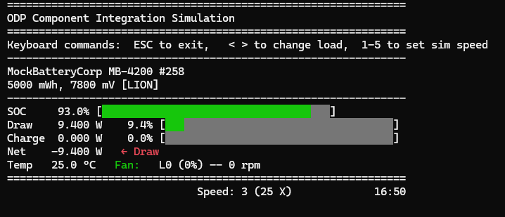
You can use the <> or left/right arrow keys to raise or lower the system load, and the number keys 1-5 to set the speed of time progression. The display updates in place, providing a more interactive experience. To toggle between this display and the logging mode, press d. When you are done, you can hit q or Esc to exit the simulation instead of resorting to ctrl-c.
You now have a interactive simulation application to test the behavior of your integrated components over a range of conditions. This type of app is a powerful tool for understanding how your components work together, and for identifying any issues that may arise in real-world usage.
Next up, we’ll use what we have learned from these interactions to devise some automated tests to validate the integration in an unattended way.
Integration Test
At long last, we are at the integration test portion of this exercise – along the way, we have created an integration that we can empirically run and evaluate, but a true integration test is automated, repeatable, and ideally part of a continuous integration (CI) process. We will create a test that runs the simulation for a short period of time, exercising the various components and their interactions, and then we will evaluate the results to ensure that they are as expected.
A true integration test is invaluable in an environment where components are being actively developed, as it provides a way to ensure that changes in one component do not inadvertently break the overall system. It also provides a way to validate that the system as a whole is functioning as intended, and that the various components are interacting correctly.
When things do begin to differ, one can use the interactive modes of an application such as this one to explore and understand the differences, and then make adjustments as needed.
Back to the DisplayRenderer
Our latest revision in the exercise was to create an in-place renderer that provides a more interactive experience. We can use the same mechanism to “render” to a testing construct that collects the results of simulated situations, evaluates them, and reports the results.
This is similar to the Test Observer pattern used in previous examples, although adapted here for this new context.
Feature selection
We don’t want our test mode “display” to be one of the toggle options of our simulation app. Rather, we want this to be selected at the start when we run the app in “integration-test” mode. So let’s define some feature flags that will define our starting modes:
So, before we even start defining our integration test support, let’s posit that this will be a separately selectable compile and runtime mode that we want to designate with a --features flag.
Our Cargo.toml already defines a [features] section that was mostly inherited from previous integration examples, and establishes the thread mode to use in different contexts.
We will keep that part of things intact so as not to interfere with the behavior of our dependent crates,
but we will extend it to introduce modes for log-mode, in-place-mode and integration-test mode, with in-place-mode being the default if no feature selection is made explicitly.
In Cargo.toml
[features]
default = ["in-place-mode"]
integration-test = ["std", "thread-mode"]
log-mode = ["std", "thread-mode"]
in-place-mode = ["std", "thread-mode"]
std = []
thread-mode = [
"mock_battery/thread-mode",
"mock_charger/thread-mode",
"mock_thermal/thread-mode"
]
noop-mode = [
"mock_battery/noop-mode",
"mock_charger/noop-mode",
"mock_thermal/noop-mode"
]
Then, in main.rs we can use this to choose which of our starting tasks we wish to launch:
#[embassy_executor::main]
async fn main(spawner: Spawner) {
#[cfg(feature = "integration-test")]
spawner.spawn(entry::entry_task_integration_test(spawner)).unwrap();
#[cfg(not(feature = "integration-test"))]
spawner.spawn(entry::entry_task_interactive(spawner)).unwrap();
}This will set apart the integration test into a separate launch we will establish in entry.rs as well as
further separating the selection of RenderMode::Log vs. RenderMode::InPlace as the default to start with when not in test mode.
In entry.rs, create the new entry task, and modify the render_task so that the RenderMode is passed in:
#![allow(unused)]
fn main() {
#[cfg(feature = "integration-test")]
#[embassy_executor::task]
pub async fn entry_task_integration_test(spawner: Spawner) {
println!("🚀 Integration test mode: integration project");
let shared = init_shared();
println!("setup_and_tap_starting");
let battery_ready = shared.battery_ready;
spawner.spawn(setup_and_tap_task(spawner, shared)).unwrap();
battery_ready.wait().await;
println!("init complete");
spawner.spawn(render_task(shared.display_channel, RenderMode::IntegrationTest)).unwrap();
}
#[embassy_executor::task]
pub async fn render_task(rx: &'static DisplayChannelWrapper, mode:RenderMode) {
let mut r = DisplayRenderer::new(mode);
r.run(rx).await;
}
}Then, let’s modify entry_task_interactive to respect the feature options for starting RenderMode as well:
#![allow(unused)]
fn main() {
#[embassy_executor::task]
pub async fn entry_task_interactive(spawner: Spawner) {
println!("🚀 Interactive mode: integration project");
let shared = init_shared();
println!("setup_and_tap_starting");
let battery_ready = shared.battery_ready;
spawner.spawn(setup_and_tap_task(spawner, shared)).unwrap();
battery_ready.wait().await;
println!("init complete");
spawner.spawn(interaction_task(shared.interaction_channel)).unwrap();
#[cfg(feature = "log-mode")]
let mode = RenderMode::Log;
#[cfg(not(feature = "log-mode"))]
#[cfg(feature = "in-place-mode")]
let mode = RenderMode::InPlace;
spawner.spawn(render_task(shared.display_channel, mode)).unwrap();
}
}RenderMode::IntegrationTest
We need to add the integration test mode to our RenderMode enum, and we need to create a placeholder for the rendering backend it will represent.
In events.rs, modify the RenderMode enum to now be:
#![allow(unused)]
fn main() {
pub enum RenderMode {
InPlace, // ANSI Terminal application
Log, // line-based console output
IntegrationTest // Collector/Reporter for testing
}
}Then create a new file in the display_render folder named integration_test_render.rs and give it this placeholder content for now:
#![allow(unused)]
fn main() {
use crate::display_render::display_render::{RendererBackend};
use crate::display_models::{StaticValues,DisplayValues, InteractionValues};
pub struct IntegrationTestBackend;
impl IntegrationTestBackend { pub fn new() -> Self { Self } }
impl RendererBackend for IntegrationTestBackend {
fn render_frame(&mut self, _dv: &DisplayValues, _ia: &InteractionValues) {
}
fn render_static(&mut self, _sv: &StaticValues) {
}
}
}this won’t actually do anything more yet other than satisfy our traits for a valid backend renderer.
we need to add this also to display_render/mod.rs:
// display_render
pub mod display_render;
pub mod log_render;
pub mod in_place_render;
pub mod integration_test_render;
In display_render.rs, we can import this:
#![allow(unused)]
fn main() {
use crate::display_render::integration_test_render::IntegrationTestBackend;
}and add it to the match statement of make_backend():
#![allow(unused)]
fn main() {
fn make_backend(mode: RenderMode) -> Box<dyn RendererBackend> {
match mode {
RenderMode::InPlace => Box::new(InPlaceBackend::new()),
RenderMode::Log => Box::new(LogBackend::new()),
RenderMode::IntegrationTest => Box::new(IntegrationTestBackend::new())
}
}
}now, we should be able to run in different modes from feature flags:
cargo run --features in-place-mode
or simply
cargo run
should give us our ANSI “In Place” app-style rendering.
cargo run --features log-mode
should give us our log mode output from the start.
cargo run --features integration-test
should not emit anything past the initial println! statements up through DoInit, since we have a non-functional rendering implementation in place here.
Next, let’s explore how we want to conduct our integration tests.
Integration Test Structure
Let’s imagine a framework where we can set our expectations for our integration behavior over time or between states, then set the integration into motion where these expectations are tested, and get a report on what has passed and failed. We can repeat different sets of such tests until we are satisfied we have tested everything we want to.
Such a framework would include a
-
a
TestReporterthat- tracks the start and end of a testing period, checking to see if the period is complete
- records the evaluations that are to occur for this time period, and marks them as pass of fail
- reports the outcomes of these tests
-
a
Test entryfunction that puts all of this into motion and defines the tests for each section and the scope of the tests.
Components of the TestReporter
- TestResult enum
- Test structure, name, result, message
- evaluation trait
- assert helpers
- collection of Tests
Let’s create test_reporter.rs and give it this content:
#![allow(unused)]
fn main() {
// test_reporter.rs
use std::fmt::{Display, Formatter};
use std::time::Instant;
/// Result of an evaluation.
#[derive(Debug, Clone, Copy, PartialEq, Eq)]
pub enum TestResult {
Pending,
Pass,
Fail,
}
impl Default for TestResult {
fn default() -> Self {
Self::Pending
}
}
impl Display for TestResult {
fn fmt(&self, f: &mut Formatter<'_>) -> std::fmt::Result {
match self {
TestResult::Pending => write!(f, "PENDING"),
TestResult::Pass => write!(f, "PASS"),
TestResult::Fail => write!(f, "FAIL"),
}
}
}
/// Per-test outcome produced by running an Evaluator.
#[derive(Debug, Clone)]
pub struct TestEval {
pub name: &'static str,
pub result: TestResult,
pub message: Option<String>,
// pub elapsed: Option<Duration>,
}
impl TestEval {
pub fn new(name: &'static str) -> Self {
Self { name, result: TestResult::Pending, message: None}
}
}
/// Pass to mark pass/fail and attach messages.
#[derive(Debug, Default)]
pub struct TestObserver {
result: TestResult,
message: Option<String>,
}
#[allow(unused)]
impl TestObserver {
// assume a test with no failures is considered passing.
pub fn new() -> Self { Self { result: TestResult::Pass, message: None } }
pub fn pass(&mut self) { self.result = TestResult::Pass; }
pub fn fail(&mut self, reason: impl Into<String>) {
self.result = TestResult::Fail;
self.message = Some(reason.into());
}
pub fn result(&self) -> TestResult { self.result }
pub fn message(&self) -> Option<&str> { self.message.as_deref() }
}
/// Trait each test implements. `run` should set PASS/FAIL on the observer.
pub trait Evaluator: Send {
fn name(&self) -> &'static str;
fn run(&mut self, obs: &mut TestObserver);
}
/// Helper: wrap a closure as an Evaluator.
pub struct FnEval {
name: &'static str,
f: Box<dyn FnMut(&mut TestObserver) + Send>,
}
impl FnEval {
pub fn new(name: &'static str, f: impl FnMut(&mut TestObserver) + Send + 'static) -> Self {
Self { name, f: Box::new(f) }
}
}
impl Evaluator for FnEval {
fn name(&self) -> &'static str { self.name }
fn run(&mut self, obs: &mut TestObserver) { (self.f)(obs) }
}
/// A collection of tests plus section timing/reporting.
pub struct TestReporter {
tests: Vec<Box<dyn Evaluator>>,
results: Vec<TestEval>,
section_start: Option<Instant>,
section_end: Option<Instant>,
}
#[allow(unused)]
impl TestReporter {
pub fn new() -> Self {
Self { tests: Vec::new(), results: Vec::new(), section_start: None, section_end: None }
}
/// Register any Evaluator.
pub fn add_test<E: Evaluator + 'static>(&mut self, eval: E) {
self.tests.push(Box::new(eval));
}
/// Convenience: register inline closures.
pub fn add_inline(&mut self, name: &'static str, f: impl FnMut(&mut TestObserver) + Send + 'static) {
self.add_test(FnEval::new(name, f));
}
/// Begin a new section: clears previous results but keeps registered tests
/// (so you can re-run same suite against evolving state). Call `clear_tests()`
/// if you want to rebuild the suite per section.
pub fn start_test_section(&mut self) {
self.results.clear();
self.section_start = Some(Instant::now());
self.section_end = None;
}
/// Optionally rebuild the suite.
pub fn clear_tests(&mut self) {
self.tests.clear();
self.results.clear();
}
/// Execute tests and capture results.
pub fn evaluate_tests(&mut self) {
self.results.clear();
for t in self.tests.iter_mut() {
let mut obs = TestObserver::new();
let t_start = Instant::now();
t.run(&mut obs);
// let elapsed = t_start.elapsed();
let result = obs.result;
let mut ev = TestEval::new(t.name());
ev.result = result;
ev.message = obs.message().map(|s| s.to_string());
// ev.elapsed = Some(elapsed);
self.results.push(ev);
}
}
/// End the section and print/report.
/// returns 0 on success or -1 on failures, which can be used as a reported error code for exit
pub fn end_test_section(&mut self) -> i32 {
self.section_end = Some(Instant::now());
self.print_report()
}
/// Aggregate and emit a summary report. Replace with your display backend as needed.
/// returns 0 on success or -1 on failures, which can be used as a reported error code for exit
pub fn print_report(&self) -> i32 {
let total = self.results.len();
let passed = self.results.iter().filter(|r| r.result == TestResult::Pass).count();
let failed = self.results.iter().filter(|r| r.result == TestResult::Fail).count();
let sec_elapsed = self.section_start
.zip(self.section_end)
.map(|(s, e)| e.duration_since(s));
println!("==================================================");
println!(" Test Section Report");
if let Some(d) = sec_elapsed {
println!(" Duration: {:?}\n", d);
}
for r in &self.results {
// let time = r.elapsed.map(|d| format!("{:?}", d)).unwrap_or_else(|| "-".into());
match (&r.result, &r.message) {
(TestResult::Pass, _) => {
println!("[PASS] {:<40}", r.name);
}
(TestResult::Fail, Some(msg)) => {
println!("[FAIL] {:<40} — {}", r.name, msg);
}
(TestResult::Fail, None) => {
println!("[FAIL] {:<40}", r.name);
}
(TestResult::Pending, _) => {
println!("[PEND] {:<40}", r.name);
}
}
}
println!("\n Summary: total={}, passed={}, failed={}", total, passed, failed);
println!("==================================================");
// return error code 0 == success, -1 == failure
if total == passed { 0 } else { -1 }
}
/// Retrieve results programmatically (e.g., to feed a UI).
pub fn results(&self) -> &[TestEval] { &self.results }
}
// Simple assertion macros
/// Test a boolean expression
/// Usage: expect!(obs, is_true, _optional_message);
#[macro_export]
macro_rules! expect {
($obs:expr, $cond:expr, $($msg:tt)*) => {{
if !($cond) {
$obs.fail(format!($($msg)*));
return;
}
}};
}
/// Compare two values for equality
/// Usage: expect_eq!(obs, actual, expected, _optional_message);
#[macro_export]
macro_rules! expect_eq {
($obs:expr, $left:expr, $right:expr $(, $($msg:tt)*)? ) => {{
if $left != $right {
let msg = format!(
concat!("expected == actual, but got:\n expected: {:?}\n actual: {:?}", $(concat!("\n ", $($msg)*))?),
&$right, &$left
);
$obs.fail(msg);
return;
}
}};
}
/// Compare two numbers after rounding to `places` decimal places.
/// Usage: expect_to_decimal!(obs, actual, expected, places);
#[macro_export]
macro_rules! expect_to_decimal {
($obs:expr, $actual:expr, $expected:expr, $places:expr $(,)?) => {{
// Work in f64 for better rounding behavior, then compare the rounded integers.
let a_f64: f64 = ($actual) as f64;
let e_f64: f64 = ($expected) as f64;
let places_u: usize = ($places) as usize;
let scale: f64 = 10f64.powi(places_u as i32);
let a_round_i = (a_f64 * scale).round() as i64;
let e_round_i = (e_f64 * scale).round() as i64;
if a_round_i == e_round_i {
$obs.pass();
} else {
// Nice message with the same precision the comparison used
let a_round = a_round_i as f64 / scale;
let e_round = e_round_i as f64 / scale;
let msg = format!(
"expected ~= {e:.prec$} but got {a:.prec$} (rounded to {places} dp; {e_round:.prec$} vs {a_round:.prec$})",
e = e_f64,
a = a_f64,
e_round = e_round,
a_round = a_round,
prec = places_u,
places = places_u
);
$obs.fail(&msg);
}
}};
}
/// Syntactic sugar to add inline tests:
/// add_test!(reporter, "Name", |obs| { /* ... */ });
#[macro_export]
macro_rules! add_test {
($reporter:expr, $name:expr, |$obs:ident| $body:block) => {{
$reporter.add_inline($name, move |$obs: &mut TestObserver| $body);
}};
}
}This establishes the feature framework we discussed above. It is able to collect and report on test evaluations for one or many test sections, and provides some helpful macros such as add_test! to register a closure as the evaluation function as well as some assertion macros designed to use with the TestObserver.
Add this as a module also to main.rs:
#![allow(unused)]
fn main() {
mod test_reporter;
}Wiring it into the IntegrationTest DisplayRenderer
Central to our plan is the idea that we can make a DisplayRenderer variant that will feed us the results of the simulation as it runs. We can then evaluate these values in context and assign Pass/Fail results to the TestReporter and print out the final tally.
To do this, we need to “tap” the render_static and render_frame traits of our IntegrationTestBackend and feed this data into where we are running the test code.
Adding the TestTap
Let’s replace our placeholder integration_test_render.rs file with this new version:
#![allow(unused)]
fn main() {
use crate::display_render::display_render::{RendererBackend};
use crate::display_models::{StaticValues,DisplayValues, InteractionValues};
use ec_common::mutex::{Mutex, RawMutex};
pub trait TestTap: Send + 'static {
fn on_static(&mut self, sv: &StaticValues);
fn on_frame(&mut self, dv: &DisplayValues);
}
struct NullTap;
#[allow(unused)]
impl TestTap for NullTap {
fn on_static(&mut self, _sv: &StaticValues) {}
fn on_frame(&mut self, _dv: &DisplayValues) {}
}
pub struct IntegrationTestBackend {
tap: Mutex<RawMutex, Box<dyn TestTap + Send>>
}
impl IntegrationTestBackend {
pub fn new() -> Self {
Self {
tap: Mutex::new(Box::new(NullTap))
}
}
}
impl RendererBackend for IntegrationTestBackend {
fn render_frame(&mut self, dv: &DisplayValues, _ia: &InteractionValues) {
let mut t = self.tap.try_lock().expect("tap locked in another task?");
t.on_frame(dv);
}
fn render_static(&mut self, sv: &StaticValues) {
let mut t = self.tap.try_lock().expect("tap locked in another task?");
t.on_static(sv);
}
#[cfg(feature = "integration-test")]
fn set_test_tap(&mut self, tap: Box<dyn TestTap + Send>) {
let mut guard = self.tap.try_lock().expect("tap locked in another task?");
*guard = tap;
}}
}You will see that we have defined a TestTap trait that provides us with the callback methods we are looking for to feed our test running code. We’ve given a concrete implementation NullTap to use as a no-op stub to hold fort until we replace it with set_test_tap() later.
We will need to make some changes to our display_render.rs file to accommodate this. Open up that file and add the following:
#![allow(unused)]
fn main() {
use crate::display_render::integration_test_render::IntegrationTestBackend;
#[cfg(feature = "integration-test")]
use crate::display_render::integration_test_render::TestTap;
}Change the trait definition for RendererBackend to now be:
#![allow(unused)]
fn main() {
// Define a trait for the interface for a rendering backend
pub trait RendererBackend : Send + Sync {
fn on_enter(&mut self, _last: Option<&DisplayValues>) {}
fn on_exit(&mut self) {}
fn render_frame(&mut self, dv: &DisplayValues, ia: &InteractionValues);
fn render_static(&mut self, sv: &StaticValues);
#[cfg(feature = "integration-test")]
fn set_test_tap(&mut self, _tap: Box<dyn TestTap + Send>) {}
}
}This gives us the ability to set the test tap, and it defaults to nothing unless we implement it, as we have done already in integration_test_render.rs.
Now add this function to the impl DisplayRender block:
#![allow(unused)]
fn main() {
#[cfg(feature = "integration-test")]
pub fn set_test_tap<T>(&mut self, tap: T) -> Result<(), &'static str>
where
T: TestTap + Send + 'static,
{
if self.mode != RenderMode::IntegrationTest {
return Err("Renderer is not in Integration Test mode");
}
self.backend.set_test_tap(Box::new(tap));
Ok(())
}
}Using these changes in test code
Now we can start to build in the test code itself.
We’ll create a new file for this: integration_test.rs and give it this content:
#![allow(unused)]
fn main() {
#[cfg(feature = "integration-test")]
pub mod test_module {
use crate::test_reporter::test_reporter::TestObserver;
use crate::test_reporter::test_reporter::TestReporter;
use crate::{add_test,expect, expect_eq};
use crate::display_models::{DisplayValues, StaticValues};
use crate::display_render::integration_test_render::TestTap;
use crate::entry::DisplayChannelWrapper;
use crate::display_render::display_render::DisplayRenderer;
use crate::events::RenderMode;
#[embassy_executor::task]
pub async fn integration_test(rx: &'static DisplayChannelWrapper) {
let mut reporter = TestReporter::new();
reporter.start_test_section();
struct ITest {
reporter: TestReporter,
first_time: Option<u64>,
test_time_ms: u64,
saw_static: bool,
frame_count: i16
}
impl ITest {
pub fn new() -> Self {
Self {
reporter: TestReporter::new(),
first_time: None,
test_time_ms: 0,
saw_static: false,
frame_count: 0
}
}
}
impl TestTap for ITest {
fn on_static(&mut self, sv: &StaticValues) {
add_test!(self.reporter, "Static Values received", |obs| {
obs.pass();
});
self.saw_static = true;
println!("🔬 Integration testing starting...");
}
fn on_frame(&mut self, dv: &DisplayValues) {
let load_ma= dv.load_ma;
let first = self.first_time.get_or_insert(dv.sim_time_ms as u64);
self.test_time_ms = (dv.sim_time_ms as u64).saturating_sub(*first);
if self.frame_count == 0 {
// ⬇️ Take snapshots so the closure doesn't capture `self`
let saw_static_snapshot = self.saw_static;
let load_at_start = load_ma;
let expected = 1200;
add_test!(self.reporter, "First Test Data Frame received", |obs| {
expect!(obs, saw_static_snapshot, "Static Data should have come first");
expect_eq!(obs, load_at_start, expected, "Load value at start");
obs.pass();
});
}
self.frame_count += 1;
if self.test_time_ms > 5_000 {
// `self` is fine to use here; the borrow from add_test! ended at the call.
self.reporter.evaluate_tests();
self.reporter.print_report();
std::process::exit(0);
}
}
}
let mut r = DisplayRenderer::new(RenderMode::IntegrationTest);
r.set_test_tap(ITest::new()).unwrap();
r.run(rx).await;
}
}
}Note that we’ve wrapped this entire file content as a module and gated it behind #[cfg(feature = "integration-test")] so that it is only valid in integration-test mode.
add this module to main.rs
#![allow(unused)]
fn main() {
mod integration_test;
}and in entry.rs, add the import for this task:
#![allow(unused)]
fn main() {
#[cfg(feature = "integration-test")]
use crate::integration_test::test_module::integration_test;
}also in entry.rs, replace the spawn of render_task with the spawn to integration_test, passing the display channel that will continue to be used for our tapped Display messaging which will now route to our test code.
#![allow(unused)]
fn main() {
#[cfg(feature = "integration-test")]
#[embassy_executor::task]
pub async fn entry_task_integration_test(spawner: Spawner) {
println!("🚀 Integration test mode: integration project");
let shared = init_shared();
println!("setup_and_tap_starting");
let battery_ready = shared.battery_ready;
spawner.spawn(setup_and_tap_task(spawner, shared)).unwrap();
battery_ready.wait().await;
println!("init complete");
spawner.spawn(integration_test(shared.display_channel)).unwrap();
}
}A cargo run --features integration-test should produce the following output:
Running `C:\Users\StevenOhmert\odp\ec_examples\target\debug\integration_project.exe`
🚀 Integration test mode: integration project
setup_and_tap_starting
⚙️ Initializing embedded-services
⚙️ Spawning battery service task
⚙️ Spawning battery wrapper task
🧩 Registering battery device...
🧩 Registering charger device...
🧩 Registering sensor device...
🧩 Registering fan device...
🔌 Initializing battery fuel gauge service...
Setup and Tap calling ControllerCore::start...
In ControllerCore::start()
spawning controller_core_task
spawning start_charger_task
spawning charger_policy_event_task
spawning integration_listener_task
init complete
🥺 Doing battery service startup -- DoInit followed by PollDynamicData
✅ Charger is ready.
🥳 >>>>> ping has been called!!! <<<<<<
🛠️ Charger initialized.
battery-service DoInit -> Ok(Ack)
🔬 Integration testing starting...
==================================================
Test Section Report
[PASS] Static Values received (1µs)
[PASS] First Test Data Frame received (400ns)
Summary: total=2, passed=2, failed=0
==================================================
That’s a good proof-of-concept start. Let’s create some meaningful tests now.
Adding Meaningful Tests
We have the ability to run the app as an interactive simulation, including the logging mode that will output a running record of the changes over time as we change the load.
So, it makes sense to derive some sense of expected behavior from these results and model tests that correspond to this.
What are we really testing?
Of course, this is a simulated integration of virtual components – running simulation algorithms as stand-ins for actual physical behaviors – so when we run our tests, we are also testing the realism of these sims. Although reasonable effort has been made to account for the physics of temperature change, battery life, and so on, it should not be expected that these are precisely accurate. In a real integration, you don’t get to change the effects of physics – so we’ll test against the physical reality as it is presented to us, realistic or otherwise.
Running with the default configurations as we have built them in this example, we can observe the battery starts off at 100% SOC and we have a starting default system load/draw of 9.4W. The battery thus discharges to a point where the charger activates below 90%, then charges back up to 100%, detaches the charger, and the cycle repeats.
If we increase the load during any of this, the battery discharges faster, and the temperature rises more quickly and at the configured point of 28 degrees celsius, the fan turns on to facilitate cooling. The ability of the fan to counter the load depends upon the continued draw level, and whether or not the charger is running. If cooling is sufficient, the fan slows, and under lower load, will turn off.
As we’ve written it, the test context does not have the ability to change the simulated time multiplier the way the interactive context allows, so all simulation time for the test runs at the pre-configured level 3 (25X).
Running faster
Since this is a test, we don’t need to dally. Let’s make a change so that the default level for the integration-test mode is level 5 (100X). In controller_core.rs add the following lines at the top of the controller_core_task so that this executes once at the start before entering the event loop:
#![allow(unused)]
fn main() {
#[cfg(feature = "integration-test")]
{
let core = core_mutex.lock().await;
core.sysobs.set_speed_number(5).await;
}
}Checking static, then stepwise events
Our initial tests already establish that static data is received, and verifies the one-time-at-the-start behavior is respected, but we don’t check any values. This is largely superfluous, of course, but we should verify anyway.
Following this first event, we need a good way to know where we are at in the flow of subsequent events so that we can properly evaluate and direct the context at the time.
Let’s update our current integration_test.rs code with a somewhat revised version:
#![allow(unused)]
fn main() {
#[cfg(feature = "integration-test")]
pub mod integration_test {
use crate::test_reporter::test_reporter::TestObserver;
use crate::test_reporter::test_reporter::TestReporter;
use crate::{add_test,expect, expect_eq};
use crate::display_models::{DisplayValues, StaticValues};
use crate::display_render::integration_test_render::TestTap;
use crate::entry::DisplayChannelWrapper;
use crate::display_render::display_render::DisplayRenderer;
use crate::events::RenderMode;
#[allow(unused)]
#[derive(Debug)]
enum TestStep {
None,
CheckStartingValues,
CheckChargerAttach,
RaiseLoadAndCheckTemp,
RaiseLoadAndCheckFan,
LowerLoadAndCheckCooling,
EndAndReport
}
#[embassy_executor::task]
pub async fn integration_test(rx: &'static DisplayChannelWrapper) {
struct ITest {
reporter: TestReporter,
first_time: Option<u64>,
test_time_ms: u64,
saw_static: bool,
frame_count: i16,
step: TestStep,
}
impl ITest {
pub fn new() -> Self {
let mut reporter = TestReporter::new();
reporter.start_test_section(); // start out with a new section
Self {
reporter,
first_time: None,
test_time_ms: 0,
saw_static: false,
frame_count: 0,
step: TestStep::None
}
}
// -- Individual step tests ---
fn check_starting_values(&mut self, draw_watts:f32) -> TestStep {
let reporter = &mut self.reporter;
add_test!(reporter, "Check Starting Values", |obs| {
expect_eq!(obs, draw_watts, 9.4);
obs.pass();
});
TestStep::EndAndReport
}
// --- final step to report and exit --
fn end_and_report(&mut self) {
let reporter = &mut self.reporter;
reporter.evaluate_tests();
reporter.end_test_section();
std::process::exit(0);
}
}
impl TestTap for ITest {
fn on_static(&mut self, sv: &StaticValues) {
let _ = sv;
add_test!(self.reporter, "Static Values received", |obs| {
obs.pass();
});
self.saw_static = true;
println!("🔬 Integration testing starting...");
}
fn on_frame(&mut self, dv: &DisplayValues) {
let reporter = &mut self.reporter;
let first = self.first_time.get_or_insert(dv.sim_time_ms as u64);
self.test_time_ms = (dv.sim_time_ms as u64).saturating_sub(*first);
if self.frame_count == 0 {
// Take snapshots so the closure doesn't capture `self`
let saw_static = self.saw_static;
add_test!(reporter, "First Test Data Frame received", |obs| {
expect!(obs, saw_static, "Static Data should have come first");
obs.pass();
});
self.step = TestStep::CheckStartingValues;
}
println!("Step {:?}", self.step);
match self.step {
TestStep::CheckStartingValues => {
let draw_watts = dv.draw_watts;
self.step = self.check_starting_values(draw_watts);
},
TestStep::EndAndReport => self.end_and_report(),
_ => {}
}
self.frame_count += 1;
}
}
let mut r = DisplayRenderer::new(RenderMode::IntegrationTest);
r.set_test_tap(ITest::new()).unwrap();
r.run(rx).await;
}
}
}This introduces a few notable changes.
We’ve introduced an enum, TestStep, that names a series of proposed points in the flow that we wish to make measurements. For now, we are only using the first of these CheckStartingValues, but the pattern will remain the same for any subsequent steps. We have a corresponding check_starting_values method defined that conducts the actual test. Note the end_and_report method also, which is the last step of the flow and signals it is time to report the test results and exit.
This revised version does little more just yet than our previous one, but it sets the stage for stepwise updates.
cargo run --features integration-test:
🚀 Integration test mode: integration project
setup_and_tap_starting
⚙️ Initializing embedded-services
⚙️ Spawning battery service task
⚙️ Spawning battery wrapper task
🧩 Registering battery device...
🧩 Registering charger device...
🧩 Registering sensor device...
🧩 Registering fan device...
🔌 Initializing battery fuel gauge service...
Setup and Tap calling ControllerCore::start...
In ControllerCore::start()
spawning controller_core_task
spawning start_charger_task
spawning charger_policy_event_task
spawning integration_listener_task
init complete
🥺 Doing battery service startup -- DoInit followed by PollDynamicData
✅ Charger is ready.
🥳 >>>>> ping has been called!!! <<<<<<
🛠️ Charger initialized.
battery-service DoInit -> Ok(Ack)
🔬 Integration testing starting...
Step CheckStartingValues
Step EndAndReport
==================================================
Test Section Report
[PASS] Static Values received (700ns)
[PASS] First Test Data Frame received (400ns)
[PASS] Check Starting Values (300ns)
Summary: total=3, passed=3, failed=0
==================================================
Before we move on with the next steps, let’s finish out the perfunctory tasks of verifying our static data and a couple more starting values:
Replace the current on_static method with this one:
#![allow(unused)]
fn main() {
fn on_static(&mut self, sv: &StaticValues) {
let reporter = &mut self.reporter;
let mfg_name = sv.battery_mfr.clone();
let dev_name = sv.battery_name.clone();
let chem = sv.battery_chem.clone();
let cap_mwh = sv.battery_dsgn_cap_mwh;
let cap_mv = sv.battery_dsgn_voltage_mv;
add_test!(reporter, "Static Values received", |obs| {
expect_eq!(obs, mfg_name.trim_end_matches('\0'), "MockBatteryCorp");
expect_eq!(obs, dev_name.trim_end_matches('\0'), "MB-4200");
expect_eq!(obs, chem.trim_end_matches('\0'), "LION");
expect_eq!(obs, cap_mwh, 5000);
expect_eq!(obs, cap_mv, 7800);
});
self.saw_static = true;
println!("🔬 Integration testing starting...");
}
}and we’ll check some more of the starting values. Change the member function check_starting_values() to this version:
#![allow(unused)]
fn main() {
fn check_starting_values(&mut self, soc:f32, draw_watts:f32, charge_watts:f32, temp_c:f32, fan_rpm:u16) -> TestStep {
let reporter = &mut self.reporter;
add_test!(reporter, "Check Starting Values", |obs| {
expect_eq!(obs, soc, 100.0);
expect_eq!(obs, draw_watts, 9.4);
expect_eq!(obs, charge_watts, 0.0);
expect_to_decimal!(obs, temp_c, 24.6, 1);
expect_eq!(obs, fan_rpm, 0);
});
//TestStep::CheckChargerAttach
TestStep::EndAndReport
}
}and change the match arm to call it like this:
#![allow(unused)]
fn main() {
TestStep::CheckStartingValues => {
let draw_watts = dv.draw_watts;
let charge_watts = dv.charge_watts;
let temp_c = dv.temp_c;
let soc = dv.soc_percent;
let fan_rpm = dv.fan_rpm;
self.step = self.check_starting_values(soc, draw_watts, charge_watts, temp_c, fan_rpm);
},
}Now we can be reasonably confident that we are starting out as expected before continuing.
A note on test value measurements
In our starting values test we check the starting temperature pretty closely (to within 1 decimal position), but in other tests we look for a more general threshold of range.
In the case of starting values, we know what this should be because it comes from the scenario configurations, and we can be confident in the deterministic outcome. In other examples, we can’t be entirely sure of the vagaries of time – even in a simulation, what with differing host computer speeds, drifts in clocks, and inevitable inaccuracies in our simulated physics. So we “loosen the belt” a bit more in these situations.
Checking Charger Attachment
Let’s continue on with the next step we’ve outlined in our TestStep series: TestStep::CheckChargerAttach.
To do this, create a new member function for this:
#![allow(unused)]
fn main() {
fn check_charger_attach(&mut self, mins_passed: f32, soc:f32, charge_watts:f32) -> TestStep {
let reporter = &mut self.reporter;
// Fail if we don't see our starting conditions within a reasonable time
if mins_passed > 30.0 { // should occur before 30 minutes simulation time
add_test!(reporter, "Attach Charger", |obs| {
obs.fail("Time expired waiting for attach");
});
}
// wait until we see evidence of charger attachment
if charge_watts == 0.0 {
return TestStep::CheckChargerAttach; // stay on this task
}
add_test!(reporter, "Check Charger Attachment", |obs| {
expect!(obs, soc <= 90.0, "Attach expected <= 90% SOC");
});
// TestStep::RaiseLoadAndCheckTemp // go to next step
TestStep::EndAndReport
}
}This is a little different because it first checks for qualifying (or disqualifying error) conditions before it begins the actual test closure.
First, it checks to see if we’ve timed out – using simulation time, and assuming the starting values that we’ve already verified, we expect the battery to discharge to the attach point in under 30 minutes. If this condition fails, we create a directly failing test to report it.
We then check to see if the charger is attached, which is evidenced by charge_watts > 0.0 until this is true, we return TestStep::CheckChargerAttach so that we continue to be called each frame until then.
Once these conditional checks are done, we can test what it means to be in attached state and proceed to the next step, which in this case is EndAndReport until we add another test.
On that note, edit the return of check_starting_values() to now be TestStep::CheckChargerAttach so that it chains to this one.
Now, in the match arms for this, add this caller:
#![allow(unused)]
fn main() {
TestStep::CheckChargerAttach => {
let mins_passed = dv.sim_time_ms / 60_000.0;
let soc = dv.soc_percent;
let charge_watts = dv.charge_watts;
self.step = self.check_charger_attach(mins_passed, soc, charge_watts);
},
}finally, remove this println! because these will start to become annoying at this point:
#![allow(unused)]
fn main() {
println!("Step {:?}", self.step);
}and when run with cargo run --features integration-test you should see:
🔬 Integration testing starting...
☄ attaching charger
==================================================
Test Section Report
[PASS] Static Values received
[PASS] First Test Data Frame received
[PASS] Check Starting Values
[PASS] Check Charger Attachment
Summary: total=4, passed=4, failed=0
==================================================
Next, we’ll look at what the effects of increasing the system load have to our scenario, but first we need to provide a mechanism for that.
Affecting Change in the tests
For our next test, we want to raise the system load and then see how that affects temperature (it should rise).
We don’t currently have a way to tell the simulation to raise the load. But in interactive mode we can, and we did that by sending InteractionEvent messages. Let’s do that here. We’ll need to pass in the InteractionChannelWrapper we need for sending these messages into the integration_test() function.
Start by adding these imports:
#![allow(unused)]
fn main() {
use crate::entry::InteractionChannelWrapper;
use ec_common::espi_service::EventChannel;
use crate::events::InteractionEvent;
}Then, change the signature for interaction_test() to accept the new parameter:
#![allow(unused)]
fn main() {
#[embassy_executor::task]
pub async fn integration_test(rx: &'static DisplayChannelWrapper, tx:&'static InteractionChannelWrapper) {
}Now, unlike the rx parameter that we use within the body of the function, we need this tx parameter available to us while we are in the test code – and therefore the ITest structure itself, so we need to add it as a member and pass it in on the constructor:
#![allow(unused)]
fn main() {
struct ITest {
reporter: TestReporter,
tx: &'static InteractionChannelWrapper,
...
}
}and
#![allow(unused)]
fn main() {
impl ITest {
pub fn new(tx:&'static InteractionChannelWrapper) -> Self {
let mut reporter = TestReporter::new();
reporter.start_test_section(); // start out with a new section
Self {
reporter,
tx,
...
}and pass tx in the ITest constructor in this code at the bottom of the integration_test() function:
#![allow(unused)]
fn main() {
let mut r = DisplayRenderer::new(RenderMode::IntegrationTest);
r.set_test_tap(ITest::new(tx)).unwrap();
r.run(rx).await;
}Note that the rx (Display) Channel is consumed entirely within the DisplayRenderer run loop, whereas our tx (Interaction) Channel must be available to us in ITest for ad-hoc sending of InteractionEvent messages within our test steps, thus the way we’ve bifurcated the usage of these here.
Now we are set up to call on interaction event to increase and decrease the load, as we will use in the next test.
Our TestStep enum for this is RaiseLoadAndCheckTemp.
Create a new member function to handle this:
#![allow(unused)]
fn main() {
fn raise_load_and_check_temp(&mut self, mins_passed:f32, draw_watts: f32, temp_c:f32) -> TestStep {
let reporter = &mut self.reporter;
TestStep::EndAndReport
}
}We’ll fill it out later. First, we need to add some helper members we can use to track time and temperature.
Add these members to the ITest struct:
#![allow(unused)]
fn main() {
mark_time: Option<f32>,
mark_temp: Option<f32>,
}and initialize them as None:
#![allow(unused)]
fn main() {
mark_time: None,
mark_temp: None,
}Now, fill out our raise_load_and_check_temp function to look like this:
#![allow(unused)]
fn main() {
fn raise_load_and_check_temp(&mut self, mins_passed:f32, draw_watts: f32, temp_c:f32) -> TestStep {
let reporter = &mut self.reporter;
if self.mark_time == None {
self.mark_time = Some(mins_passed);
self.mark_temp = Some(temp_c);
}
if draw_watts < 20.0 { // raise to something above 20 then stop pumping it up
let _ = self.tx.try_send(InteractionEvent::LoadUp);
return TestStep::RaiseLoadAndCheckTemp
}
let mt = *self.mark_time.get_or_insert(mins_passed);
let time_at_charge = if mins_passed > mt { mins_passed - mt } else { 0.0 };
if time_at_charge > 0.5 { // after about 30 seconds, check temperature
let temp_raised = self.mark_temp.map_or(0.0, |mt| if temp_c > mt { temp_c - mt } else { 0.0 });
add_test!(reporter, "Temperature rises on charge", |obs| {
expect!(obs, temp_raised > 1.5, "Temp should rise noticeably");
});
} else {
// keep going
return TestStep::RaiseLoadAndCheckTemp
}
// reset in case we want to use these again later
self.mark_temp = None;
self.mark_time = None;
// TestStep::RaiseLoadAndCheckFan // next step
TestStep::EndAndReport
}
}What we do here is mark the time when we first get in, then we bump up the the load using our new tx member until we see that the load is something above 20w. At that point we check the time to see if at least 1/2 a minute has passed. Until these conditions are met, we keep returning TestStep::RaiseLoadAndCheckTemp to keep us evaluating this state. Once there, we check how high the temperature has risen since the last check, relative to the marked baseline. We expect it to be around 2 degrees, give or take, so we’ll check for 1.5 degrees or more as our test. We then go to the next step (for now, EndAndReport), but before we do we reset our Option marks in case we want to reuse them in subsequent tests.
Remember to change the return value of check_charger_attach to go to TestStep::RaiseLoadAndCheckTemp also, or this test won’t fire.
Then add the calling code in the match arms section below:
#![allow(unused)]
fn main() {
TestStep::RaiseLoadAndCheckTemp => {
let mins_passed = dv.sim_time_ms / 60_000.0;
let load_watts = dv.draw_watts;
let temp_c = dv.temp_c;
self.step = self.raise_load_and_check_temp(mins_passed, load_watts, temp_c);
},
}Checking the Fan
The next test we’ll create is similar, but in this case, we’ll raise the load (and heat) significantly enough for the system fan to kick in.
Create the member function we’ll need for this. it will look much like the previous one in many ways:
#![allow(unused)]
fn main() {
fn raise_load_and_check_fan(&mut self, mins_passed:f32, draw_watts:f32, temp_c:f32, fan_rpm:u16) -> TestStep {
let reporter = &mut self.reporter;
// record time we started this
if self.mark_time == None {
self.mark_time = Some(mins_passed);
}
if draw_watts < 39.0 { // raise to maximum
let _ = self.tx.try_send(InteractionEvent::LoadUp);
return TestStep::RaiseLoadAndCheckFan
}
let mt = *self.mark_time.get_or_insert(mins_passed);
let time_elapsed = if mins_passed > mt { mins_passed - mt } else { 0.0 };
if time_elapsed > 0.25 && fan_rpm == 0 { // this should happen relatively quickly
add_test!(reporter, "Timed out waiting for fan", |obs| {
obs.fail("Time expired");
});
return TestStep::EndAndReport // quit tests if we timeout
}
if fan_rpm > 0 {
add_test!(reporter, "Temperature is warm", |obs| {
expect!(obs, temp_c >= 28.0, "temp below fan on range");
});
add_test!(reporter, "Fan turns on", |obs| {
obs.pass();
});
} else {
// keep going
return TestStep::RaiseLoadAndCheckFan
}
// reset in case we want to use these again later
self.mark_temp = None;
self.mark_time = None;
// TestStep::LowerLoadAndCheckCooling
TestStep::EndAndReport
}
}add the calling case to the match arm:
#![allow(unused)]
fn main() {
TestStep::RaiseLoadAndCheckFan => {
let mins_passed = dv.sim_time_ms / 60_000.0;
let draw_watts = dv.draw_watts;
let temp_c = dv.temp_c;
let fan_rpm = dv.fan_rpm;
self.step = self.raise_load_and_check_fan(mins_passed, draw_watts, temp_c, fan_rpm);
},
}Don’t forget to update the next step return of the previous step so that it carries forward to this one.
Time to Chill
Great! Now, let’s make sure the temperature goes back down with less demand on the system and that the fan backs off when cooling is complete.
Create the member function
#![allow(unused)]
fn main() {
fn lower_load_and_check_cooling(&mut self, mins_passed:f32, draw_watts:f32, temp_c:f32, fan_rpm:u16) -> TestStep {
let reporter = &mut self.reporter;
// record time and temp when we started this
if self.mark_time == None {
self.mark_time = Some(mins_passed);
self.mark_temp = Some(temp_c);
}
// drop load back to low
if draw_watts > 10.0 {
let _ = self.tx.try_send(InteractionEvent::LoadDown);
return TestStep::LowerLoadAndCheckCooling
}
// wait a bit
let mark_time = *self.mark_time.get_or_insert(mins_passed);
let diff = mins_passed - mark_time;
if diff < 60.0 { // wait for an hour for it to cool all the way
return TestStep::LowerLoadAndCheckCooling
}
add_test!(reporter, "Cooled", |obs| {
expect!(obs, draw_watts < 10.0, "Load < 10 W");
expect!(obs, temp_c < 25.5, "Temp is < 25.5");
});
add_test!(reporter, "Fan turns off", |obs| {
expect_eq!(obs, fan_rpm, 0);
});
// reset in case we want to use these again later
self.mark_temp = None;
self.mark_time = None;
TestStep::EndAndReport
}
}and the caller in the match arm:
#![allow(unused)]
fn main() {
TestStep::LowerLoadAndCheckCooling => {
let mins_passed = dv.sim_time_ms / 60_000.0;
let draw_watts = dv.draw_watts;
let temp_c = dv.temp_c;
let fan_rpm = dv.fan_rpm;
self.step = self.lower_load_and_check_cooling(mins_passed, draw_watts, temp_c, fan_rpm);
},
}And again, remember to update the return value for the next step of the load_and_check_fan method to be TestStep::LowerLoadAndCheckCooling so that it chains to this one properly.
Your cargo run --features integration-test should now complete in about 40 seconds and look like this (your output timing may vary slightly):
==================================================
Test Section Report
Duration: 35.4803276s
[PASS] Static Values received
[PASS] First Test Data Frame received
[PASS] Check Starting Values
[PASS] Check Charger Attachment
[PASS] Temperature rises on charge
[PASS] Temperature is warm
[PASS] Fan turns on
[PASS] Cooled
[PASS] Fan turns off
Summary: total=9, passed=9, failed=0
==================================================
Summary Thoughts
Congratulations on your success in building and integrating, understanding, and testing virtual components using the ODP framework!
Along the way, we became familiar with the ODP repositories used for making EC components and how to structure them to work together.
We made some mistakes and learned how to correct for them. We saw how there are multiple ways in which the ODP resources can be leveraged and customized and which services are available to give us consistent behaviors right out of the box.
There are, of course, a number of things that one would do differently if they were working with actual hardware and building for an actual system.
For starters, much of the behavioral code we created in these exercises needed to substitute simulated time and physical responses that would “just happen” with real hardware in real time, and real-world physics may differ from our simplified models here.
We use println! pretty liberally in our examples – this is fine since we are building for a std environment with these apps currently, but when migrating to a target build, these will need to replaced by log::debug! or info! and limited in context.
With the simplistic integration we have here, the battery is always the source of power – it will charge, but if the load exceeds the charger ability, the battery will eventually fail even when the device is presumably plugged in. This is an artifact of our simplified model. A real Embedded Controller integrations power-path control so that mains input can bypass the battery when not available. Readers are encouraged to look at the
examples in the embedded-services repository at examples/std/src/bin/type_c and examples/std/src/bin/power_policy.rs for examples of resources that can be used in extending the integration to support a “plugged-in” mode.
Best Practices
- Consolidate locks: When reading multiple fields from a shared Mutex, prefer taking one short lock and copying local values rather than multiple fine-grained locks.
- Channels in tests: Use
try_sendin test harnesses to avoid hangs, but usesendin production code where reliability matters.- Structured logging: Replace
println!withlog::info!orlog::debug!and use consistent tags so output can be filtered in embedded builds.- Incremental layering: Build one subsystem at a time, confirm behavior in isolation, then integrate. It avoids compounding errors.
- Keep tests near the code: Even trivial modules benefit from local unit tests; it makes later migration to embedded hardware smoother.
Where do we go from here?
There are some key steps ahead before one can truly claim to have an EC integration ready:
- Hardware - We have not yet targeted for actual embedded hardware – whether simulated behavior is used or not – that is coming up in the next set of exercises. This could target an actual hardware board or perhaps a QEMU virtual system as an intermediary step.
- Standard Bus Interface - To connect the EC into a system, we would need to adopt a standard bus interface – most likely ACPI
- Security - We have conceptually touched upon security, but have not made any implementation efforts to support such mechanisms. A real-world system must address these. In environments that support it, a Hafnium-based hypervisor implementation for switching EC services into context is recommended.
The ODP EC Test App
Once a complete EC is constructed, there is a very nice test app produced by the ODP that can be used to validate that the ACPI plumbing is correct and the EC responds to calls with the expected arguments in and return values back.
At this point, you have the building blocks in hand to extend your virtual EC toward this validation path by adding ACPI plumbing on top of the Rust components we’ve built and exposing them in a QEMU or hardware container.
The ec-test-app repo even includes sample ACPI tables (thermal + notification examples) to show how the methods are expected to be defined. That could be a starting point for the essential bridge between the Rust-based EC simulation examples we’ve worked with, and the Windows validation world for a true device.
Creating a Virtual Laptop
What would it take to create a virtual laptop—a system that feels like a real platform, but is built entirely from emulated pieces?
This is an ambitious goal, but it’s a natural culmination of the topics we’ve covered. By combining a virtualized Embedded Controller (EC), a Patina boot firmware layer, and an emulated host environment, we can build a system that exercises nearly the same firmware flows as real hardware.
Step 1: Build an EC
The heart of any modern laptop design is the Embedded Controller. Our first step is to build one using ODP components:
- Option A: Building onto a development board.
- If you are able to source a SOC development board with all the necessary component hardware – then great!
- If this is hard to come by, you could use a commodity development board and implement simulated components, as we have done in the examples in this guide. Although there would not be any real hardware action, the logical behaviors would be the same and the virtual laptop would operate the same way.
- Option B: Virtualized microcontroller Similar to Option A, but instead of a commodity board, you build into a virtual container that emulates a popular microcontroller. This makes the “virtual laptop” self-contained, since the EC never leaves your development workstation.
In either case, the EC hosts the battery, charger, and thermal components we’ve already worked through.
Step 2: Implement Components
Populate the EC with the devices you want to model:
- Real hardware drivers if you’re on a development board.
- Simulated components (battery, charger, fan, sensors) if you’re inside an emulator.
Our exercises have already shown how to create simulated behavior loops—charging, thermal rise/cooling, and fan response—that are realistic enough to validate integration.
Step 3: Create an ACPI Bus Interface
For the host OS to communicate with the EC, we need a standard interface. The most common is ACPI EC op-region access.
- Define the ACPI tables that expose your EC’s registers and events.
- Implement a transport bridge from your virtualized EC into QEMU’s ACPI bus model.
This is similar in spirit to the MPTF demo, which shows how thermal information can flow through ACPI.
At this point, the EC is no longer a stand-alone curiosity — it is visible to the host as part of the platform.
Step 4: Exercise the EC from the Host
With ACPI wired up, you can use the EC Test App to drive your virtual EC just as you would on physical hardware:
- Send queries for battery and thermal state.
- Trigger events like charger attach/detach.
- Validate that your policy responses are consistent.
We’ve mentioned the ODP ec-test-app before. This would be a great place to use it.
This is where the line between “virtual” and “real” blurs: the host doesn’t care whether the EC is simulated or silicon, it simply sees ACPI.
Step 5: Add a Patina Boot Layer
Next, layer in the host firmware:
- Follow the Patina resources online to build a Patina DXE Core image
- Add only the minimal DXE components needed to initialize ACPI and speak to the EC.
This gives your virtual laptop a complete boot firmware stage.
Step 6: Host on QEMU
Run the system inside QEMU:
- QEMU emulates the chipset and host devices (disk, network, display).
- Your Patina firmware binary is loaded as the platform BIOS.
- Your EC (real or emulated) is connected through the ACPI interface.
At this point, you have an emulated platform with both host firmware and an EC.
Step 7: Boot into an OS
Finally, boot into a minimal Windows (or Linux) environment:
- Use ACPI to discover and communicate with the EC.
- Run demo or sample apps that show the EC integration (battery life reporting, thermal throttling, charger state).
Validate your end-to-end firmware story without ever touching a soldering iron!
Why attempt this?
A virtual laptop project is audacious, but achievable. It combines the EC exercises we’ve built up in this guide with Patina firmware and QEMU emulation. The result is a reproducible platform where:
- Firmware logic can be tested and demonstrated.
- Policies can be exercised through ACPI.
- OS-level apps can validate the end-to-end behavior.
This is the closest you can get to a real laptop—without one sitting on your desk.
Summary and Takeaways
Thank you for following along with our exploration of the Open Device Partnership project and its subsystems. In this guide, we have covered a range of topics from component architecture to testing strategies, all while adhering to the principles of modularity and reusability.
Key Takeaways
- Modular Design: We emphasized the importance of modularity in firmware development, allowing for easier maintenance and upgrades.
- Asynchronous Programming: We utilized asynchronous programming patterns to handle events and messages efficiently, which is crucial for embedded systems.
- Testing: We implemented comprehensive testing strategies, including unit tests and integration tests, to ensure the reliability of our components.
- Dependency Injection: We demonstrated how to use generic types and dependency injection to create flexible and reusable components.
- Real-World Applications: We provided practical examples of how to implement battery and charger subsystems, showcasing the real-world applicability of the ODP framework.
- Community and Contribution: We highlighted the importance of community involvement and how to contribute to the ODP project, fostering a collaborative environment for innovation.
Broader Lessons
- Interfaces matter: Whether ACPI, ESPI, or custom channels, the boundary between EC and host is as important as the internal logic. Security is non-optional: Real devices must layer in secure boot, signed updates, and privilege boundaries (e.g., Hafnium).
- Emulation is a bridge: Virtual components in QEMU or std environments aren’t just toys; they give you a fast turnaround loop and a safe test bed.
- Community accelerates adoption: Patterns only become standards when shared; contributing back to ODP closes the loop.
The Bigger Horizon
At this point, you’ve seen how ODP can model a working EC, build policies, and test integration. With those skills, the possibilities expand:
- Create your own virtual laptop, combining EC, Patina firmware, and OS boot flows.
- Port subsystems to a real dev board, exercising policies against physical sensors.
- Extend the framework with new domains (networking, storage, graphics).
- Integrate into enterprise workflows, using ODP’s open approach to collaborate across OEMs.
The sky’s the limit
Whether you are simulating, prototyping, or shipping firmware, ODP provides the scaffolding to build modern systems in a modular, transparent way.
Continue reading, or read again
Return to the ODP Documentation Home to explore more about the Open Device Partnership, or dive deeper into specific subsystems and components that interest you.
Return to the Tracks of ODP to revisit the various guided paths through the documentation and find the next topic that aligns with your interests or role.
View the ODP Specifications to understand the standards and protocols that underpin the ODP framework.
ODP Specification documents
Adherence to the specifications defined by the ODP allow for component portability and auditing.
Embedded Controller Interface Specification
Embedded Controller(EC) Interface Specification describes base set of requirements to interface to core Windows features. It covers the following areas:
- Firmware Management
- Battery
- Time and Alarm
- UCSI
- Thermal and Power
- Input Devices
- Customization
EC SOC Interface
EC Physical Interface
The interface by which the EC is physically wired to the SOC may vary depending on what interfaces are supported by the Silicon Vendor, EC manufacturer and OEM. It is recommended that a simple and low latency protocol is chosen such as eSPI, I3C, UART, memory.
EC Software Interface
There are several existing OS interfaces that exist today via ACPI and HID to manage thermal, battery, keyboard, touch etc. These existing structures need to keep working and any new interface must be created in such a way that it does not break existing interfaces. This document covers details on how to implement EC services in secure world and keep compatibility with non-secure EC OperationRegions. It is important to work towards a more robust solution that will handle routing, larger packets and security in a common way across OS’s and across SV architectures.

Legacy EC Interface
ACPI specification has a definition for an embedded controller, however this implementation is tied very closely to the eSPI bus and x86 architecture.
The following is an example of legacy EC interface definition from ACPI
11.7. Thermal Zone Examples — ACPI Specification 6.4 documentation
Scope(\\_SB.PCI0.ISA0) {
Device(EC0) {
Name(_HID, EISAID("PNP0C09")) // ID for this EC
// current resource description for this EC
Name(_CRS, ResourceTemplate() {
IO(Decode16,0x62,0x62,0,1)
IO(Decode16,0x66,0x66,0,1)
})
Name(_GPE, 0) // GPE index for this EC
// create EC's region and field for thermal support
OperationRegion(EC0, EmbeddedControl, 0, 0xFF)
Field(EC0, ByteAcc, Lock, Preserve) {
MODE, 1, // thermal policy (quiet/perform)
FAN, 1, // fan power (on/off)
, 6, // reserved
TMP, 16, // current temp
AC0, 16, // active cooling temp (fan high)
, 16, // reserved
PSV, 16, // passive cooling temp
HOT 16, // critical S4 temp
CRT, 16 // critical temp
}
// following is a method that OSPM will schedule after
// it receives an SCI and queries the EC to receive value 7
Method(_Q07) {
Notify (\\_SB.PCI0.ISA0.EC0.TZ0, 0x80)
} // end of Notify method
// fan cooling on/off - engaged at AC0 temp
PowerResource(PFAN, 0, 0) {
Method(_STA) { Return (\\_SB.PCI0.ISA0.EC0.FAN) } // check power state
Method(_ON) { Store (One, \\\\_SB.PCI0.ISA0.EC0.FAN) } // turn on fan
Method(_OFF) { Store ( Zero, \\\\_SB.PCI0.ISA0.EC0.FAN) }// turn off
fan
}
// Create FAN device object
Device (FAN) {
// Device ID for the FAN
Name(_HID, EISAID("PNP0C0B"))
// list power resource for the fan
Name(_PR0, Package(){PFAN})
}
// create a thermal zone
ThermalZone (TZ0) {
Method(_TMP) { Return (\\_SB.PCI0.ISA0.EC0.TMP )} // get current temp
Method(_AC0) { Return (\\_SB.PCI0.ISA0.EC0.AC0) } // fan high temp
Name(_AL0, Package(){\\_SB.PCI0.ISA0.EC0.FAN}) // fan is act cool dev
Method(_PSV) { Return (\\_SB.PCI0.ISA0.EC0.PSV) } // passive cooling
temp
Name(_PSL, Package (){\\_SB.CPU0}) // passive cooling devices
Method(_HOT) { Return (\\_SB.PCI0.ISA0.EC0.HOT) } // get critical S4
temp
Method(_CRT) { Return (\\_SB.PCI0.ISA0.EC0.CRT) } // get critical temp
Method(_SCP, 1) { Store (Arg1, \\\\_SB.PCI0.ISA0.EC0.MODE) } // set
cooling mode
Name(_TSP, 150) // passive sampling = 15 sec
Name(_TZP, 0) // polling not required
Name (_STR, Unicode ("System thermal zone"))
} // end of TZ0
} // end of ECO
} // end of \\\\_SB.PCI0.ISA0 scope-
On platforms that do not support IO port access there is an option to define MMIO regions to simulate the IO port transactions.
In the above example you can see that the operation region directly maps to features on the EC and you can change the EC behavior by writing to a byte in the region or reading the latest data from the EC.
For a system with the EC connected via eSPI and that needs a simple non-secure interface to the EC the above mapping works very well and keeps the code simple. The eSPI protocol itself has details on port accesses and uses the peripheral channel to easily read/write memory mapped regions.
As the EC features evolve there are several requirements that do no work well with this interface:
-
Different buses such as I3C, SPI, UART target a packet request/response rather than a memory mapped interface
-
Protected or restricted access and validation of request/response
-
Firmware update, large data driven requests that require larger data response the 256-byte region is limited
-
Discoverability of features available and OEM customizations
-
Out of order completion of requests, concurrency, routing and priority handling
As we try to address these limitations and move to a more packet based protocol described in this document. The following section covers details on how to adopt existing operation region to new ACPI functionality.
Adopting EC Operation Region
The new OS frameworks such as MPTF still use ACPI methods as primary interface. Instead of defining devices such as FAN or ThermalZone in the EC region you can simply define the EC region itself and then map all the other ACPI functions to operate on this region. This will allow you to maintain backwards compatibility with existing EC definitions.
Device(EC0) {
Name(_HID, EISAID("PNP0C09")) // ID for this EC
// current resource description for this EC
Name(_CRS, ResourceTemplate() {
IO(Decode16,0x62,0x62,0,1)
IO(Decode16,0x66,0x66,0,1)
})
// create EC's region and field for thermal support
OperationRegion(EC0, EmbeddedControl, 0, 0xFF)
Field(EC0, ByteAcc, Lock, Preserve) {
MODE, 1, // thermal policy (quiet/perform)
FAN, 1, // fan power (on/off)
, 6, // reserved
TMP, 16, // current temp
AC0, 16, // active cooling temp (fan high)
, 16, // reserved
PSV, 16, // passive cooling temp
HOT 16, // critical S4 temp
CRT, 16 // critical temp
}
}
Device(SKIN) {
Name(_HID, "MSFT000A") // New MPTF HID Temperature Device
Method(_TMP, 0x0, Serialized) {
Return( \\_SB.PCI0.ISA0.EC0.TMP)
}
}
For more complicated functions that take a package some of the data may be constructed within ACPI and some of the data pulled from the OperationRegion. For example BIX for battery information may have a combination of static and dynamic data like this:
Method (_BIX) {
Name (BAT0, Package (0x12)
{
0x01, // Revision
0x02, // Power Unit
0x03, // Design Capacity
\\_SB.PCI0.ISA0.EC0.BFCC, // Last Full Charge Capacity
0x05, // Battery Technology
0x06, // Design Voltage
0x07, // Design capacity of Warning
0x08, // Design Capacity of Low
\\_SB.PCI0.ISA0.EC0.BCYL, // Cycle Count
0x0A, // Measurement Accuracy
0x0B, // Max Sampling Time
0x0C, // Min Sampling Time
0x0D, // Max Averaging Interval
0x0E, // Min Averaging Interval
0x0F, // Battery Capacity Granularity 1
0x10, // Battery Capacity Granularity 2
"Model123", // Model Number
"Serial456", // Serial Number
"Li-Ion", // Battery Type
"OEMName" // OEM Information
})
Return(BAT0)
}
Limitations for using Legacy EC
Before using the Legacy EC definition OEM’s should be aware of several use cases that may limit you ability to use it.
ACPI support for eSPI master
In the case of Legacy EC the communication to the EC is accomplished directly by the ACPI driver using PORT IO and eSPI Peripheral Bus commands. On ARM platforms there is no PORT IO and these must be substituted with MMIO regions. The ACPI driver needs changes to support MMIO which is being evaluated and support is not yet available. Some Silicon Vendors also do not implement the full eSPI specification and as such the ACPI driver cannot handle all the communication needs. On these platforms using Legacy EC interface is not an option.
Security of eSPI bus
When non-secure world is given access to the eSPI bus it can send commands to device on that bus. Some HW designs have the TPM or SPINOR on the same physical bus as the EC. On these designs allowing non-secure world to directly sends commands to EC can break the security requirements of other devices on the bus. In these cases the eSPI communication must be done in the secure world over FF-A as covered in this document and not use the Legacy EC channel. Since non-secure world has complete access to the EC operation region there is no chance for encryption of data. All data in the operation region is considered non-secure.
Functional limitations of Legacy EC
The peripheral region that is mapped in the Legacy EC in ACPI is limited to 256 bytes and notification events to the ones that are defined and handled in ACPI driver. To create custom solutions, send large packets or support encryption of data the Legacy EC interface has limitations in this area.
Secure EC Services Overview
In this section we review a system design where the EC communication is in the secure world running in a dedicated SP. In a system without secure world or where communication to EC is not desired to be secure all the ACPI functions can be mapped directly to data from the EC operation region.
The following github projects provide sample implementations of this interface:
ACPI EC samples, Kernel mode test driver, User mode test driver
Sample Secure Partition Service for EC services in RUST
RUST crate for FFA implementation in secure partition
The following GUID’s have been designed to represent each service operating in the secure partition for EC.
| EC Service Name | Service GUID | Description |
|---|---|---|
| EC_SVC_MANAGEMENT | 330c1273-fde5-4757-9819-5b6539037502 | Used to query EC functionality, Board info, version, security state, FW update |
| EC_SVC_POWER | 7157addf-2fbe-4c63-ae95-efac16e3b01c | Handles general power related requests and OS Sx state transition state notification |
| EC_SVC_BATTERY | 25cb5207-ac36-427d-aaef-3aa78877d27e | Handles battery info, status, charging |
| EC_SVC_THERMAL | 31f56da7-593c-4d72-a4b3-8fc7171ac073 | Handles thermal requests for skin and other thermal events |
| EC_SVC_UCSI | 65467f50-827f-4e4f-8770-dbf4c3f77f45 | Handles PD notifications and calls to UCSI interface |
| EC_SVC_INPUT | e3168a99-4a57-4a2b-8c5e-11bcfec73406 | Handles wake events, power key, lid, input devices (HID separate instance) |
| EC_SVC_TIME_ALARM | 23ea63ed-b593-46ea-b027-8924df88e92f | Handles RTC and wake timers. |
| EC_SVC_DEBUG | 0bd66c7c-a288-48a6-afc8-e2200c03eb62 | Used for telemetry, debug control, recovery modes, logs, etc |
| EC_SVC_TEST | 6c44c879-d0bc-41d3-bef6-60432182dfe6 | Used to send commands for manufacturing/factory test |
| EC_SVC_OEM1 | 9a8a1e88-a880-447c-830d-6d764e9172bb | Sample OEM custom service and example piping of events |
FFA Overview
This section covers the components involved in sending a command to EC through the FFA flow in windows. This path is specific to ARM devices and a common solution with x64 is still being worked out. Those will continue through the non-secure OperationRegion in the near term.

ARM has a standard for calling into the secure world through SMC’s and targeting a particular service running in secure world via a UUID. The full specification and details can be found here: Firmware Framework for A-Profile
The windows kernel provides native ability for ACPI to directly send and receive FFA commands. It also provides a driver ffadrv.sys to expose a DDI that allows other drivers to directly send/receive FFA commands without needing to go through ACPI.
Hyper-V forwards the SMC’s through to EL3 to Hafnium which then uses the UUID to route the request to the correct SP and service. From the corresponding EC service it then calls into the eSPI or underlying transport layer to send and receive the request to the physical EC.
FFA Device Definition
The FFA device is loaded from ACPI during boot and as such requires a Device entry in ACPI
Name(_HID, "ARML0002")
OperationRegion(AFFH, FFixedHw, 2, 144)
Field(AFFH, BufferAcc, NoLock, Preserve) { AccessAs(BufferAcc, 0x1), FFAC, 1152 }
Name(_DSD, Package() {
ToUUID("daffd814-6eba-4d8c-8a91-bc9bbf4aa301"), //Device Prop UUID
Package() {
Package(2) {
"arm-arml0002-ffa-ntf-bind",
Package() {
1, // Revision
2, // Count of following packages
Package () {
ToUUID("330c1273-fde5-4757-9819-5b6539037502"), // Service1 UUID
Package () {
0x01, //Cookie1 (UINT32)
0x07, //Cookie2
}
},
Package () {
ToUUID("b510b3a3-59f6-4054-ba7a-ff2eb1eac765"), // Service2 UUID
Package () {
0x01, //Cookie1
0x03, //Cookie2
}
}
}
}
}
}) // _DSD()
Method(_DSM, 0x4, NotSerialized)
{
// Arg0 - UUID
// Arg1 - Revision
// Arg2: Function Index
// 0 - Query
// 1 - Notify
// 2 - binding failure
// 3 - infra failure
// Arg3 - Data
//
// Device specific method used to query
// configuration data. See ACPI 5.0 specification
// for further details.
//
If(LEqual(Arg0, Buffer(0x10) {
//
// UUID: {7681541E-8827-4239-8D9D-36BE7FE12542}
//
0x1e, 0x54, 0x81, 0x76, 0x27, 0x88, 0x39, 0x42, 0x8d, 0x9d, 0x36, 0xbe, 0x7f, 0xe1, 0x25, 0x42
}))
{
// Query Function
If(LEqual(Arg2, Zero))
{
Return(Buffer(One) { 0x03 }) // Bitmask Query + Notify
}
// Notify Function
If(LEqual(Arg2, One))
{
// Arg3 - Package {UUID, Cookie}
Store(DeRefOf(Index(Arg3,1)), \_SB.ECT0.NEVT )
Return(Zero)
}
} Else {
Return(Buffer(One) { 0x00 })
}
}
Method(AVAL,0x0, Serialized)
{
Return(One)
}
}
HID definition
The _HID “ARML0002” is reserved for FFA devices. Defining this HID for your device will cause the FFA interface for the OS to be loaded on this device.
Operation Region Definition
The operation region is marked as FFixedHw type 4 which lets the ACPI interpreter know that any read/write to this region requires special handling. The length is 144 bytes because this region operates on registers X0-X17 each of which are 8 bytes 18*8 = 144 bytes. This is mapped to FFAC is 1152 bits (144*8) and this field is where we act upon.
OperationRegion(AFFH, FFixedHw, 2, 144)
Field(AFFH, BufferAcc, NoLock, Preserve) { AccessAs(BufferAcc, 0x1),FFAC, 1152 }
When reading and writing from this operation region the FFA driver does some underlying mapping for X0-X3
X0 = 0xc400008d // FFA_DIRECT_REQ2
X1 = (Receiver Endpoint ID) | (Sender Endpoint ID \<\< 16)
X2/X3 = UUID
The following is the format of the request and response packets that are sent via ACPI
FFA_REQ_PACKET
{
uint64 status; // Output status should be zero on input
uint64 recvid; // Lower 16-bits is receiver ID, leave 0 for OS to populate
uint128 UUID;
uint8 reqdata[];
}
FFA_RSP_PACKET
{
uint64 status; // Output status from framework, zero on success
uint64 sendrecvid; // Sender and receiver ID's
uint128 UUID;
uint8 rspdata[];
}
CreateField(BUFF,0,64,STAT) // Out – Status for req/rsp
CreateField(BUFF,64,64,RECV) // In/Out – 16-bits for receiver ID
CreateField(BUFF,128,128,UUID) // In/Out - UUID of service
Inter Partition Setup Protocol
During FFA driver initialization it calls into secure world to get a list of all available services for each secure partition. When parsing the _DSD, for each service UUID a notification registration is sent for each cookie defined. The FFA driver will assign globally unique notification ID with each cookie that the corresponding service must use to trigger given notification going forward.
Name(_DSD, Package() {
ToUUID("daffd814-6eba-4d8c-8a91-bc9bbf4aa301"), //Device Prop UUID
Package() {
Package(2) {
"arm-arml0002-ffa-ntf-bind",
Package() {
1, // Revision
1, // Count of following packages
Package () {
ToUUID("330c1273-fde5-4757-9819-5b6539037502"), // Service1 UUID
Package () {
0x01, //Cookie1 (UINT32)
0x07, //Cookie2
}
},
}
}
}
}) // _DSD()
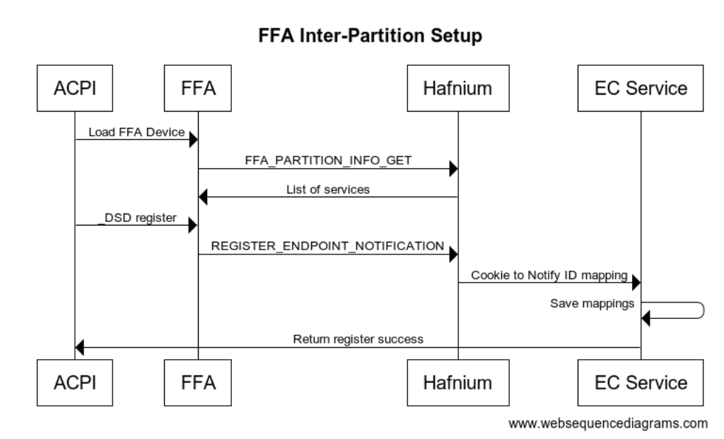
In the above example we indicate that the OS will handle 2 different notification events for UUID 330c1273-fde5-4757-9819-5b6539037502 which is our EC management UUID. FFA knows which secure partition this maps to based on the list of services for each SP it has retrieved. Rather than having to keep track of all the physical bits in the bitmask that are used the FFA driver keeps track of this and allows each service to create a list of virtual ID’s they need to handle. The FFA driver then maps this to one of the available bits in the hardware bitmask and passes this mapping down to the notification service running in a given SP.
Please refer to ARM documentation for full details on Inter-partition protocol DEN0077A_Firmware_Framework_Arm_A-profile_1.3
Input
| Parameter | Register | Value |
|---|---|---|
| FFA_MSG_SEND_DIRECT_REQ2 | X0 | 0xC400008D |
| Sender/Receiver Id | X1 | Bits[31:16]: Sender endpoint ID Bits[15:0]: Receiver endpoint ID |
| Protocol UUID low | X2 | Bytes[0..7] of Inter-partition setup protocol UUID |
| Protocol UUID high | X3 | Bytes[8..15] of Inter-partition setup protocol UUID |
| Reserved SBZ | X4 | 0x0 |
| Sender UUID low | X5 | Bytes[0..7] of service UUID |
| Sender UUID high | X6 | Bytes[8..15] of service UUID |
| Receiver UUID low | X7 | Bytes[0..7] of service UUID |
| Receiver UUID high | X8 | Bytes[8..15] of service UUID |
| Message Information | X9 | Bits[63:9]: Reserved MBZ Bit[8]: Message Direction - b’0 Request Message Bits[7:3]: Reserved MBZ Bits[2:0]: Message ID - b’010: Notification registration for a service |
| Cookie Information | X10 | Bits[63:9]: Bits[63:9]: Reserved MBZ Bits[8:0]: Count of (cookie,notification ID) tuples - 1 <= Count <= 7 |
| Tuple Mapping | X11-xX17 | Bits[63:32]: Cookie value Bits[31:23]: Notification ID associated with cookie Bits[22:1]: Reserved MBZ Bit[0]: Per-vcpu notification flag - b’0: Notification is a global notification - b’1: Notification is per-vcpu notification |
Output
| Parameter | Register | Value |
|---|---|---|
| FFA_MSG_SEND_DIRECT_RESP2 | X0 | 0xC400008E |
| Sender/Receiver Id | X1 | Bits[31:16]: Sender endpoint ID Bits[15:0]: Receiver endpoint ID |
| Protocol UUID low | X2 | Bytes[0..7] of Inter-partition setup protocol UUID |
| Protocol UUID high | X3 | Bytes[8..15] of Inter-partition setup protocol UUID |
| Reserved SBZ | X4 | 0x0 |
| Sender UUID low | X5 | Bytes[0..7] of service UUID |
| Sender UUID high | X6 | Bytes[8..15] of service UUID |
| Receiver UUID low | X7 | Bytes[0..7] of service UUID |
| Receiver UUID high | X8 | Bytes[8..15] of service UUID |
| Message Information | X9 | Bits[63:9]: Reserved MBZ Bit[8]: Message Direction - b’1 Response Message Bits[7:3]: Reserved MBZ Bits[2:0]: Message ID - b’010: Notification registration for a service |
| Cookie Information | X10 | Bits[63:9]: Bits[63:9]: Reserved MBZ Bits[8:0]: Count of (cookie,notification ID) tuples - 1 <= Count <= 7 |
| Tuple Mapping | X11-xX17 | Bits[63:32]: Cookie value Bits[31:23]: Notification ID associated with cookie Bits[22:1]: Reserved MBZ Bit[0]: Per-vcpu notification flag - b’0: Notification is a global notification - b’1: Notification is per-vcpu notification |
Note this NOTIFICATION_REGISTER request is sent to the Inter-Partition Service UUID in the SP. The UUID of the service that the notifications are for are stored in X5/X6 registers shown above.
The UUID for notification service is {e474d87e-5731-4044-a727-cb3e8cf3c8df} which is stored in X2/X3.
Notification Events
All notification events sent from all secure partitions are passed back through the FFA driver. The notification calls the _DSM method. Function 0 is always a bitmap of all the other functions supported. We must support at least Query and Notify. The UUID is stored in Arg0 and the notification cookie is stored in Arg3 when Arg2 is 11.
Method(_DSM, 0x4, NotSerialized)
{
// Arg0 - UUID 0194daab-ab08-7d5e-aea3-854bc457606a
// Arg1 - Revision
// Arg2: Function Index
// 0 - Query
// 1 - Notify
// 2 - binding failure
// 3 - infra failure
// Arg3 - Data
//
// Device specific method used to query
// configuration data. See ACPI 5.0 specification
// for further details.
//
If(LEqual(Arg0, Buffer(0x10) {
//
// UUID: {0194daab-ab08-7d5e-aea3-854bc457606a}
//
0x01, 0x94, 0xda, 0xab, 0xab, 0x08, 0x7d, 0x5e, 0xae, 0xa3, 0x85, 0x4b, 0xc4, 0x57, 0x60, 0x6a
}))
{
// Query Function
If(LEqual(Arg2, 0x0))
{
Return(Buffer(One) { 0x0f }) // Bitmask Query + Notify + binding failure + infra failure
}
// Notify Function
If(LEqual(Arg2, 0x1))
{
// Arg3 - Package {UUID, Cookie}
Store(DeRefOf(Index(Arg3,1)), \_SB.ECT0.NEVT )
}
// Binding Failure
If(LEqual(Arg2, 0x2))
{
// Arg3 Binding failure details
}
// Infra Failure
If(LEqual(Arg2, 0x3))
{
// Arg3 Infra failure details
}
}
Return(Buffer(One) { 0x00 })
}
The following is the call flow showing a secure interrupt arriving to the EC service which results in a notification back to ACPI. The notification payload can optionally be written to a shared buffer or ACPI can make another call back into EC service to retrieve the notification details.
In the _DSM, Arg2=1, Arg3 only contains the ID of the notification and no other payload, so both ACPI and the EC service must be designed either with shared memory buffer or a further notify data packet.
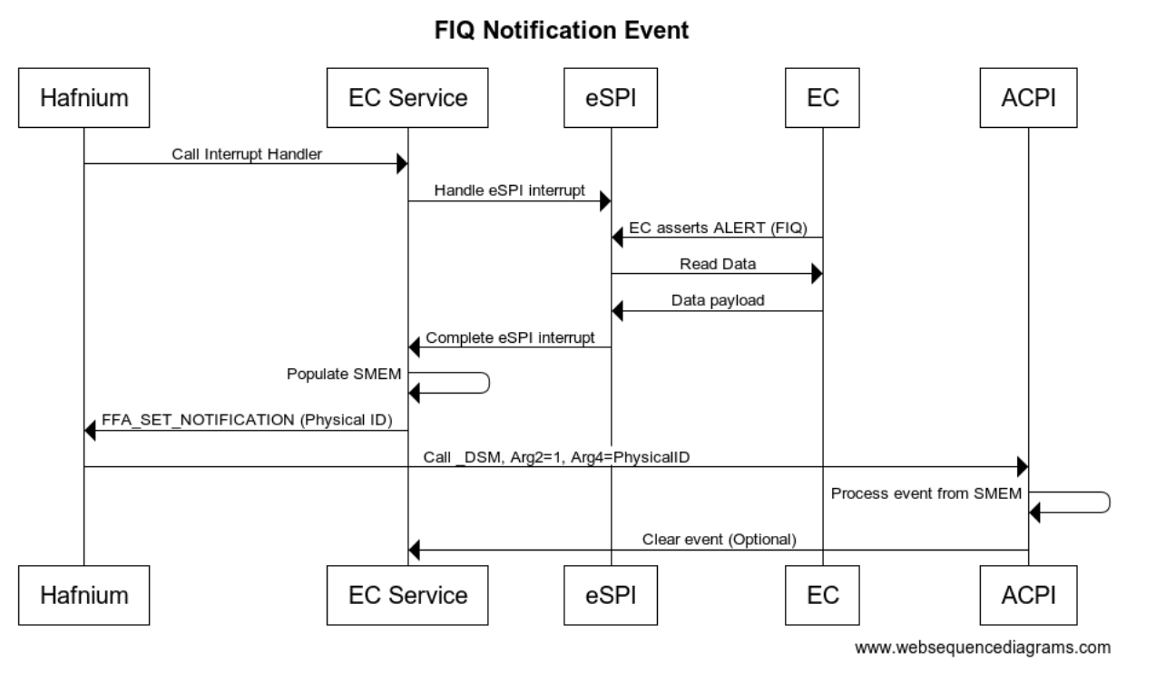
Runtime Requests
During runtime the non-secure side uses FFA_MSG_SEND_DIRECT_REQ2 requests to send requests to a given service within an SP. Any request that is expected to take longer than 1 ms should yield control back to the OS by calling FFA_YIELD within the service. When FFA_YIELD is called it will return control back to the OS to continue executing but the corresponding ACPI thread will be blocked until the original FFA request completes with DIRECT_RSP2. Note this creates a polling type interface where the OS will resume the SP thread after the timeout specified. The following is sample call sequence.
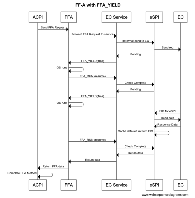
FFA Example Data Flow
For an example let’s take the battery status request _BST and follow data through.
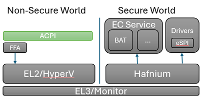
FFA_REQ_PACKET req = {
0x0, // Initialize to no error
0x0, // Let the OS populate the sender/receiver ID
{0x25,0xcb,0x52,0x07,0xac,0x36,0x42,0x7d,0xaa,0xef,0x3a,0xa7,0x88,0x77,0xd2,0x7e},
0x2 // EC_BAT_GET_BST
}
The equivalent to write this data into a BUFF in ACPI is as follows
CreateDwordField(BUFF,0,STAT) // Out – Status for req/rsp
CreateField(BUFF,64,64,RECV) // In/Out – Sender/Receiver ID
CreateField(BUFF,128,128,UUID) // UUID of service
CreateField(BUFF,256,8,CMDD) // In – First byte of command
CreateField(BUFF,256,128,BSTD) // Out – Raw data response 4 DWords
Store(0x2, CMDD)
Store(ToUUID ("25cb5207-ac36-427d-aaef-3aa78877d27e"), UUID)
Store(Store(BUFF, \\_SB_.FFA0.FFAC), BUFF)
The ACPI interpreter when walking through this code creates a buffer and populates the data into buffer. The last line indicates to send this buffer over FFA interface.
ACPI calls into the FFA interface to send the data over to the secure world EC Service
typedef struct _FFA_INTERFACE {
ULONG Version;
PFFA_MSG_SEND_DIRECT_REQ2 SendDirectReq2;
} FFA_INTERFACE, PFFA_INTERFACE;
FFA Parsing
FFA is in charge of sending the SMC over to the secure world and routing to the correct service based on UUID.
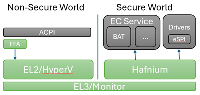
X0 = SEND_DIRECT_REQ2 SMC command ID
X1 = Source ID and Destination ID
X2 = UUID Low
X3 = UUID High
X4-X17 = rawdata
Note: The status and length are not passed through to the secure world they are consumed only be ACPI.
HyperV and Monitor have a chance to filter or deny the request, but in general just pass the SMC request through to Hafnium
Hafnium extracts the data from the registers into an sp_msg structure which is directly mapping contents from x0-x17 into these fields.
pub struct FfaParams {
pub x0: u64,
pub x1: u64,
pub x2: u64,
pub x3: u64,
pub x4: u64,
pub x5: u64,
pub x6: u64,
pub x7: u64,
pub x8: u64,
pub x9: u64,
pub x10: u64,
pub x11: u64,
pub x12: u64,
pub x13: u64,
pub x14: u64,
pub x15: u64,
pub x16: u64,
pub x17: u64,
}
The EC service receives all direct messages through the odp-ffa crate in DirectMessage. You will find this conversion into the RegisterPayload here.
fn try_from(value: SmcParams) -> Result<Self, Self::Error> {
let source_id = (value.x1 & 0xFFFF) as u16;
let destination_id = (value.x1 >> 16) as u16;
let uuid_high = u64::from_be(value.x2);
let uuid_low = u64::from_be(value.x3);
let uuid = Uuid::from_u64_pair(uuid_high, uuid_low);
// x4-x17 are for payload (14 registers)
let payload_regs = [
value.x4, value.x5, value.x6, value.x7, value.x8, value.x9, value.x10, value.x11, value.x12, value.x13,
value.x14, value.x15, value.x16, value.x17,
];
let payload_bytes_iter = payload_regs.iter().flat_map(|®| u64::to_le_bytes(reg).into_iter());
let payload = RegisterPayload::from_iter(payload_bytes_iter);
Ok(DirectMessage {
source_id,
destination_id,
uuid,
payload,
})
}
The destination_id is used to route the message to the correct SP, this is based on the ID field in the DTS description file. Eg: id = <0x8001>;
Embassy and Scheduling
The Secure Partition uses embassy as the scheduler for secure partition. This allows us to use await and do useful work while waiting for events even when we only are single threaded.
Embassy depeneds on timers and interrupts for signalling events. When we don’t have any work to do we still in the poll loop today. Optimizations can be made to yield control back to non-secure world in these situations.
EC Service Parsing
Within the EC partition there are several services that register their UUID to receive messages. You will find the main message loop and registration of each service in the embassy_main entry.
service_list![
ec_service_lib::services::Thermal::new(),
ec_service_lib::services::Battery::new(),
ec_service_lib::services::FwMgmt::new(),
ec_service_lib::services::Notify::new()
]
.run_message_loop()
.await
.expect("Error in run_message_loop");
Each service must implement the following 3 functions to register and allow it to recieve direct messages. The following is example implementation of the notification service entry.
const UUID: Uuid = uuid!("e474d87e-5731-4044-a727-cb3e8cf3c8df");
impl Service for Notify {
fn service_name(&self) -> &'static str {
"Notify"
}
fn service_uuid(&self) -> Uuid {
UUID
}
async fn ffa_msg_send_direct_req2(&mut self, msg: MsgSendDirectReq2) -> Result<MsgSendDirectResp2> {
let req: NotifyReq = msg.clone().into();
debug!("Received notify command: {:?}", req.msg_info.message_id());
let payload = match req.msg_info.message_id() {
MessageID::Setup => RegisterPayload::from(self.nfy_setup(req)),
MessageID::Destroy => RegisterPayload::from(self.nfy_destroy(req)),
_ => {
error!("Unknown Notify Command: {:?}", req.msg_info.message_id());
return Err(odp_ffa::Error::Other("Unknown Notify Command"));
}
};
Ok(MsgSendDirectResp2::from_req_with_payload(&msg, payload))
}
}
Large Data Transfers
When making an FFA_MSG_SEND_DIRECT_REQ2 call the data is stored in registers X0-X17. X0-X3 are reserved to store the Function Id, Source Id, Destination Id and UUID. This leaves X4-X17 or 112 bytes. For larger messages they either need to be broken into multiple pieces or make use of a shared buffer between the OS and Secure Partition.
Shared Buffer Definitions
To create a shared buffer you need to modify the dts file for the secure partition to include mapping to your buffer.
ns_comm_buffer {
description = "ns-comm";
base-address = <0x00000100 0x60000000>;
pages-count = <0x8>;
attributes = <NON_SECURE_RW>;
};
During UEFI Platform initialization you will need to do the following steps, see the FFA specification for more details on these commands
- FFA_MAP_RXTX_BUFFER
- FFA_MEM_SHARE
- FFA_MSG_SEND_DIRECT_REQ2 (EC_CAP_MEM_SHARE)
- FFA_UNMAP_RXTX_BUFFER
The RXTX buffer is used during larger packet transfers but can be overridden and updated by the framework. The MEM_SHARE command uses the RXTX buffer so we first map that buffer then populate our memory descriptor requests to the TX_BUFFER and send to Hafnium. After sending the MEM_SHARE request we need to instruct our SP to retrieve this memory mapping request. This is done through our customer EC_CAP_MEM_SHARE request where we describe the shared memory region that UEFI has donated. From there we call FFA_MEM_RETRIEVE_REQ to map the shared memory that was described to Hafnium. After we are done with the RXTX buffers we must unmap them as the OS will re-map new RXTX buffers. From this point on both Non-secure and Secure side will have access to this shared memory buffer that was allocated.
Async Transfers
All services are single threaded by default. Even when doing FFA_YIELD it does not allow any new content to be executed within the service. If you need your service to be truly asynchronous you must have commands with delayed responses.
There is no packet identifier by default and tracking of requests and completion by FFA, so the sample solution given here is based on shared buffers defined in previous section and existing ACPI and FFA functionality.
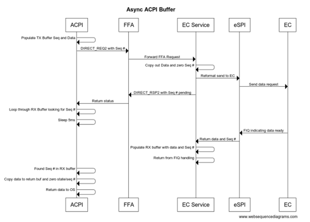
Inside of our FFA functions rather than copying our data payload into the direct registers we define a queue in shared memory and populate the actual data into this queue entry. In the FFA_MSG_SEND_DIRECT_REQ2 we populate an ASYNC command ID (0x0) along with the seq #. The seq # is then used by the service to locate the request in the TX queue. We define a separate queue for RX and TX so we don’t need to synchronize between OS and secure partition.
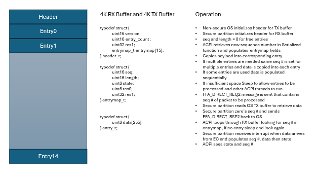
ACPI Structures and Methods for Asynchronous
The SMTX is shared memory TX region definition
// Shared memory regions and ASYNC implementation
OperationRegion (SMTX, SystemMemory, 0x10060000000, 0x1000)
// Store our actual request to shared memory TX buffer
Field (SMTX, AnyAcc, NoLock, Preserve)
{
TVER, 16,
TCNT, 16,
TRS0, 32,
TB0, 64,
TB1, 64,
TB2, 64,
TB3, 64,
TB4, 64,
TB5, 64,
TB6, 64,
TB7, 64,
Offset(0x100), // First Entry starts at 256 byte offset each entry is 256 bytes
TE0, 2048,
TE1, 2048,
TE2, 2048,
TE3, 2048,
TE4, 2048,
TE5, 2048,
TE6, 2048,
TE7, 2048,
}
The QTXB method copies data into first available entry in the TX queue and returns sequence number used.
// Arg0 is buffer pointer
// Arg1 is length of Data
// Return Seq \#
Method(QTXB, 0x2, Serialized) {
Name(TBX, 0x0)
Store(Add(ShiftLeft(1,32),Add(ShiftLeft(Arg1,16),SEQN)),TBX)
Increment(SEQN)
// Loop until we find a free entry to populate
While(One) {
If(LEqual(And(TB0,0xFFFF),0x0)) {
Store(TBX,TB0); Store(Arg0,TE0); Return( And(TBX,0xFFFF) )
}
If(LEqual(And(TB1,0xFFFF),0x0)) {
Store(TBX,TB1); Store(Arg0,TE1); Return( And(TBX,0xFFFF) )
}
If(LEqual(And(TB2,0xFFFF),0x0)) {
Store(TBX,TB2); Store(Arg0,TE2); Return( And(TBX,0xFFFF) )
}
If(LEqual(And(TB3,0xFFFF),0x0)) {
Store(TBX,TB3); Store(Arg0,TE3); Return( And(TBX,0xFFFF) )
}
If(LEqual(And(TB4,0xFFFF),0x0)) {
Store(TBX,TB4); Store(Arg0,TE4); Return( And(TBX,0xFFFF) )
}
If(LEqual(And(TB5,0xFFFF),0x0)) {
Store(TBX,TB5); Store(Arg0,TE5); Return( And(TBX,0xFFFF) )
}
If(LEqual(And(TB6,0xFFFF),0x0)) {
Store(TBX,TB6); Store(Arg0,TE6); Return( And(TBX,0xFFFF) )
}
If(LEqual(And(TB7,0xFFFF),0x0)) {
Store(TBX,TB7); Store(Arg0,TE7); Return( And(TBX,0xFFFF) )
}
Sleep(5)
}
}
The SMRX is shared memory region for RX queues
// Shared memory region
OperationRegion (SMRX, SystemMemory, 0x10060001000, 0x1000)
// Store our actual request to shared memory TX buffer
Field (SMRX, AnyAcc, NoLock, Preserve)
{
RVER, 16,
RCNT, 16,
RRS0, 32,
RB0, 64,
RB1, 64,
RB2, 64,
RB3, 64,
RB4, 64,
RB5, 64,
RB6, 64,
RB7, 64,
Offset(0x100), // First Entry starts at 256 byte offset each entry is 256 bytes
RE0, 2048,
RE1, 2048,
RE2, 2048,
RE3, 2048,
RE4, 2048,
RE5, 2048,
RE6, 2048,
RE7, 2048,
}
The RXDB function takes sequence number as input and will keep looping through all the entries until we see packet has completed. Sleeps for 5ms between each iteration to allow the OS to do other things and other ACPI threads can run.
// Allow multiple threads to wait for their SEQ packet at once
// If supporting packet \> 256 bytes need to modify to stitch together packet
Method(RXDB, 0x1, Serialized) {
Name(BUFF, Buffer(256){})
// Loop forever until we find our seq
While (One) {
If(LEqual(And(RB0,0xFFFF),Arg0)) {
CreateField(BUFF, 0, Multiply(And(ShiftRight(RB0,16),0xFFFF),8), XB0)
Store(RE0,BUFF); Store(0,RB0); Return( XB0 )
}
If(LEqual(And(RB1,0xFFFF),Arg0)) {
CreateField(BUFF, 0, Multiply(And(ShiftRight(RB1,16),0xFFFF),8), XB1)
Store(RE1,BUFF); Store(0,RB1); Return( XB1 )
}
If(LEqual(And(RB2,0xFFFF),Arg0)) {
CreateField(BUFF, 0, Multiply(And(ShiftRight(RB2,16),0xFFFF),8), XB2)
Store(RE2,BUFF); Store(0,RB2); Return( XB2 )
}
If(LEqual(And(RB3,0xFFFF),Arg0)) {
CreateField(BUFF, 0, Multiply(And(ShiftRight(RB3,16),0xFFFF),8), XB3)
Store(RE3,BUFF); Store(0,RB3); Return( XB3 )
}
If(LEqual(And(RB4,0xFFFF),Arg0)) {
CreateField(BUFF, 0, Multiply(And(ShiftRight(RB4,16),0xFFFF),8), XB4)
Store(RE4,BUFF); Store(0,RB4); Return( XB4 )
}
If(LEqual(And(RB5,0xFFFF),Arg0)) {
CreateField(BUFF, 0, Multiply(And(ShiftRight(RB5,16),0xFFFF),8), XB5)
Store(RE5,BUFF); Store(0,RB5); Return( XB5 )
}
If(LEqual(And(RB6,0xFFFF),Arg0)) {
CreateField(BUFF, 0, Multiply(And(ShiftRight(RB6,16),0xFFFF),8), XB6)
Store(RE6,BUFF); Store(0,RB6); Return( XB6 )
}
If(LEqual(And(RB7,0xFFFF),Arg0)) {
CreateField(BUFF, 0, Multiply(And(ShiftRight(RB7,16),0xFFFF),8), XB7)
Store(RE7,BUFF); Store(0,RB7); Return( XB7 )
}
Sleep(5)
}
// If we get here didn't find a matching sequence number
Return (Ones)
}
The following is sample code to transmit a ASYNC request and wait for the data in the RX buffer.
Method(ASYC, 0x0, Serialized) {
If(LEqual(\\_SB.FFA0.AVAL,One)) {
CreateDwordField(BUFF,0,STAT) // Out – Status for req/rsp
CreateField(BUFF,128,128,UUID) // UUID of service
CreateByteField(BUFF,32,CMDD) // Command register
CreateWordField(BUFF,33,BSQN) // Sequence Number
Store(0x0, CMDD) // EC_ASYNC command
Local0 = QTXB(BUFF,20) // Copy data to our queue entry and get back SEQN
Store(Local0,BSQN) // Sequence packet to read from shared memory
Store(ToUUID("330c1273-fde5-4757-9819-5b6539037502"), UUID)
Store(Store(BUFF, \\_SB_.FFA0.FFAC), BUFF)
If(LEqual(STAT,0x0) ) // Check FF-A successful?
{
Return (RXDB(Local0)) // Loop through our RX queue till packet completes
}
}
Recovery and Errors
The eSPI or bus driver is expected to detect if the EC is not responding and retry. The FFA driver will report back in the status byte if it cannot successfully talk to the secure world. If there are other failures generally they should be returned back up through ACPI with a value of (Ones) to indicate failure condition. This may cause some features to work incorrectly.
It is also expected that the EC has a watchdog if something on the EC is hung it should reset and reload on its own. The EC is also responsible for monitoring that the system is running within safe parameters. The thermal requests and queries are meant to be advisory in nature and EC should be able to run independently and safely without any intervention from the OS.
EC Firmware Management
This service is to provide details about the security state, supported features, debug, firmware version and firmware update functionality.
NIST SP 800-193 compliance requires failsafe update of primary and backup EC FW images. EC should run from primary partition while writing backup partitions and then change flag to indicate backup becomes primary and primary becomes backup.
| Capability Command | Description |
|---|---|
| EC_CAP_GET_FW_STATE = 0x1 | Return details of FW in EC, DICE, Secure Boot, Version, etc |
| EC_CAP_GET_SVC_LIST = 0x2 | Get list of services/features that this EC supports |
| EC_CAP_GET_BID = 0x3 | Read Board ID that is used customized behavior |
| EC_CAP_TEST_NFY = 0x4 | Create test notification event |
Get Firmware State
Returns start of the overall EC if DICE and secure boot was enabled, currently running firmware version, EC status like boot failures.
Secure Boot and DICE
DICE is a specification from the Trusted Computing Group that allows the MCU to verify the signature of the code that it is executing, thereby establishing trust in the code. To do this, it has a primary bootloader program that reads the firmware on flash and using a key that is only accessible by the ROM bootloader, can verify the authenticity of the firmware.
Trusted Platform Architecture - Device Identity Composition Engine (trustedcomputinggroup.org)
Input Parameters
None
Output Parameters
| Field | Bits | Description |
|---|---|---|
| FWVersion | 16 | Version of FW running on EC |
| SecureState | 8 |
Bit mask representing the secure state of the device 0 – DICE is enabled 1 – Firmware is signed |
| BootStatus | 8 |
Boot status and error codes 0 = SUCCESS |
FFA ACPI Example
Method (TFWS) {
// Check to make sure FFA is available and not unloaded
If(LEqual(\\_SB.FFA0.AVAL,One)) {
CreateQwordField(BUFF,0,STAT) // Out – Status for req/rsp
CreateField(BUFF,128,128,UUID) // UUID of service
CreateByteField(BUFF,32, CMDD) // In – First byte of command
CreateDwordField(BUFF,32,FWSD) // Out – Raw data response (overlaps with CMDD)
Store(ToUUID("330c1273-fde5-4757-9819-5b6539037502"), UUID) // Management
Store(0x1, CMDD) // EC_CAP_GET_FW_STATE
Store(Store(BUFF, \_SB_.FFA0.FFAC), BUFF)
If(LEqual(STAT,0x0) ) // Check FF-A successful?
{
Return (FWSD)
}
}
Return(Zero)
}
Get Features Supported
Get a list of services/features supported by this EC. Several features like HID devices are optional and may not be present. OEM services may also be added to this list as additional features supported.
Input Parameters
None
Output Parameters
| Field | Bits | Description |
|---|---|---|
| DebugMask | 16 | 0 - Supports reset reason 1 - Supports debug tracing |
| BatteryMask | 8 | 0 - Battery 0 present 1 - Battery 1 present … |
| FanMask | 8 | 0 - Fan 0 present 1 - Fan 1 present … |
| ThermalMask | 8 | 0 - Skin TZ present |
| HIDMask | 8 | 0 - HID0 present 1 - HID1 present … |
| KeyMask | 16 | 0 - Power key present 1 - LID switch present 2 - VolUp key present 3 - VolDown key present 4 - Camera key present |
FFA ACPI Example
Method(TFET, 0x0, Serialized) {
If(LEqual(\\_SB.FFA0.AVAL,One)) {
CreateQwordField(BUFF,0,STAT) // Out – Status for req/rsp
CreateField(BUFF,128,128,UUID) // UUID of service
CreateByteField(BUFF,32, CMDD) // In – First byte of command
CreateWordField(BUFF,32,FET0) // DebugMask
CreateByteField(BUFF,34,FET1) // BatteryMask
CreateByteField(BUFF,35,FET2) // FanMask
CreateByteField(BUFF,36,FET3) // ThermalMask
CreateByteField(BUFF,37,FET4) // HIDMask
CreateWordField(BUFF,38,FET5) // KeyMask
Store(0x2, CMDD) // EC_CAP_GET_SVC_LIST
Store(ToUUID("330c1273-fde5-4757-9819-5b6539037502"), UUID)
Store(Store(BUFF, \\_SB_.FFA0.FFAC), BUFF)
If(LEqual(STAT,0x0) ) {
Return (package () {FET0,FET1,FET2,FET3,FET4,FET5})
}
}
Return(package () {0,0,0,0,0,0,0})
}
Get Board ID
EC is often used to read pins or details to determine the HW configuration based on GPIO’s or ADC values. This ID allows SW to change behavior depending on this HW version information.
Input Parameters
None
Output Parameters
| Field | Bits | Description |
|---|---|---|
| BoardID | 64 | Vendor defined |
FFA ACPI Example
Method(TBID, 0x0, Serialized) {
If(LEqual(\\_SB.FFA0.AVAL,One)) {
CreateQwordField(BUFF,0,STAT) // Out – Status for req/rsp
CreateField(BUFF,128,128,UUID) // UUID of service
CreateByteField(BUFF,32, CMDD) // In – First byte of command
CreateDwordField(BUFF,32,BIDD) // Output Data
Store(0x3, CMDD) // EC_CAP_GET_BID
Store(ToUUID("330c1273-fde5-4757-9819-5b6539037502"), UUID)
Store(Store(BUFF, \\_SB_.FFA0.FFAC), BUFF)
If(LEqual(STAT,0x0) ) {
Return (BIDD)
} else {
}
Return(Zero)
}
Firmware Update
This should initiate update of a particular firmware in the backup partition to provide NIST SP 800-193 failsafe compliance. EC firmware update is planned to be handled through CFU. Further details are available in CFU specification.
EC Power Service
System Power State
OS calls in to notify EC or a change in system power state.
Perform appropriate power sequencing for the SoC from low power states (S3, S4, S5) to S0, and from S0 to low power states
Battery Service
Battery control is monitored through the Modern Power Thermal Framework (MPTF). See this specification for further details on implementing firmware for these features. This section outlines the interface required in ACPI for this framework to function.
Note: There is an issue with ACPI and embedded packages return Package() {BST0,BST1,BST2,BST3} returns “BST0”,“BST1”,“BST2”,“BST3” rather than the values pointed to by these variables. As such we need to create a global Name for BSTD and initialize default values and update these fields like the following.
Name (BSTD, Package (4) {
0x2,
0x500,
0x10000,
0x3C28
})
...
BSTD[0] = BST0
BSTD[1] = BST1
BSTD[2] = BST2
BSTD[3] = BST3
Return(BSTD)
| Command | Description |
|---|---|
| EC_BAT_GET_BIX = 0x1 | Returns information about battery, model, serial number voltage. Note this is a superset of BIF. (MPTF) |
| EC_BAT_GET_BST = 0x2 | Get Battery Status, must also have notify event on state change. (MPTF) |
| EC_BAT_GET_PSR = 0x3 | Returns whether this power source device is currently online. (MPTF) |
| EC_BAT_GET_PIF = 0x4 | Returns static information about a power source. (MPTF) |
| EC_BAT_GET_BPS = 0x5 | Power delivery capabilities of battery at present time. (MPTF) |
| EC_BAT_SET_BTP = 0x6 | Set battery trip point to generate SCI event (MPTF) |
| EC_BAT_SET_BPT = 0x7 | Set Battery Power Threshold (MPTF) |
| EC_BAT_GET_BPC = 0x8 | Returns static variables that are associated with system power characteristics on the battery path and power threshold support settings. (MPTF) |
| EC_BAT_SET_BMC= 0x9 | Battery Maintenance Control |
| EC_BAT_GET_BMD = 0xA | Returns battery information regarding charging and calibration |
| EC_BAT_GET_BCT = 0xB | Returns battery charge time. |
| EC_BAT_GET_BTM = 0xC | Get estimated runtime of battery while discharging |
| EC_BAT_SET_BMS = 0xD | Sets battery capacity sampling time in ms |
| EC_BAT_SET_BMA = 0xE | Battery Measurement Average Interval |
| EC_BAT_GET_STA = 0xF | Get battery availability |
EC_BAT_GET_BIX
Returns information about battery, model, serial number voltage etc
Input Parameters
None
Output Parameters
Should return structure as defined by ACPI specification
10. Power Source and Power Meter Devices — ACPI Specification 6.4 documentation
FFA ACPI Example
Name (BIXD, Package(21) {
0,
0,
0x15F90,
0x15F90,
1,
0x3C28,
0x8F,
0xE10,
1,
0x17318,
0x03E8,
0x03E8,
0x03E8,
0x03E8,
0x380,
0xE1,
" ",
" ",
" ",
" ",
0
})
Method (_BIX, 0, Serialized) {
// Check to make sure FFA is available and not unloaded
If(LEqual(\_SB.FFA0.AVAL,One)) {
CreateDwordField(BUFF,0,STAT) // Out – Status for req/rsp
CreateField(BUFF,128,128,UUID) // UUID of service
CreateByteField(BUFF,32,CMDD) // In – First byte of command
CreateDwordField(BUFF,32,BIX0) // Out – Revision
CreateDwordField(BUFF,36,BIX1) // Out – Power Unit
CreateDwordField(BUFF,40,BIX2) // Out – Design Capacity
CreateDwordField(BUFF,44,BIX3) // Out – Last Full Charge Capacity
CreateDwordField(BUFF,48,BIX4) // Out – Battery Technology
CreateDwordField(BUFF,52,BIX5) // Out – Design Voltage
CreateDwordField(BUFF,56,BIX6) // Out – Design Capacity of Warning
CreateDwordField(BUFF,60,BIX7) // Out – Design Capacity of Low
CreateDwordField(BUFF,64,BIX8) // Out – Cycle Count
CreateDwordField(BUFF,68,BIX9) // Out – Measurement Accuracy
CreateDwordField(BUFF,72,BI10) // Out – Max Sampling Time
CreateDwordField(BUFF,76,BI11) // Out – Min Sampling Time
CreateDwordField(BUFF,80,BI12) // Out – Max Averaging Internal
CreateDwordField(BUFF,84,BI13) // Out – Min Averaging Interval
CreateDwordField(BUFF,88,BI14) // Out – Battery Capacity Granularity 1
CreateDwordField(BUFF,92,BI15) // Out – Battery Capacity Granularity 2
CreateField(BUFF,768,64,BI16) // Out – Model Number
CreateField(BUFF,832,64,BI17) // Out – Serial number
CreateField(BUFF,896,64,BI18) // Out – Battery Type
CreateField(BUFF,960,64,BI19) // Out – OEM Information
CreateDwordField(BUFF,128,BI20) // Out – OEM Information
Store(0x1, CMDD) //EC_BAT_GET_BIX
Store(ToUUID("25cb5207-ac36-427d-aaef-3aa78877d27e"), UUID)
Store(Store(BUFF, \_SB_.FFA0.FFAC), BUFF)
If(LEqual(STAT,0x0) ) // Check FF-A successful?
{
BIXD[0] = BIX0
BIXD[1] = BIX1
BIXD[2] = BIX2
BIXD[3] = BIX3
BIXD[4] = BIX4
BIXD[5] = BIX5
BIXD[6] = BIX6
BIXD[7] = BIX7
BIXD[8] = BIX8
BIXD[9] = BIX9
BIXD[10] = BI10
BIXD[11] = BI11
BIXD[12] = BI12
BIXD[13] = BI13
BIXD[14] = BI14
BIXD[15] = BI15
BIXD[16] = BI16
BIXD[17] = BI17
BIXD[18] = BI18
BIXD[19] = BI19
BIXD[20] = BI20
}
}
Return(BIXD)
}
EC_BAT_GET_BST
This object returns the present battery status. Whenever the Battery State value changes, the system will generate an SCI to notify the OS.
Input Parameters
None
Output Parameters
Should return structure as defined by ACPI specification
10. Power Source and Power Meter Devices — ACPI Specification 6.4 documentation
FFA ACPI Example
Name (BSTD, Package (4) {
0x2,
0x500,
0x10000,
0x3C28
})
Method (_BST, 0, Serialized) {
// Check to make sure FFA is available and not unloaded
If(LEqual(\_SB.FFA0.AVAL,One)) {
CreateDwordField(BUFF,0,STAT) // Out – Status for req/rsp
CreateField(BUFF,128,128,UUID) // UUID of service
CreateByteField(BUFF,32,CMDD) // In – First byte of command
CreateDwordField(BUFF,32,BST0) // Out – Battery State DWord
CreateDwordField(BUFF,36,BST1) // Out – Battery Rate DWord
CreateDwordField(BUFF,40,BST2) // Out – Battery Reamining Capacity DWord
CreateDwordField(BUFF,44,BST3) // Out – Battery Voltage DWord
Store(0x2, CMDD) //EC_BAT_GET_BST
Store(ToUUID("25cb5207-ac36-427d-aaef-3aa78877d27e"), UUID)
Store(Store(BUFF, \_SB_.FFA0.FFAC), BUFF)
If(LEqual(STAT,0x0) ) // Check FF-A successful?
{
BSTD[0] = BST0
BSTD[1] = BST1
BSTD[2] = BST2
BSTD[3] = BST3
}
}
Return(BSTD)
}
EC_BAT_GET_PSR
Returns whether the power source device is currently in use. This can be used to determine if system is running off this power supply or adapter. On mobile systes this will report that the system is not running on the AC adapter if any of the batteries in the system is being forced to discharge. In systems that contains multiple power sources, this object reports the power source’s online or offline status.
Input Parameters
None
Output Parameters
Should return structure as defined by ACPI specification
10. Power Source and Power Meter Devices — ACPI Specification 6.4 documentation
FFA ACPI Example
Method (_PSR, 0, Serialized) {
// Check to make sure FFA is available and not unloaded
If(LEqual(\_SB.FFA0.AVAL,One)) {
CreateDwordField(BUFF,0,STAT) // Out – Status for req/rsp
CreateField(BUFF,128,128,UUID) // UUID of service
CreateByteField(BUFF,32,CMDD) // In – First byte of command
CreateDwordField(BUFF,32,PSR0) // Out – Power Source
Store(0x3, CMDD) //EC_BAT_GET_PSR
Store(ToUUID("25cb5207-ac36-427d-aaef-3aa78877d27e"), UUID)
Store(Store(BUFF, \_SB_.FFA0.FFAC), BUFF)
If(LEqual(STAT,0x0) ) // Check FF-A successful?
{
return(PSR0)
}
}
Return(0)
}
EC_BAT_GET_PIF
This object returns information about the Power Source, which remains constant until the Power Source is changed. When the power source changes, the platform issues a Notify(0x0) (Bus Check) to the Power Source device to indicate that OSPM must re-evaluate the _PIF object.
Input Parameters
None
Output Parameters
Should return structure as defined by ACPI specification
10. Power Source and Power Meter Devices — ACPI Specification 6.4 documentation
FFA ACPI Example
Name( PIFD, Package(6) {
0, // Out – Power Source State
0, // Out – Maximum Output Power
0, // Out – Maximum Input Power
" ", // Out – Model Number
" ", // Out – Serial Number
" " // Out – OEM Information
})
Method (_PIF, 0, Serialized) {
// Check to make sure FFA is available and not unloaded
If(LEqual(\_SB.FFA0.AVAL,One)) {
CreateDwordField(BUFF,0,STAT) // Out – Status for req/rsp
CreateField(BUFF,128,128,UUID) // UUID of service
CreateByteField(BUFF,32,CMDD) // In – First byte of command
CreateDwordField(BUFF,32,PIF0) // Out – Power Source State
CreateDwordField(BUFF,36,PIF1) // Out – Maximum Output Power
CreateDwordField(BUFF,40,PIF2) // Out – Maximum Input Power
CreateField(BUFF,352,64,PIF3) // Out – Model Number
CreateField(BUFF,416,64,PIF4) // Out – Serial Number
CreateField(BUFF,480,64,PIF5) // Out – OEM Information
Store(0x4, CMDD) //EC_BAT_GET_PIF
Store(ToUUID("25cb5207-ac36-427d-aaef-3aa78877d27e"), UUID)
Store(Store(BUFF, \_SB_.FFA0.FFAC), BUFF)
If(LEqual(STAT,0x0) ) // Check FF-A successful?
{
PIFD[0] = PIF0
PIFD[1] = PIF1
PIFD[2] = PIF2
PIFD[3] = PIF3
PIFD[4] = PIF4
PIFD[5] = PIF5
}
}
Return(PIFD)
}
EC_BAT_GET_BPS
This optional object returns the power delivery capabilities of the battery at the present time. If multiple batteries are present within the system, the sum of peak power levels from each battery can be used to determine the total available power.
Input Parameters
None
Output Parameters
Should return structure as defined by ACPI specification
FFA ACPI Example
Name( BPSD, Package(5) {
0, // Out – Revision
0, // Out – Instantaneous Peak Power Level
0, // Out – Instantaneous Peak Power Period
0, // Out – Sustainable Peak Power Level
0 // Out – Sustainable Peak Power Period
})
Method (_BPS, 0, Serialized) {
// Check to make sure FFA is available and not unloaded
If(LEqual(\_SB.FFA0.AVAL,One)) {
CreateDwordField(BUFF,0,STAT) // Out – Status for req/rsp
CreateField(BUFF,128,128,UUID) // UUID of service
CreateByteField(BUFF,32,CMDD) // In – First byte of command
CreateDwordField(BUFF,32,BPS0) // Out – Revision
CreateDwordField(BUFF,36,BPS1) // Out – Instantaneous Peak Power Level
CreateDwordField(BUFF,40,BPS2) // Out – Instantaneous Peak Power Period
CreateDwordField(BUFF,44,BPS3) // Out – Sustainable Peak Power Level
CreateDwordField(BUFF,48,BPS4) // Out – Sustainable Peak Power Period
Store(0x5, CMDD) //EC_BAT_GET_BPS
Store(ToUUID("25cb5207-ac36-427d-aaef-3aa78877d27e"), UUID)
Store(Store(BUFF, \_SB_.FFA0.FFAC), BUFF)
If(LEqual(STAT,0x0) ) // Check FF-A successful?
{
BPSD[0] = BPS0
BPSD[1] = BPS1
BPSD[2] = BPS2
BPSD[3] = BPS3
BPSD[4] = BPS4
}
}
Return(BPSD)
}
EC_BAT_SET_BTP
This object is used to set a trip point to generate an SCI whenever the Battery Remaining Capacity reaches or crosses the value specified in the _BTP object. Required on systems supporting Modern Standby
Platform design for modern standby | Microsoft Learn
Input Parameters
See ACPI documentation for details
10. Power Source and Power Meter Devices — ACPI Specification 6.4 documentation
Output Parameters
None
FFA ACPI Example
Method (_BTP, 1, Serialized) {
// Check to make sure FFA is available and not unloaded
If(LEqual(\_SB.FFA0.AVAL,One)) {
CreateDwordField(BUFF,0,STAT) // Out – Status for req/rsp
CreateField(BUFF,128,128,UUID) // UUID of service
CreateByteField(BUFF,32,CMDD) // In – First byte of command
CreateDwordField(BUFF,36,BTP0) // In - Trip point value
Store(0x6, CMDD) //EC_BAT_SET_BTP
Store(Arg0, BTP0)
Store(ToUUID("25cb5207-ac36-427d-aaef-3aa78877d27e"), UUID)
Store(Store(BUFF, \_SB_.FFA0.FFAC), BUFF)
If(LEqual(STAT,0x0) ) // Check FF-A successful?
{
return(Zero )
}
}
Return(Zero)
}
EC_BAT_GET_BPC
This optional object returns static values that are used to configure power threshold support in the platform firmware. OSPM can use the information to determine the capabilities of power delivery and threshold support for each battery in the system.
Input Parameters
None
Output Parameters
Should return structure as defined by ACPI specification
10. Power Source and Power Meter Devices — ACPI Specification 6.4 documentation
FFA ACPI Example
Name( BPCD, Package(4) {
1, // Out - Revision
0, // Out - Threshold support
8000, // Out - Max Inst peak power
2000 // Out - Max Sust peak power
})
Method (_BPC, 0, Serialized) {
// Check to make sure FFA is available and not unloaded
If(LEqual(\_SB.FFA0.AVAL,One)) {
CreateDwordField(BUFF,0,STAT) // Out – Status for req/rsp
CreateField(BUFF,128,128,UUID) // UUID of service
CreateByteField(BUFF,32,CMDD) // In – First byte of command
CreateDwordField(BUFF,32,BPC0) // Out - Revision
CreateDwordField(BUFF,36,BPC1) // Out - Threshold support
CreateDwordField(BUFF,40,BPC2) // Out - Max Inst peak power
CreateDwordField(BUFF,44,BPC3) // Out - Max Sust peak power
Store(0x8, CMDD) //EC_BAT_GET_BPC
Store(ToUUID("25cb5207-ac36-427d-aaef-3aa78877d27e"), UUID)
Store(Store(BUFF, \_SB_.FFA0.FFAC), BUFF)
If(LEqual(STAT,0x0) ) // Check FF-A successful?
{
BPCD[0] = BPC0
BPCD[1] = BPC1
BPCD[2] = BPC2
BPCD[3] = BPC3
}
}
Return(BPCD)
}
EC_BAT_SET_BPT
his optional object may be present under a battery device. OSPM must read _BPC first to determine the power delivery capability threshold support in the platform firmware and invoke this Method in order to program the threshold accordingly. If the platform does not support battery peak power thresholds, this Method should not be included in the namespace.
Input Parameters
See ACPI specification for input parameters
10. Power Source and Power Meter Devices — ACPI Specification 6.4 documentation
Output Parameters
Should return structure as defined by ACPI specification
10. Power Source and Power Meter Devices — ACPI Specification 6.4 documentation
FFA ACPI Example
Method (_BPT, 3, Serialized) {
// Check to make sure FFA is available and not unloaded
If(LEqual(\_SB.FFA0.AVAL,One)) {
CreateDwordField(BUFF,0,STAT) // Out – Status for req/rsp
CreateField(BUFF,128,128,UUID) // UUID of service
CreateByteField(BUFF,32,CMDD) // In – First byte of command
CreateDwordField(BUFF,36,BPT0) // In - Revision
CreateDwordField(BUFF,40,BPT1) // In - Threshold ID
CreateDwordField(BUFF,44,BPT2) // In - Threshold value
CreateDwordField(BUFF,32,BPTS) // Out - Trip point value
Store(0x7, CMDD) //EC_BAT_SET_BPT
Store(Arg0, BPT0)
Store(Arg1, BPT1)
Store(Arg2, BPT2)
Store(ToUUID("25cb5207-ac36-427d-aaef-3aa78877d27e"), UUID)
Store(Store(BUFF, \_SB_.FFA0.FFAC), BUFF)
If(LEqual(STAT,0x0) ) // Check FF-A successful?
{
return(BPTS)
}
}
Return(Zero)
}
EC_BAT_SET_BMC
This object is used to initiate calibration cycles or to control the charger and whether or not a battery is powering the system. This object is only present under a battery device if the _BMD Capabilities Flags field has bit 0, 1, 2, or 5 set.
Input Parameters
See ACPI specification for input parameter definition
10. Power Source and Power Meter Devices — ACPI Specification 6.4 documentation
Output Parameters
None
FFA ACPI Example
Method (_BMC, 1, Serialized) {
// Check to make sure FFA is available and not unloaded
If(LEqual(\_SB.FFA0.AVAL,One)) {
CreateDwordField(BUFF,0,STAT) // Out – Status for req/rsp
CreateField(BUFF,128,128,UUID) // UUID of service
CreateByteField(BUFF,32,CMDD) // In – First byte of command
CreateDwordField(BUFF,36,BMC0) // In - Feature control flags
Store(0x9, CMDD) //EC_BAT_SET_BMC
Store(Arg0, BMC0)
Store(ToUUID("25cb5207-ac36-427d-aaef-3aa78877d27e"), UUID)
Store(Store(BUFF, \_SB_.FFA0.FFAC), BUFF)
}
Return(Zero)
}
EC_BAT_GET_BMD
This optional object returns information about the battery’s capabilities and current state in relation to battery calibration and charger control features. If the _BMC object (defined below) is present under a battery device, this object must also be present. Whenever the Status Flags value changes, AML code will issue a Notify(battery_device, 0x82). In addition, AML will issue a Notify(battery_device, 0x82) if evaluating _BMC did not result in causing the Status Flags to be set as indicated in that argument to _BMC. AML is not required to issue Notify(battery_device, 0x82) if the Status Flags change while evaluating _BMC unless the change does not correspond to the argument passed to _BMC.
10. Power Source and Power Meter Devices — ACPI Specification 6.4 documentation
Input Parameters
None
Output Parameters
Should return structure as defined by ACPI specification
FFA ACPI Example
Name( BMDD, Package(5) {
0, // Out - Status
0, // Out - Capability Flags
0, // Out - Recalibrate count
0, // Out - Quick recal time
0 // Out - Slow recal time
})
Method (_BMD, 0, Serialized) {
// Check to make sure FFA is available and not unloaded
If(LEqual(\_SB.FFA0.AVAL,One)) {
CreateDwordField(BUFF,0,STAT) // Out – Status for req/rsp
CreateField(BUFF,128,128,UUID) // UUID of service
CreateByteField(BUFF,32,CMDD) // In – First byte of command
CreateDwordField(BUFF,32,BMD0) // Out - Status
CreateDwordField(BUFF,36,BMD1) // Out - Capability Flags
CreateDwordField(BUFF,40,BMD2) // Out - Recalibrate count
CreateDwordField(BUFF,44,BMD3) // Out - Quick recal time
CreateDwordField(BUFF,48,BMD4) // Out - Slow recal time
Store(0xa, CMDD) //EC_BAT_GET_BMD
Store(ToUUID("25cb5207-ac36-427d-aaef-3aa78877d27e"), UUID)
Store(Store(BUFF, \_SB_.FFA0.FFAC), BUFF)
If(LEqual(STAT,0x0) ) // Check FF-A successful?
{
BMDD[0] = BMD0
BMDD[1] = BMD1
BMDD[2] = BMD2
BMDD[3] = BMD3
BMDD[4] = BMD4
}
}
Return(BMDD)
}
EC_BAT_GET_BCT
When the battery is charging, this optional object returns the estimated time from present to when it is charged to a given percentage of Last Full Charge Capacity.
10. Power Source and Power Meter Devices — ACPI Specification 6.4 documentation
Input Parameters
Input parameters as described in ACPI specification.
Output Parameters
Should return structure as defined by ACPI specification
FFA ACPI Example
Method (_BCT, 1, Serialized) {
// Check to make sure FFA is available and not unloaded
If(LEqual(\_SB.FFA0.AVAL,One)) {
CreateDwordField(BUFF,0,STAT) // Out – Status for req/rsp
CreateField(BUFF,128,128,UUID) // UUID of service
CreateByteField(BUFF,32,CMDD) // In – First byte of command
CreateDwordField(BUFF,36,BCT0) // In - ChargeLevel
CreateDwordField(BUFF,32,BCTD) // Out - Result
Store(0xb, CMDD) //EC_BAT_GET_BCT
Store(Arg0, BCT0)
Store(ToUUID("25cb5207-ac36-427d-aaef-3aa78877d27e"), UUID)
Store(Store(BUFF, \_SB_.FFA0.FFAC), BUFF)
If(LEqual(STAT,0x0) ) // Check FF-A successful?
{
return(BCTD)
}
}
Return(Zero)
}
EC_BAT_GET_BTM
This optional object returns the estimated runtime of the battery while it is discharging.
10. Power Source and Power Meter Devices — ACPI Specification 6.4 documentation
Input Parameters
Input parameters as described in ACPI specification.
Output Parameters
Should return structure as defined by ACPI specification
EC_BAT_SET_BMS
This object is used to set the sampling time of the battery capacity measurement, in milliseconds.
The Sampling Time is the duration between two consecutive measurements of the battery’s capacities specified in _BST, such as present rate and remaining capacity. If the OSPM makes two succeeding readings through _BST beyond the duration, two different results will be returned.
The OSPM may read the Max Sampling Time and Min Sampling Time with _BIX during boot time, and set a specific sampling time within the range with _BMS.
10. Power Source and Power Meter Devices — ACPI Specification 6.4 documentation
Input Parameters
Input parameters as described in ACPI specification.
Output Parameters
Should return structure as defined by ACPI specification
FFA ACPI Example
Method (_BMS, 1, Serialized) {
// Check to make sure FFA is available and not unloaded
If(LEqual(\_SB.FFA0.AVAL,One)) {
CreateDwordField(BUFF,0,STAT) // Out – Status for req/rsp
CreateField(BUFF,128,128,UUID) // UUID of service
CreateByteField(BUFF,32,CMDD) // In – First byte of command
CreateDwordField(BUFF,36,BMS0) // In - Sampling Time
CreateDwordField(BUFF,32,BMSD) // Out - Result code
Store(0xd, CMDD) //EC_BAT_SET_BMS
Store(Arg0, BMS0)
Store(ToUUID("25cb5207-ac36-427d-aaef-3aa78877d27e"), UUID)
Store(Store(BUFF, \_SB_.FFA0.FFAC), BUFF)
If(LEqual(STAT,0x0) ) // Check FF-A successful?
{
return(BMSD)
}
}
Return(Zero)
}
EC_BAT_SET_BMA
This object is used to set the averaging interval of the battery capacity measurement, in milliseconds. The Battery Measurement Averaging Interval is the length of time within which the battery averages the capacity measurements specified in _BST, such as remaining capacity and present rate.
The OSPM may read the Max Average Interval and Min Average Interval with _BIX during boot time, and set a specific average interval within the range with _BMA.
10. Power Source and Power Meter Devices — ACPI Specification 6.4 documentation
Input Parameters
Input parameters as described in ACPI specification.
Output Parameters
Should return structure as defined by ACPI specification
FFA ACPI Example
#![allow(unused)]
fn main() {
Method (_BMA, 1, Serialized) {
// Check to make sure FFA is available and not unloaded
If(LEqual(\_SB.FFA0.AVAL,One)) {
CreateDwordField(BUFF,0,STAT) // Out – Status for req/rsp
CreateField(BUFF,128,128,UUID) // UUID of service
CreateByteField(BUFF,32,CMDD) // In – First byte of command
CreateDwordField(BUFF,36,BMA0) // In - Averaging Interval
CreateDwordField(BUFF,32,BMAD) // Out - Result code
Store(0xe, CMDD) //EC_BAT_SET_BMA
Store(Arg0, BMA0)
Store(ToUUID("25cb5207-ac36-427d-aaef-3aa78877d27e"), UUID)
Store(Store(BUFF, \_SB_.FFA0.FFAC), BUFF)
If(LEqual(STAT,0x0) ) // Check FF-A successful?
{
return(BMAD)
}
}
Return(Zero)
}
}EC_BAT_GET_STA
Returns battery status to the OS along with any error conditions as defined by ACPI specification.
Input Parameters
None
Output Parameters
Should return structure as defined by ACPI specification
10. Power Source and Power Meter Devices — ACPI Specification 6.4 documentation
FFA ACPI Example
#![allow(unused)]
fn main() {
Method (BSTA, 0, Serialized) {
// Check to make sure FFA is available and not unloaded
If(LEqual(\_SB.FFA0.AVAL,One)) {
CreateDwordField(BUFF,0,STAT) // Out – Status for req/rsp
CreateField(BUFF,128,128,UUID) // UUID of service
CreateByteField(BUFF,32,CMDD) // In – First byte of command
CreateDwordField(BUFF,32,STAD) // Out - Battery supported info
Store(0xf, CMDD) //EC_BAT_GET_STA
Store(ToUUID("25cb5207-ac36-427d-aaef-3aa78877d27e"), UUID)
Store(Store(BUFF, \_SB_.FFA0.FFAC), BUFF)
If(LEqual(STAT,0x0) ) // Check FF-A successful?
{
return(STAD)
}
}
Return(Zero)
}
}Thermal Zone Service
Battery temperature and other temperatures are read through a modified thermal interface called Microsoft Temperature Sensor that implements the _TMP and _DSM functionality. There is also still a generic thermal zone interface which has a few more entries for system outside of MPTF.
| Command | Description |
|---|---|
| EC_THM_GET_TMP = 0x1 | Returns the thermal zone’s current temperature in tenths of degrees. |
| EC_THM_SET_THRS = 0x2 | Sets the thresholds for high, low and timeout. |
| EC_THM_GET_THRS = 0x3 | Get thresholds for low and high points |
| EC_THM_SET_SCP = 0x4 | Set cooling Policy for thermal zone |
| EC_THM_GET_VAR = 0x5 | Read DWORD variable related to thermal |
| EC_THM_SET_VAR = 0x6 | Write DWORD variable related to thermal |
EC_THM_GET_TMP
The Microsoft Thermal Sensor is a simplified ACPI Thermal Zone object, it only keeps the temperature input part of the thermal zone. It is used as the interface to send temperatures from the hardware to the OS. Like the thermal zone, Thermal Sensor also supports getting temperatures through _TMP method.
Input Parameters
Arg0 – Byte Thermal Zone Identifier
Output Parameters
An Integer containing the current temperature of the thermal zone (in tenths of degrees Kelvin)
The return value is the current temperature of the thermal zone in tenths of degrees Kelvin. For example, 300.0K is represented by the integer 3000.
FFA ACPI Example
Method (_TMP) {
// Check to make sure FFA is available and not unloaded
If(LEqual(\_SB.FFA0.AVAL,One)) {
CreateDwordField(BUFF, 0, STAT) // Out – Status
CreateField(BUFF, 128, 128, UUID) // UUID of service
CreateByteField(BUFF, 32, CMDD) // Command register
CreateByteField(BUFF, 33, TMP1) // In – Thermal Zone Identifier
CreateDwordField(BUFF, 34, TMPD) // Out – temperature for TZ
Store(0x1, CMDD) // EC_THM_GET_TMP
Store(1,TMP1)
Store(ToUUID("31f56da7-593c-4d72-a4b3-8fc7171ac073"), UUID) // Thermal
Store(Store(BUFF, \_SB_.FFA0.FFAC), BUFF)
If(LEqual(STAT,0x0) ) // Check FF-A successful?
{
Return (TMPD)
} else {
Return(Zero)
}
} else {
Return(Zero)
}
}
EC_THM_SET_THRS
Update thresholds for thermal zone
The platform should inform the OSPM to read _TMP method through Notify(device, 0x80) when any of below conditions is met:
- The Timeout has been met.
- The current temperature crosses the zone specified by LowTemperature or HighTemperature.
Input Parameters
Arg0 – Byte Thermal Zone Identifier
Arg1 – Timeout // Integer (DWORD) in mS
Arg2 – LowTemperature // Integer (DWORD) in tenth deg Kelvin
Arg3 - HighTemperature // Integer (DWORD) in tenth deg Kelvin
Output Parameters
Integer with status
-
0x00000000: Succeed
-
0x00000001: Failure, invalid parameter
-
0x00000002: Failure, unsupported revision
-
0x00000003: Failure, hardware error
-
Others: Reserved
FFA ACPI Example
Method(_DSM,4,Serialized,0,UnknownObj, {BuffObj, IntObj,IntObj,PkgObj}) {
// Compare passed in UUID to Supported UUID
If(LEqual(Arg0,ToUUID(“1f0849fc-a845-4fcf-865c-4101bf8e8d79 ”)))
{
// Implement function 1 which is update threshold
If(LEqual(Arg2,One)) {
// Check to make sure FFA is available and not unloaded
If(LEqual(\_SB.FFA0.AVAL,One)) {
CreateDwordField(BUFF, 0, STAT) // Out – Status
CreateField(BUFF, 128, 128, UUID) // UUID of service
CreateByteField(BUFF, 32, CMDD) // Command register
CreateByteField(BUFF, 33, TID1) // In – Thermal Zone Identifier
CreateDwordField(BUFF, 34, THS1) // In – Timeout in ms
CreateDwordField(BUFF, 38, THS2) // In – Low threshold tenth Kelvin
CreateDwordField(BUFF, 42, THS3) // In – High threshold tenth Kelvin
CreateDwordField(BUFF, 46, THSD) // Out – Status from EC
Store(0x2, CMDD) // EC_THM_SET_THRS
Store(1,TID1)
Store(Arg0,THS1)
Store(Arg1,THS2)
Store(Arg2,THS3)
Store(ToUUID("31f56da7-593c-4d72-a4b3-8fc7171ac073"), UUID) // Thermal
Store(Store(BUFF, \_SB_.FFA0.FFAC), BUFF)
If(LEqual(STAT,0x0) ) // Check FF-A successful?
{
Return (THSD)
}
}
Return(Zero)
}
}
EC_THM_GET_THRS
Read back thresholds that have been set or default thresholds that exist on the EC.
Input Parameters
Arg0 - Thermal ID – Identifier to determine which TZ to read the thresholds for
Output Parameters
Arg0 – Status // 0 on success or neagtive error code
Arg1 – Timeout // Integer (DWORD) in mS
Arg2 – LowTemperature // Integer (DWORD) in tenth deg Kelvin
Arg3 - HighTemperature // Integer (DWORD) in tenth deg Kelvin
FFA ACPI Example
Method(_DSM,4,Serialized,0,UnknownObj, {BuffObj, IntObj,IntObj,PkgObj}) {
// Compare passed in UUID to Supported UUID
If(LEqual(Arg0,ToUUID(“1f0849fc-a845-4fcf-865c-4101bf8e8d79 ”)))
{
// Implement function 2 which is update threshold
If(LEqual(Arg2,Two)) {
// Check to make sure FFA is available and not unloaded
If(LEqual(\_SB.FFA0.AVAL,One)) {
CreateDwordField(BUFF, 0, STAT) // Out – Status
CreateField(BUFF, 128, 128, UUID) // UUID of service
CreateByteField(BUFF, 32, CMDD) // Command register
CreateByteField(BUFF, 33, TID1) // In – Thermal Zone Identifier
CreateDwordField(BUFF, 34, THS1) // Out – Timeout in ms
CreateDwordField(BUFF, 38, THS2) // Out – Low threshold tenth Kelvin
CreateDwordField(BUFF, 42, THS3) // Out – High threshold tenth Kelvin
Store(0x3, CMDD) // EC_THM_GET_THRS
Store(1,TID1)
Store(ToUUID("31f56da7-593c-4d72-a4b3-8fc7171ac073"), UUID) // Thermal
Store(Store(BUFF, \_SB_.FFA0.FFAC), BUFF)
If(LEqual(STAT,0x0) ) // Check FF-A successful?
{
Return (Package () {THS1, THS2, THS3})
}
}
Return(Zero)
}
}
EC_THM_SET_SCP
This optional object is a control method that OSPM invokes to set the platform’s cooling mode policy setting.
Input Parameters
Arg0 - Identifier to determine which TZ to read the thresholds for
Arg1 - Mode An Integer containing the cooling mode policy code
Arg2 - AcousticLimit An Integer containing the acoustic limit
Arg3 - PowerLimit An Integer containing the power limit
Output Parameters
Arg0 – Status from EC
-
0x00000000: Succeed
-
0x00000001: Failure, invalid parameter
-
0x00000002: Failure, unsupported revision
-
0x00000003: Failure, hardware error
-
Others: Reserved
FFA ACPI Example
Method (_SCP) {
// Check to make sure FFA is available and not unloaded
If(LEqual(\_SB.FFA0.AVAL,One)) {
CreateDwordField(BUFF, 0, STAT) // Out – Status
CreateField(BUFF, 128, 128, UUID) // UUID of service
CreateByteField(BUFF, 32, CMDD) // Command register
CreateByteField(BUFF, 33, TID1) // In – Thermal Zone Identifier
CreateDwordField(BUFF, 34, SCP1) // In – Timeout in ms
CreateDwordField(BUFF, 38, SCP2) // In – Low threshold tenth Kelvin
CreateDwordField(BUFF, 42, SCP3) // In – High threshold tenth Kelvin
CreateDwordField(BUFF, 46, SCPD) // Out – Status from EC
Store(0x4, CMDD) // EC_THM_SET_SCP
Store(1,TID1)
Store(Arg0,SCP1)
Store(Arg1,SCP2)
Store(Arg2,SCP3)
Store(ToUUID("31f56da7-593c-4d72-a4b3-8fc7171ac073"), UUID) // Thermal
Store(Store(BUFF, \_SB_.FFA0.FFAC), BUFF)
If(LEqual(STAT,0x0) ) // Check FF-A successful?
{
Return (SCPD)
}
}
Return(Zero)
}
EC_THM_GET_VAR
This API is to read a variable from the EC related to thermal. Variables are defined as GUID’s and include length of variable to read. In the case of default MPTF interface it is expecting a 32-bit variable.
Input Parameters
Arg0 – 128-bit UUID the defines the variable
Arg1 – 16-bit Length field specifies the length of variable in bytes
Output Parameters
Arg0 – 32-bit status field
-
0x00000000: Succeed
-
0x00000001: Failure, invalid parameter
-
0x00000002: Failure, unsupported revision
-
0x00000003: Failure, hardware error
-
Others: Reserved
Var – Variable length data must match requested length otherwise should return error code
FFA ACPI Example
Method(GVAR,2,Serialized) {
If(LEqual(\_SB.FFA0.AVAL,One)) {
CreateDwordField(BUFF, 0, 64, STAT) // Out – Status
CreateField(BUFF, 128, 128, UUID) // UUID of service
CreateByteField(BUFF, 32, CMDD) // Command register
CreateByteField(BUFF, 33, INST) // In – Instance ID
CreateWordField(BUFF, 34, VLEN) // In – Variable Length in bytes
CreateField(BUFF, 288, 128, VUID) // In – Variable UUID
CreateQWordField(BUFF, 52, RVAL) // Out – Variable value
Store(ToUUID("31f56da7-593c-4d72-a4b3-8fc7171ac073"), UUID)
Store(0x5, CMDD) // EC_THM_GET_VAR
Store(Arg0,INST) // Save instance ID
Store(4,VLEN) // Variable is always DWORD here
Store(Arg1, VUID)
Store(Store(BUFF, \_SB_.FFA0.FFAC), BUFF)
If(LEqual(STAT,0x0) ) // Check FF-A successful?
{
Return (RVAL)
}
}
Return (Ones)
}
EC_THM_SET_VAR
This API is to write a variable to the EC related to thermal. Variables are defined as GUID’s and include length of variable to write. In the case of default MPTF interface it is expecting a 32-bit variable.
Input Parameters
Arg0 – 128-bit UUID the defines the variable
Arg1 – 16-bit Length field specifies the length of variable in bytes
Var - Variable length field of variable data
Output Parameters
Arg0 – 32-bit status field
-
0x00000000: Succeed
-
0x00000001: Failure, invalid parameter
-
0x00000002: Failure, unsupported revision
-
0x00000003: Failure, hardware error
-
Others: Reserved
FFA ACPI Example
Method(SVAR,3,Serialized) {
If(LEqual(\_SB.FFA0.AVAL,One)) {
CreateQwordField(BUFF, 0, STAT) // Out – Status
CreateField(BUFF, 128, 128, UUID) // UUID of service
CreateByteField(BUFF, 32, CMDD) // Command register
CreateByteField(BUFF, 33, INST) // In – Instance ID
CreateWordField(BUFF, 34, VLEN) // In – Variable Length in bytes
CreateField(BUFF, 288, 128, VUID) // In – Variable UUID
CreateQwordField(BUFF, 52, DVAL) // In – Variable UUID
CreateQwordField(BUFF, 60, RVAL) // Out – status
Store(ToUUID("31f56da7-593c-4d72-a4b3-8fc7171ac073"), UUID)
Store(0x6, CMDD) // EC_THM_SET_VAR
Store(Arg0,INST) // Save instance ID
Store(4,VLEN) // Variable is always DWORD here
Store(Arg1, VUID)
Store(Arg2,DVAL)
Store(Store(BUFF, \_SB_.FFA0.FFAC), BUFF)
If(LEqual(STAT,0x0) ) // Check FF-A successful?
{
Return (RVAL)
}
}
Return (Ones)
}
Fan Service
The new MBTF framework depends on reading and writing variables on the EC to allow the EC to make the best decisions on cooling. The recommendations from the OS are aggregated on the EC side and decisions are made on setting FAN speed based on these.
All the control of fan and thermal parameters is done through variable interface using EC_THM_GET_VAR and EC_THM_SET_VAR.
Fan and Thermal variables
It is optional to implement Dba and Sones.
| Variable | GUID | Description | OnTemp | ba17b567-c368-48d5-bc6f-a312a41583c1 | Lowest temperature at which the fan is turned on. | RampTemp | 3a62688c-d95b-4d2d-bacc-90d7a5816bcd | Temperature at which the fan starts ramping from min speed. | MaxTemp | dcb758b1-f0fd-4ec7-b2c0-ef1e2a547b76 | Temperature at top of fan ramp where fan is at maximum speed. | CrtTemp | 218246e7-baf6-45f1-aa13-07e4845256b8 | Critical temperature at which we need to shut down the system. | ProcHotTemp | 22dc52d2-fd0b-47ab-95b8-26552f9831a5 | Temperature at which the EC will assert the PROCHOT notification. | MinRpm | db261c77-934b-45e2-9742-256c62badb7a | Minimum RPM FAN speed | MinDba (Optional) | 0457a722-58f4-41ca-b053-c7088fcfb89d | Minimum Dba from FAN |
MinSones (Optional) | 311668e2-09aa-416e-a7ce-7b978e7f88be | Minimum Sones from FAN | MaxRpm | 5cf839df-8be7-42b9-9ac5-3403ca2c8a6a | Maximum RPM for FAN | MaxDba (Optional) | 372ae76b-eb64-466d-ae6b-1228397cf374 | Maximum DBA for FAN | MaxSones (Optional) | 6deb7eb1-839a-4482-8757-502ac31b20b7 | Maximum Sones for FAN | ProfileType | 23b4a025-cdfd-4af9-a411-37a24c574615 | Set profile for EC, gaming, quiet, lap, etc | CurrentRpm | adf95492-0776-4ffc-84f3-b6c8b5269683 | The current RPM of FAN | CurrentDba (Optional) | 4bb2ccd9-c7d7-4629-9fd6-1bc46300ee77 | The current Dba from FAN | CurrentSones (Optional) | 7719d686-02af-48a5-8283-20ba6ca2e940 | The current Sones from FAN |
|---|
UCSI Interface
EC must have the ability to interface with a discrete PD controller to negotiate power contracts/alt-modes with port partner
See the UCSI specification for commands that are required in all UCSI implementations.
USB-C Connector System Software Interface (UCSI) Driver - Windows drivers | Microsoft Learn
In addition to the commands marked as Required, Windows requires these commands:
-
GET_ALTERNATE_MODES
-
GET_CAM_SUPPORTED
-
GET_PDOS
-
SET_NOTIFICATION_ENABLE: The system or controller must support the following notifications within SET_NOTIFICATION_ENABLE:
-
Supported Provider Capabilities Change
-
Negotiated Power Level Change
-
-
GET_CONNECTOR_STATUS: The system or controller must support these connector status changes within GET_CONNECTOR_STATUS:
-
Supported Provider Capabilities Change
-
Negotiated Power Level Change
-
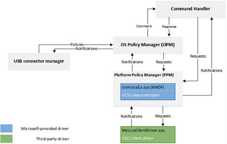
UCSI ACPI Interface
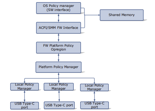
Shared Mailbox Interface
The following table is the reserved memory structure that must be reserved and shared with the EC for communication. When using FF-A this memory region must be statically carved out and 4K aligned and directly accessible by secure world.
| Offset (Bytes) | Mnemonic | Description | Direction | Size (bits) |
|---|---|---|---|---|
| 0 | VERSION | UCSI Version Number | PPM->OPM | 16 |
| 2 | RESERVED | Reserved | N/A | 16 |
| 4 | CCI | USB Type-C Command Status and Connector Change Indication | PPM->OPM | 32 |
| 8 | CONTROL | USB Type-C Control | OPM->PPM | 64 |
| 16 | MESSAGE IN | USB Type-C Message In | PPM->OPM | 128 |
| 32 | MESSAGE OUT | USB Type-C Message Out | OPM->PPM | 128 |
ACPI Definitions
Device(USBC) {
Name(_HID,EISAID(“USBC000”))
Name(_CID,EISAID(“PNP0CA0”))
Name(_UID,1)
Name(_DDN, “USB Type-C”)
Name(_ADR,0x0)
OperationRegion(USBC, SystemMemory, 0xFFFF0000, 0x30)
Field(USBC,AnyAcc,Lock,Preserve)
{
// USB C Mailbox Interface
VERS,16, // PPM-\>OPM Version
RES, 16, // Reservied
CCI, 32, // PPM-\>OPM CCI Indicator
CTRL,64, // OPM-\>PPM Control Messages
MSGI,128, // OPM-\>PPM Message In
MSGO,128, // PPM-\>OPM Message Out
}
Method(_DSM,4,Serialized,0,UnknownObj, {BuffObj, IntObj,IntObj,PkgObj})
{
// Compare passed in UUID to Supported UUID
If(LEqual(Arg0,ToUUID(“6f8398c2-7ca4-11e4-ad36-631042b5008f”)))
{
// Use FFA to send Notification event down to copy data to EC
If(LEqual(\\_SB.FFA0.AVAL,One)) {
CreateQwordField(BUFF,0,STAT) // Out – Status
CreateField(BUFF,128,128,UUID) // UUID of service
CreateByteField(BUFF,32, CMDD) // In – First byte of command
CreateField(BUFF,288,384,FIFD) // Out – Msg data
// Create USCI Doorbell Event
Store(0x0, CMDD) // UCSI set doorbell
Store(ToUUID("daffd814-6eba-4d8c-8a91-bc9bbf4aa301"), UUID) // UCSI
Store(USBC, FIFD) // Copy output data
Store(Store(BUFF, \_SB_.FFA0.FFAC), BUFF)
If(LEqual(STAT,0x0) ) // Check FF-A successful?
{
Return (FIFD)
}
} // End AVAL
Return(Zero)
} // End UUID
} // End DSM
}
EC Input Management
An EC may have several input devices including LID, Power key, touch and keyboard. HID based devices requiring low latency input, are recommended to be connected directly through a non-secure BUS interface such as I2C or I3C for performance reasons.
LID State
Monitor sensors that indicate lid state. If lid is opened, potentially boot the system. If lid is closed, potentially shut down or hibernate the system.
| ACPI | Description |
|---|---|
| _LID | Get state of LID device for clamshell designs |
ACPI Example for LID notificiation
Assuming that LID is managed by the EC during registration we register for Input Management service for a Virtual ID = 1
Name(_DSD, Package() {
ToUUID("daffd814-6eba-4d8c-8a91-bc9bbf4aa301"), //Device Prop UUID
Package() {
Package(2) {
"arm-arml0002-ffa-ntf-bind",
Package() {
1, // Revision
1, // Count of following packages
Package () {
ToUUID("e3168a99-4a57-4a2b-8c5e-11bcfec73406"), // Input Management UUID
Package () {
0x02, // Cookie for LID
}
},
}
}
}
}) // _DSD()
Method(_DSM, 0x4, NotSerialized)
{
// Arg0 - UUID
// Arg1 - Revision
// Arg2: Function Index
// 0 - Query
// 1 - Notify
// 2 - binding failure
// 3 - infra failure
// Arg3 - Data
//
// Device specific method used to query
// configuration data. See ACPI 5.0 specification
// for further details.
//
If(LEqual(Arg0, Buffer(0x10) {
//
// UUID: {7681541E-8827-4239-8D9D-36BE7FE12542}
//
0x1e, 0x54, 0x81, 0x76, 0x27, 0x88, 0x39, 0x42, 0x8d, 0x9d, 0x36, 0xbe, 0x7f, 0xe1, 0x25, 0x42
}))
{
// Query Function
If(LEqual(Arg2, Zero))
{
Return(Buffer(One) { 0x03 }) // Bitmask Query + Notify
}
// Notify Function
If(LEqual(Arg2, One))
{
// Arg3 - Package {UUID, Cookie}
Local0 = DeRefOf(Index(Arg3,1))
Switch(Local0) {
Case(2) {
Notify(\_SB._LID, 0x80)
}
}
}
}
Return(Buffer(One) { 0x00 })
}
System Wake Event
Ability to wake the system from various external events. This is for more complicated events that aren’t a simple GPIO for LID/Power button that require EC monitoring.
HID descriptor Interface
Communication with EC must have packet sent/received in HID format so the OS HIDClass driver can properly understand requests. At this time HID packets will go over HIDI2C but in future these HID packets could be included over a single interface.
| HID IOCTL | Description |
|---|---|
| IOCTL_HID_GET_DEVICE_DESCRIPTOR | Retrieves the device’s HID descriptor |
| IOCTL_HID_GET_DEVICE_ATTRIBUTES | Retrieves a device’s attributes in a HID_DEVICE_ATTRIBUTES structure |
| IOCTL_HID_GET_REPORT_DESCRIPTOR | Obtains the report descriptor for the HID device |
| IOCTL_HID_READ_REPORT | Returns a report from the device into a class driver-supplied buffer |
| IOCTL_HID_WRITE_REPORT | Transmits a class driver-supplied report to the device |
| IOCTL_HID_GET_FEATURE | Get capabilities of a feature from the device |
| IOCTL_HID_SET_FEATURE | Set/Enable a specific feature on device |
| IOCTL_HID_GET_INPUT_REPORT | Get input report from HID device if input device |
| IOCTL_HID_SET_OUTPUT_REPORT | Send output HID report to device |
| IOCTL_HID_GET_STRING | Get a specific string from device |
| IOCTL_HID_GET_INDEXED_STRING | Get a string from device based on index |
| IOCTL_HID_SEND_IDLE_NOTIFICATION | Notification to idle device into idle/sleep state |
EC Time Alarm Service
The following sections define the operation and definition of the optional control method-based Time and Alarm device, which provides a hardware independent abstraction and a more robust alternative to the Real Time Clock (RTC)
ACPI specification details are in version 6.5 Chapter 9.
| Command | Description |
|---|---|
| EC_TAS_GET_GCP = 0x1 | Get the capabilities of the time and alarm device |
| EC_TAS_GET_GRT = 0x2 | Get the Real Time |
| EC_TAS_SET_SRT = 0x3 | Set the Real Time |
| EC_TAS_GET_GWS = 0x4 | Get Wake Status |
| EC_TAS_SET_CWS = 0x5 | Clear Wake Status |
| EC_TAS_SET_STV = 0x6 | Set Timer value for given timer |
| EC_TAS_GET_TIV = 0x7 | Get Timer value remaining for given timer |
EC_TAS_GET_GCP
This object is required and provides the OSPM with a bit mask of the device capabilities.
9. ACPI-Defined Devices and Device-Specific Objects — ACPI Specification 6.5 documentation
Input Parameters
Input parameters as described in ACPI specification.
Output Parameters
Should return structure as defined by ACPI specification
FFA ACPI
Method (_GCP) {
// Check to make sure FFA is available and not unloaded
If(LEqual(\\_SB.FFA0.AVAL,One)) {
CreateQwordField(BUFF,0,STAT) // Out – Status for req/rsp
CreateField(BUFF,128,128,UUID) // UUID of service
CreateByteField(BUFF,32, CMDD) // In – First byte of command
CreateDwordField(BUFF,32,GCPD) // Out – 32-bit integer described above
Store(0x1, CMDD) // EC_TAS_GET_GCP
Store(ToUUID("23ea63ed-b593-46ea-b027-8924df88e92f"), UUID) // RTC
Store(Store(BUFF, \_SB_.FFA0.FFAC), BUFF)
If(LEqual(STAT,0x0) ) // Check FF-A successful?
{
Return (GCDD)
}
}
Return(Zero)
}
EC_TAS_GET_GRT
This object is required if the capabilities bit 2 is set to 1. The OSPM can use this object to get time. The return value is a buffer containing the time information as described below.
9. ACPI-Defined Devices and Device-Specific Objects — ACPI Specification 6.5 documentation
Input Parameters
Input parameters as described in ACPI specification.
Output Parameters
Should return structure as defined by ACPI specification
FFA ACPI Example
Method (_GRT) {
// Check to make sure FFA is available and not unloaded
If(LEqual(\\_SB.FFA0.AVAL,One)) {
CreateQwordField(BUFF,0,STAT) // Out – Status for req/rsp
CreateField(BUFF,128,128,UUID) // UUID of service
CreateByteField(BUFF,32, CMDD) // In – First byte of command
CreateWordField(BUFF,32,GRT0) // Out Year
CreateByteField(BUFF,36,GRT1) // Out Month
CreateByteField(BUFF,37,GRT2) // Out Day
CreateByteField(BUFF,38,GRT3) // Out Hour
CreateByteField(BUFF,39,GRT4) // Out Minute
CreateByteField(BUFF,40,GRT5) // Out Second
CreateByteField(BUFF,41,GRT6) // Out Valid
CreateWordField(BUFF,42,GRT7) // Out milliseconds
CreateWordField(BUFF,44,GRT8) // Out Timezone
CreateByteField(BUFF,46,GRT9) // Out Daylight
CreateField(BUFF,376,24,PAD0) // Out 3 bytes padding
Store(0x2, CMDD) // EC_TAS_GET_GRT
Store(ToUUID("23ea63ed-b593-46ea-b027-8924df88e92f"), UUID) // RTC
Store(Store(BUFF, \_SB_.FFA0.FFAC), BUFF)
If(LEqual(STAT,0x0) ) // Check FF-A successful?
{
Return (Package() {GRT0,GRT1,GRT2,GRT3,GRT4,GRT5,GRT6,GRT7,GRT8,GRT9, PAD0})
}
}
Return(Package() {0,0,0,0,0,0,0,0,0,0,Buffer(){0,0,0}})
}
EC_TAS_SET_SRT
This object is required if the capabilities bit 2 is set to 1. The OSPM can use this object to set the time.
9. ACPI-Defined Devices and Device-Specific Objects — ACPI Specification 6.5 documentation
Input Parameters
Input parameters as described in ACPI specification.
Output Parameters
Should return structure as defined by ACPI specification
FFA ACPI Example
Method (_SRT) {
// Check to make sure FFA is available and not unloaded
If(LEqual(\\_SB.FFA0.AVAL,One)) {
CreateQwordField(BUFF,0,STAT) // Out – Status for req/rsp
CreateField(BUFF,128,128,UUID) // UUID of service
CreateByteField(BUFF,32, CMDD) // In – First byte of command
CreateField(BUFF,264,128,SRTD) // 16 bytes of data
Store(0x3, CMDD) // EC_TAS_SET_SRT
Store(ToUUID("23ea63ed-b593-46ea-b027-8924df88e92f"), UUID) // RTC
Store(Arg0, SRTD) // Copy over the RTC data
Store(Store(BUFF, \_SB_.FFA0.FFAC), BUFF)
If(LEqual(STAT,0x0) ) // Check FF-A successful?
{
Return (One)
}
}
Return(Zero)}
}
EC_TAS_GET_GWS
This object is required if the capabilities bit 0 is set to 1. It enables the OSPM to read the status of wake alarms
9. ACPI-Defined Devices and Device-Specific Objects — ACPI Specification 6.5 documentation
Input Parameters
Input parameters as described in ACPI specification.
Output Parameters
Should return structure as defined by ACPI specification
FFA ACPI Example
Method (_GWS) {
// Check to make sure FFA is available and not unloaded
If(LEqual(\\_SB.FFA0.AVAL,One)) {
CreateQwordField(BUFF,0,STAT) // Out – Status for req/rsp
CreateField(BUFF,128,128,UUID) // UUID of service
CreateByteField(BUFF,32, CMDD) // In – First byte of command
CreateDwordField(BUFF,33,GWS1) // In – Dword for timer type AC/DC
CreateDwordField(BUFF,32,GWSD) // Out – Dword timer state
Store(20, LENG)
Store(0x4, CMDD) // EC_TAS_GET_GWS
Store(Arg0, GWS1)
Store(ToUUID("23ea63ed-b593-46ea-b027-8924df88e92f"), UUID) // RTC
Store(Store(BUFF, \_SB_.FFA0.FFAC), BUFF)
If(LEqual(STAT,0x0) ) // Check FF-A successful?
{
Return (GWSD)
}
}
Return(Zero)
}
EC_TAS_SET_CWS
This object is required if the capabilities bit 0 is set to 1. It enables the OSPM to clear the status of wake alarms
9. ACPI-Defined Devices and Device-Specific Objects — ACPI Specification 6.5 documentation
Input Parameters
Input parameters as described in ACPI specification.
Output Parameters
Should return structure as defined by ACPI specification
FFA ACPI Example
Method (_CWS) {
// Check to make sure FFA is available and not unloaded
If(LEqual(\\_SB.FFA0.AVAL,One)) {
CreateQwordField(BUFF,0,STAT) // Out – Status for req/rsp
CreateField(BUFF,128,128,UUID) // UUID of service
CreateByteField(BUFF,32, CMDD) // In – First byte of command
CreateDwordField(BUFF,33, CWS1) // In – Dword for timer type AC/DC
CreateDwordField(BUFF,32,CWSD) // Out – Dword timer state
Store(20, LENG)
Store(0x5, CMDD) // EC_TAS_SET_CWS
Store(Arg0,CWS1)
Store(ToUUID("23ea63ed-b593-46ea-b027-8924df88e92f"), UUID) // RTC
Store(Store(BUFF, \_SB_.FFA0.FFAC), BUFF)
If(LEqual(STAT,0x0) ) // Check FF-A successful?
{
Return (CWSD)
}
}
Return(Zero)
}
EC_TAS_SET_STV
This object is required if the capabilities bit 0 is set to 1. It sets the timer to the specified value.
9. ACPI-Defined Devices and Device-Specific Objects — ACPI Specification 6.5 documentation
Input Parameters
Input parameters as described in ACPI specification.
Output Parameters
Should return structure as defined by ACPI specification
FFA ACPI Example
Method (_STV) {
// Check to make sure FFA is available and not unloaded
If(LEqual(\\_SB.FFA0.AVAL,One)) {
CreateQwordField(BUFF,0,STAT) // Out – Status for req/rsp
CreateField(BUFF,128,128,UUID) // UUID of service
CreateByteField(BUFF,32, CMDD) // In – First byte of command
CreateDwordField(BUFF,33, STV1) // In – Dword for timer type AC/DC
CreateDwordField(BUFF,37, STV2) // In – Dword Timer Value
CreateDwordField(BUFF,2,STVD) // Out – Dword timer state
Store(0x6, CMDD) // EC_TAS_SET_STV
Store(Arg0,STV1)
Store(Arg1,STV2)
Store(ToUUID("23ea63ed-b593-46ea-b027-8924df88e92f"), UUID) // RTC
Store(Store(BUFF, \_SB_.FFA0.FFAC), BUFF)
If(LEqual(STAT,0x0) ) // Check FF-A successful?
{
Return (STVD)
}
}
Return(Zero)
}
EC_TAS_GET_TIV
This object is required if the capabilities bit 0 is set to 1. It returns the remaining time of the specified timer before that expires.
9. ACPI-Defined Devices and Device-Specific Objects — ACPI Specification 6.5 documentation
Input Parameters
Input parameters as described in ACPI specification.
Output Parameters
Should return structure as defined by ACPI specification
FFA ACPI Example
Method (_TIV) {
// Check to make sure FFA is available and not unloaded
If(LEqual(\\_SB.FFA0.AVAL,One)) {
CreateQwordField(BUFF,0,STAT) // Out – Status for req/rsp
CreateField(BUFF,128,128,UUID) // UUID of service
CreateByteField(BUFF,32, CMDD) // In – First byte of command
CreateDwordField(BUFF,33, TIV1) // In – Dword for timer type AC/DC
CreateDwordField(BUFF,32,TIVD) // Out – Dword timer state
Store(0x7, CMDD) // EC_TAS_GET_TIV
Store(Arg0,TIV1)
Store(ToUUID("23ea63ed-b593-46ea-b027-8924df88e92f"), UUID) // RTC
Store(Store(BUFF, \_SB_.FFA0.FFAC), BUFF)
If(LEqual(STAT,0x0) ) // Check FF-A successful?
{
Return (TIVD)
}
}
Return(Zero)
}
EC Debug Service
The debug service is used for telemetry, debug logs, system reset information etc.
Recovery Mode
Put EC into recovery mode for development flashing and debugging.
Dump Debug State
EC should be able to support typical engineering requests, such as getting detailed subsystem information, setting/getting GPIOs, etc, for design verification and benchtop testing.
Telemetry
Ability to communicate with the HLOS event logging system, and record EC critical events for later analysis.
System Boot State
In many designs, OEMs will desire indication that the system is responding to a power on request. This could be a logo display on the screen or a bezel LED. EC should be able to control these devices during the boot sequence.
During first boot sequence EC may also be initialized and setup its services. Needs to know when OS is up to send notification for events that are only used by OS.
Memory Mapped Transactions
There are two cases where you may want to use the memory mapped transactions. The first is if you have a large buffer you need to transfer data between EC and HLOS like a debug buffer. The second use case is if you want to emulate an eSPI memory mapped interface for compatibility with legacy devices.
For this mode to work you will need memory carved out which is dedicated and shared between HLOS and secure world. In your UEFI memory map this memory should be marked as EfiMemoryReservedType so that the OS will not use or allocate the memory. In your SP manifest file you will also need to add access to this physical memory range. It needs to be aligned on a 4K boundary and a multiple of 4K. This memory region is carved out and must never be used for any other purpose. Since the memory is shared with HLOS there is also no security surrounding accesses to the memory.
Example Memory Mapped Interface
// Map 4K memory region shared
OperationRegion(ABCD, SystemMemory, 0xFFFF0000, 0x1000)
// DSM Method to send sync event
Method(_DSM,4,Serialized,0,UnknownObj, {BuffObj, IntObj,IntObj,PkgObj})
{
// Compare passed in UUID to Supported UUID
If(LEqual(Arg0,ToUUID(“6f8398c2-7ca4-11e4-ad36-631042b5008f”)))
{
// Use FFA to send Notification event down to copy data to EC
If(LEqual(\\_SB.FFA0.AVAL,One)) {
CreateQwordField(BUFF,0,STAT) // Out – Status for req/rsp
CreateField(BUFF,128,128,UUID) // UUID of service
CreateByteField(BUFF,32, CMDD) // In – First byte of command
// Create Doorbell Event to read shared memory
Store(0x0, CMDD) //
Store(ToUUID("daffd814-6eba-4d8c-8a91-bc9bbf4aa301"), UUID) // Debug Service UUID
Store(Store(BUFF, \_SB_.FFA0.FFAC), BUFF)
} // End AVAL
} // End UUID
} // End DSM
Any updates from the EC come back through a notification event registered in the FFA for this particular service.
EC Manufacturing Service
This service should contain all the functionality that is need to perform self test, validation of the EC and special manufacturing modes. This service should be disabled on retail devices or at least protected to prevent unwanted modes.
Self Test
EC should perform self test and return results/details of test validation
Set Calibration Data
Have ability to store factory calibrations and setup information into EC non-volatile memory. For instance keyboard language information, or thermistor calibration values.
EC OEM Service
Any OEM special custom features should be put in their own service sandbox to support OEM specific features. This will prevent definitions from colliding with other services.
Sample System Implementation
ACPI Interface Definition
FFA Device Definition
Device(\_SB_.FFA0) {
Name(_HID, "MSFT000C")
OperationRegion(AFFH, FFixedHw, 4, 144)
Field(AFFH, BufferAcc, NoLock, Preserve) { AccessAs(BufferAcc, 0x1), FFAC, 1152 }
// Other components check this to make sure FFA is available
Method(AVAL, 0, Serialized) {
Return(One)
}
// Register notification events from FFA
Method(_RNY, 0, Serialized) {
Return( Package() {
Package(0x2) { // Events for Management Service
ToUUID("330c1273-fde5-4757-9819-5b6539037502"),
Buffer() {0x1,0x0} // Register event 0x1
},
Package(0x2) { // Events for Thermal service
ToUUID("31f56da7-593c-4d72-a4b3-8fc7171ac073"),
Buffer() {0x1,0x0,0x2,0x0,0x3,0x0} // Register events 0x1, 0x2, 0x3
},
Package(0x2) { // Events for input device
ToUUID("e3168a99-4a57-4a2b-8c5e-11bcfec73406"),
Buffer() {0x1,0x0} // Register event 0x1 for LID
}
} )
}
Method(_NFY, 2, Serialized) {
// Arg0 == UUID
// Arg1 == Notify ID
// Management Service Events
If(LEqual(ToUUID("330c1273-fde5-4757-9819-5b6539037502"),Arg0)) {
Switch(Arg1) {
Case(1) { // Test Notification Event
Notify(\_SB.ECT0,0x20)
}
}
}
// Thermal service events
If(LEqual(ToUUID("31f56da7-593c-4d72-a4b3-8fc7171ac073"),Arg0)) {
Switch(Arg1) {
Case(1) { // Temp crossed low threshold
Notify(\_SB.SKIN,0x80)
}
Case(2) { // Temp crossed high threshold
Notify(\_SB.SKIN,0x81)
}
Case(3) { // Critical temperature event
Notify(\_SB.SKIN,0x82)
}
}
}
// Input Device Events
If(LEqual(ToUUID("e3168a99-4a57-4a2b-8c5e-11bcfec73406"),Arg0)) {
Switch(Arg1) {
Case(1) { // LID event
Notify(\_SB._LID,0x80)
}
}
}
}
}
Memory Mapped Interface via FFA for UCSI
Note for this implementation of memory mapped interface to work the memory must be marked as reserved by UEFI and not used by the OS and direct access also given to the corresponding service in secure world.
Device(USBC) {
Name(_HID,EISAID(“USBC000”))
Name(_CID,EISAID(“PNP0CA0”))
Name(_UID,1)
Name(_DDN, “USB Type-C”)
Name(_ADR,0x0)
Name(BUFF, Buffer(144){}) // Create buffer for FFA data
OperationRegion(USBC, SystemMemory, UCSI_PHYS_MEM, 0x30)
Field(USBC,AnyAcc,Lock,Preserve)
{
// USB C Mailbox Interface
VERS,16, // PPM-\>OPM Version
RES, 16, // Reservied
CCI, 32, // PPM-\>OPM CCI Indicator
CTRL,64, // OPM-\>PPM Control Messages
MSGI,128, // OPM-\>PPM Message In
MSGO,128, // PPM-\>OPM Message Out
}
Method(_DSM,4,Serialized,0,UnknownObj, {BuffObj, IntObj,IntObj,PkgObj})
{
// Compare passed in UUID to Supported UUID
If(LEqual(Arg0,ToUUID(“6f8398c2-7ca4-11e4-ad36-631042b5008f”)))
{
// Use FFA to send Notification event down to copy data to EC
If(LEqual(\_SB.FFA0.AVAL,One)) {
CreateQwordField(BUFF,0,STAT) // Out – Status for req/rsp
CreateField(BUFF,128,128,UUID) // UUID of service
CreateByteField(BUFF,32, CMDD) // In – First byte of command
CreateField(BUFF,288,384,FIFD) // Out – Msg data
// Create Doorbell Event
Store(0x0, CMDD) // UCSI set doorbell
Store(ToUUID("daffd814-6eba-4d8c-8a91-bc9bbf4aa301"), UUID)
Store(USBC,FIFD)
Store(Store(BUFF, \_SB_.FFA0.FFAC), BUFF)
} // End AVAL
} // End UUID
} // End DSM
}
Thermal ACPI Interface for FFA
This sample code shows one Microsoft Thermal zone for SKIN and then a thermal device THRM for implementing customized IO.
// Sample Definition of FAN ACPI
Device(SKIN) {
Name(_HID, "MSFT000A")
Method(_TMP, 0x0, Serialized) {
If(LEqual(\_SB.FFA0.AVAL,One)) {
CreateQwordField(BUFF,0,STAT) // Out – Status for req/rsp
CreateField(BUFF,128,128,UUID) // UUID of service
CreateByteField(BUFF,32,CMDD) // Command register
CreateByteField(BUFF,33,TZID) // Temp Sensor ID
CreateDWordField(BUFF,32,RTMP) // Output Data
Store(0x1, CMDD) // EC_THM_GET_TMP
Store(0x2, TZID) // Temp zone ID for SKIIN
Store(ToUUID("31f56da7-593c-4d72-a4b3-8fc7171ac073"), UUID)
Store(Store(BUFF, \_SB_.FFA0.FFAC), BUFF)
If(LEqual(STAT,0x0) ) // Check FF-A successful?
{
Return (RTMP)
}
}
Return (Ones)
}
// Arg0 Temp sensor ID
// Arg1 Package with Low and High set points
Method(THRS,0x2, Serialized) {
If(LEqual(\_SB.FFA0.AVAL,One)) {
CreateQwordField(BUFF,0,STAT) // Out – Status for req/rsp
CreateField(BUFF,128,128,UUID) // UUID of service
CreateByteField(BUFF,32,CMDD) // Command register
CreateByteField(BUFF,33,TZID) // Temp Sensor ID
CreateDwordField(BUFF,34,VTIM) // Timeout
CreateDwordField(BUFF,38,VLO) // Low Threshold
CreateDwordField(BUFF,42,VHI) // High Threshold
CreateDWordField(BUFF,46,TSTS) // Output Data
Store(ToUUID("31f56da7-593c-4d72-a4b3-8fc7171ac073"), UUID)
Store(0x2, CMDD) // EC_THM_SET_THRS
Store(Arg0, TZID)
Store(DeRefOf(Index(Arg1,0)),VTIM)
Store(DeRefOf(Index(Arg1,1)),VLO)
Store(DeRefOf(Index(Arg1,2)),VHI)
Store(Store(BUFF, \_SB_.FFA0.FFAC), BUFF)
If(LEqual(STAT,0x0) ) // Check FF-A successful?
{
Return (TSTS)
}
}
Return (0x3) // Hardware failure
}
// Arg0 GUID 1f0849fc-a845-4fcf-865c-4101bf8e8d79
// Arg1 Revision
// Arg2 Function Index
// Arg3 Function dependent
Method(_DSM, 0x4, Serialized) {
If(LEqual(ToUuid("1f0849fc-a845-4fcf-865c-4101bf8e8d79"),Arg0)) {
Switch(Arg2) {
Case (0) {
Return(0x3) // Support Function 0 and Function 1
}
Case (1) {
Return( THRS(0x2, Arg3) ) // Call to function to set threshold
}
}
}
Return(0x3)
}
}
Device(THRM) {
Name(_HID, "MSFT000B")
// Arg0 Instance ID
// Arg1 UUID of variable
// Return (Status,Value)
Method(GVAR,2,Serialized) {
If(LEqual(\_SB.FFA0.AVAL,One)) {
CreateQwordField(BUFF,0,STAT) // Out – Status for req/rsp
CreateField(BUFF,128,128,UUID) // UUID of service
CreateByteField(BUFF,32,CMDD) // Command register
CreateByteField(BUFF,33,INST) // Instance ID
CreateWordField(BUFF,34,VLEN) // 16-bit variable length
CreateField(BUFF,288,128,VUID) // UUID of variable to read
CreateQwordField(BUFF,52,64,RVAL) // Output Data
Store(ToUUID("31f56da7-593c-4d72-a4b3-8fc7171ac073"), UUID)
Store(0x5, CMDD) // EC_THM_GET_VAR
Store(Arg0,INST) // Save instance ID
Store(4,VLEN) // Variable is always DWORD here
Store(Arg1, VUID)
Store(Store(BUFF, \_SB_.FFA0.FFAC), BUFF)
If(LEqual(STAT,0x0) ) // Check FF-A successful?
{
Return (RVAL)
}
}
Return (0x3)
}
// Arg0 Instance ID
// Arg1 UUID of variable
// Return (Status,Value)
Method(SVAR,3,Serialized) {
If(LEqual(\_SB.FFA0.AVAL,One)) {
CreateQwordField(BUFF,0,STAT) // Out – Status for req/rsp
CreateField(BUFF,128,128,UUID) // UUID of service
CreateByteField(BUFF,32,CMDD) // Command register
CreateByteField(BUFF,33,INST) // Instance ID
CreateWordField(BUFF,34,VLEN) // 16-bit variable length
CreateField(BUFF,288,128,VUID) // UUID of variable to Write
CreateQwordField(BUFF,52,64,RVAL) // Output Data
CreateDwordField(BUFF,60,DVAL) // Data value
Store(ToUUID("31f56da7-593c-4d72-a4b3-8fc7171ac073"), UUID)
Store(0x6, CMDD) // EC_THM_SET_VAR
Store(Arg0,INST) // Save instance ID
Store(4,VLEN) // Variable is always DWORD here
Store(Arg1, VUID)
Store(Arg2,DVAL)
Store(Store(BUFF, \_SB_.FFA0.FFAC), BUFF)
If(LEqual(STAT,0x0) ) // Check FF-A successful?
{
Return (RVAL)
}
}
Return (0x3)
}
// Arg0 GUID
// 07ff6382-e29a-47c9-ac87-e79dad71dd82 - Input
// d9b9b7f3-2a3e-4064-8841-cb13d317669e - Output
// Arg1 Revision
// Arg2 Function Index
// Arg3 Function dependent
Method(_DSM, 0x4, Serialized) {
// Input Variable
If(LEqual(ToUuid("07ff6382-e29a-47c9-ac87-e79dad71dd82"),Arg0)) {
Switch(Arg2) {
Case(0) {
// We support function 0-3
Return(0xf)
}
Case(1) {
Return(GVAR(1,ToUuid("ba17b567-c368-48d5-bc6f-a312a41583c1"))) // OnTemp
}
Case(2) {
Return(GVAR(1,ToUuid("3a62688c-d95b-4d2d-bacc-90d7a5816bcd"))) // RampTemp
}
Case(3) {
Return(GVAR(1,ToUuid("dcb758b1-f0fd-4ec7-b2c0-ef1e2a547b76"))) // MaxTemp
}
}
Return(0x1)
}
// Output Variable
If(LEqual(ToUuid("d9b9b7f3-2a3e-4064-8841-cb13d317669e"),Arg0)) {
Switch(Arg2) {
Case(0) {
// We support function 0-3
Return(0xf)
}
Case(1) {
Return(SVAR(1,ToUuid("ba17b567-c368-48d5-bc6f-a312a41583c1"),Arg3)) // OnTemp
}
Case(2) {
Return(SVAR(1,ToUuid("3a62688c-d95b-4d2d-bacc-90d7a5816bcd"),Arg3)) // RampTemp
}
Case(3) {
Return(SVAR(1,ToUuid("dcb758b1-f0fd-4ec7-b2c0-ef1e2a547b76"),Arg3)) // MaxTemp
}
}
}
Return (0x1)
}
}
Call Flows for secure and non-secure Implementation
Depending on system requirements the ACPI calls may go directly to the EC or through secure world then through to EC.
When using non-secure interface the ACPI functions must define protocol level which is the Embedded controller for eSPI. For I2C/I3C or SPI interfaces the corresponding ACPI device must define the bus dependency and build the packet directly that is sent to the EC.
For secure communication all data is sent to the secure world via FF-A commands described in this document and the actual bus protocol and data sent to the EC is defined in the secure world in Hafnium. All support for FF-A is inboxed in the OS by default so EC communication will always work in any environment. However, FF-A is not supported in x86/x64 platforms so direct EC communication must be used on these platforms.
Non-Secure eSPI Access
This call flow assumes using Embedded controller definition with independent ACPI functions for MPTF support
Non-Secure eSPI READ
Device(EC0) {
Name(_HID, EISAID("PNP0C09")) // ID for this EC
// current resource description for this EC
Name(_CRS, ResourceTemplate() {
Memory32Fixed (ReadWrite, 0x100000, 0x10) // Used for simulated port access
Memory32Fixed (ReadWrite, 0x100010, 0x10)
// Interrupt defined for eSPI event signalling
GpioInt(Edge, ActiveHigh, ExclusiveAndWake,PullUp 0,"\_SB.GPI2"){43}
})
Name(_GPE, 0) // GPE index for this EC
// create EC's region and field for thermal support
OperationRegion(EC0, EmbeddedControl, 0, 0xFF)
Field(EC0, ByteAcc, Lock, Preserve) {
MODE, 1, // thermal policy (quiet/perform)
FAN, 1, // fan power (on/off)
, 6, // reserved
TMP, 16, // current temp
AC0, 16, // active cooling temp (fan high)
, 16, // reserved
PSV, 16, // passive cooling temp
HOT 16, // critical S4 temp
CRT, 16 // critical temp
BST1, 32, // Battery State
BST2, 32, // Battery Present Rate
BST3, 32, // Battery Remaining capacity
BST4, 32, // Battery Present Voltage
}
Method (_BST) {
Name (BSTD, Package (0x4)
{
\_SB.PCI0.ISA0.EC0.BST1, // Battery State
\_SB.PCI0.ISA0.EC0.BST2, // Battery Present Rate
\_SB.PCI0.ISA0.EC0.BST3, // Battery Remaining Capacity
\_SB.PCI0.ISA0.EC0.BST4, // Battery Present Voltage
})
Return(BSTD)
}
}
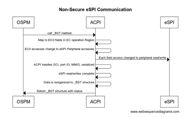
Non-Secure eSPI Notifications
All interrupts are handled by the ACPI driver. When EC needs to send a notification event the GPIO is asserted and traps into IRQ. ACPI driver reads the EC_SC status register to determine if an SCI is pending. DPC callback calls and reads the EC_DATA port to determine the _Qxx event that is pending. Based on the event that is determined by ACPI the corresponding _Qxx event function is called.
Method (_Q07) {
// Take action for event 7
Notify(\_SB._LID, 0x80)
}
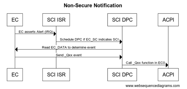
Secure eSPI Access
The following flow assumes ARM platform using FF-A for secure calls. Note if you want to use the same EC firmware on both platforms with secure and non-secure access the EC_BAT_GET_BST in this case should be convert to a peripheral access with the same IO port and offset as non-secure definition.
Secure eSPI READ
Method (_BST, 0, Serialized) {
// Check to make sure FFA is available and not unloaded
If(LEqual(\_SB.FFA0.AVAL,One)) {
CreateDwordField(BUFF,0,STAT) // Out – Status for req/rsp
CreateField(BUFF,128,128,UUID) // UUID of service
CreateByteField(BUFF,32,CMDD) // In – First byte of command
CreateDwordField(BUFF,32,BST0) // Out – Battery State DWord
CreateDwordField(BUFF,36,BST1) // Out – Battery Rate DWord
CreateDwordField(BUFF,40,BST2) // Out – Battery Reamining Capacity DWord
CreateDwordField(BUFF,44,BST3) // Out – Battery Voltage DWord
Store(0x2, CMDD) //EC_BAT_GET_BST
Store(ToUUID("25cb5207-ac36-427d-aaef-3aa78877d27e"), UUID)
Store(Store(BUFF, \_SB_.FFA0.FFAC), BUFF)
If(LEqual(STAT,0x0) ) // Check FF-A successful?
{
return(Package() {BST0, BST1, BST2, BST3} )
}
}
Return(Package() {0,0,0,0})
}
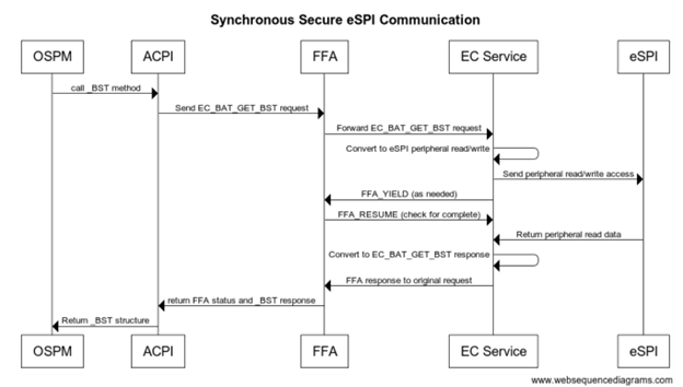
Secure eSPI Notification
When EC communication is done through Secure world we assert FIQ which is handled as eSPI interrupt. eSPI driver reads EC_SC and EC_DATA to retrieve the notification event details. On Non-secure implementation ACPI converts this to Qxx callback. On secure platform this is converted to a virtual ID and sent back to the OS via _NFY callback and a virtual ID.
Method(_DSM, 0x4, NotSerialized)
{
// Arg0 - UUID
// Arg1 - Revision
// Arg2: Function Index
// 0 - Query
// 1 - Notify
// 2 - binding failure
// 3 - infra failure
// Arg3 - Data
//
// Device specific method used to query
// configuration data. See ACPI 5.0 specification
// for further details.
//
If(LEqual(Arg0, Buffer(0x10) {
//
// UUID: {7681541E-8827-4239-8D9D-36BE7FE12542}
//
0x1e, 0x54, 0x81, 0x76, 0x27, 0x88, 0x39, 0x42, 0x8d, 0x9d, 0x36, 0xbe, 0x7f, 0xe1, 0x25, 0x42
}))
{
// Query Function
If(LEqual(Arg2, Zero))
{
Return(Buffer(One) { 0x03 }) // Bitmask Query + Notify
}
// Notify Function
If(LEqual(Arg2, One))
{
// Arg3 - Package {UUID, Cookie}
Store(DeRefOf(Index(Arg3,1)), \_SB.ECT0.NEVT )
If(LEqual(0x2,\_SB.ECT0.NEVT)) {
Notify(\_SB._LID, 0x80)
}
}
}
Return(Buffer(One) { 0x00 })
}